TMC2660 problem
-
@jerolee Your readings are correct. I have the same stepper and it works fine. Do you know that they are wired differently than the typical Nema 17 motor? What do you have the current set to?
-
@jerolee said in TMC2660 problem:
I got 2 brandnew and 1 older, all measure about the same. odd it is.
OK, that same place I linked to also sells the exact motor you have; 2.1 Ohms, 1.2mH inductance.
https://www.printedsolid.com/products/ldo-nema14-36mm-round-pancake-motor-ldo-36sth20-1004ahAround 2 ohms is common for steppers, that should not cause a problem.
Check continuity at the Duet plug? The winding should be 1-2 and 3-4, whichever end you start from.
(Some extension / adapter cables have two wires swapped).
-
@rjenkinsgb
thats what makes it so frustrating. i got the pairs/coils in the connector like 1-1-2-2. just as the NEMA17 coils are in their connector.
If i pair them up wrong, they make a not so nice sound") so the wiring is not the problem.
so the wiring is not the problem.
NEMA17 works fine on same driver , pancake just wont rotate.
I have tested other drivers, same result.Im gettin a bit tired of reprap and duet to be honest, i never had any problems with marlin boards. with these, there seems always something.
Switches not detected, Gantry tramming doesnt work consistantly etc.... -
@jerolee I used to have a Duet2 (Ethernet rather than WiFi) with Duex 5 expansion board (same drivers as far as I know) and I used to drive 5 pancake steppers without any problems (although I don't remember the spec). Maybe there is something about the way you have the board configured but unless you post your configuration files it's hard to say.
-
@jerolee Are you absolutely sure about the motor wiring? I have a similar motor (17mm) in my V0.1
My connector is red, green , yellow, blue as described below. Yours doesn't seem to be connected the same way. I assume you have checked this as you've measured the resistance.
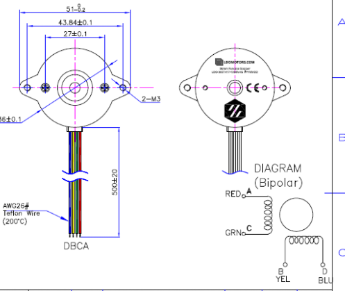
https://cdn.shopify.com/s/files/1/0239/9287/files/HT_LDO-36STH20-1004AHG_XH_RevA.pdf
-
@gixxerfast
hi mate,I just tested my 3 pancakes on my ender 3 which has a SKR board and runs marlin. pancakes run fine. no problems.
Im gonna sell my duet2 wifi duex tft, never gonna look back.
I just ordered a BTT Octopus board which has 8 drivers on it with TMC 2209's all problems sorted. -
 undefined jerolee has marked this topic as solved
-
@jerolee ..... Thats than Bad for you ,;) its definitly Not the duet
-
@jerolee you have wired the motor to the plug incorrectly. The diagram posted by @Gixxerfast shows that red and green are one phase, therefore they need to be adjacent and at one end of the connector. That's not what I see in your photo. You will get the same problem if you use your existing wiring order with any other control board.
Duet WiFi hardware designer and firmware engineer
Please do not ask me for Duet support via PM or email, use the forum
http://www.escher3d.com, https://miscsolutions.wordpress.com -
@dc42
the diagram showed does not represent de motor i have. i measured the coils and the correct pairs for my motor are black/green and red/blue.
Otherwise i couldnt measure the resistance no?So, this is not a wiring problem, i got more pancakes with different color wires. i measure the coils which are what and then connect, same problem no rotation, just a little bit of hum. when i connect a nema17 thats runs quite normal, i noticed however some hickup that it wouldnt start rotating.
I also tested the round 36mm pancakes on other drivers on the board X, Y, Z (these drive my NEMA17's. all drivers same result, no rotation.
It must be some PWM or whatever signal not quite work with the small round motors?Further... i used same pancake motors with connector on my ender 3 board, motors run normally.
I just have no clue whats goin on here. i post my config file.; Drives
M569 P0 S0 ; physical drive 0 goes backwards
M569 P1 S1 ; physical drive 1 goes forwards
M569 P2 S0 ; physical drive 2 goes backwards
M569 P3 S0 ; physical drive 3 goes backwards
M569 P4 S0 ; physical drive 4 goes backwards
M569 P5 S0 ; physical drive 5 goes backwards
M569 P6 S0 ; physical drive 6 goes backwards
M569 P7 S0 ; physical drive 7 goes backwardsM584 X0 Y1:4 Z2:5:6:7 E3 ; set drive mapping
M671 X-60:-60:660:660 Y-48:378:378:-48 S7 ; set the coordinates of the 4 Z-axis drivers
M350 X16 Y16 Z16 E16 I1 ; configure microstepping with interpolation
M92 X80.03 Y79.84:79.84 Z1615.90:1621.26:1621.69:1619.23 E300.00 ; set steps per mm
M566 X900.00 Y900.00:900.00 Z60.00:60.00:60.00:60.00 E500.00 ; set maximum instantaneous speed changes (mm/min)
M203 X10000.00 Y10000.00:10000.00 Z500.00:500.00:500.00:500.00 E1000.00 ; set maximum speeds (mm/min)
M201 X500.00 Y500.00:500.00 Z20.00:20.00:20.00:20.00 E500.00 ; set accelerations (mm/s^2)
M906 X800 Y800:800 Z800:800:800:800 E800 I30 ; set motor currents (mA) and motor idle factor in per cent
M84 S30 ; Set idle timeout; Axis Limits
M208 X0 Y0 Z0 S1 ; set axis minima
M208 X600 Y300 Z470 S0 ; set axis maxima; Endstops
M574 X1 S1 P"!xstop" ; configure active-low endstop for low end on X via pin !xstop
M574 Y1 S1 P"!ystop+!e1stop" ; configure active-low endstop for low end on Y via pin !ystop
M574 Z1 S2 ; configure Z-probe endstop for low end on Z; Z-Probe
M950 S0 C"duex.pwm1" ; create servo pin 0 for BLTouch
M558 P9 C"^zprobe.in" H5 F120 T4000 ; set Z probe type to bltouch and the dive height + speeds
G31 P500 X36 Y9 Z0 ; set Z probe trigger value, offset and trigger height
M557 X65:585 Y20:280 S130 ; define mesh grid;Filament Runout switch
M591 D0 P2 C"e0stop" S1 ; filament switch; Heaters
M308 S0 P"bedtemp" Y"thermistor" T100000 B3950 R4700 ; configure sensor 0 as thermistor on pin bedtemp
M950 H0 C"bedheat" T0 ; create bed heater output on bedheat and map it to sensor 0
M307 H0 B0 S1.00 ; disable bang-bang mode for the bed heater and set PWM limit
M140 H0 ; map heated bed to heater 0
M143 H0 S120 ; set temperature limit for heater 0 to 120C
M308 S1 P"e0temp" Y"pt1000" T100000 B4000 R4700 ; configure sensor 1 as thermistor on pin e0temp
M950 H1 C"e0heat" T1 ; create nozzle heater output on e0heat and map it to sensor 1
M307 H1 B0 R2.926 C244.4 D10.45 S1.00 V25.0 ; disable bang-bang mode for heater and set PWM limit
M143 H1 S260 ; set temperature limit for heater 1 to 260C; Fans
M950 F0 C"fan0" Q500 ; create fan 0 "part fan" on pin fan0 and set its frequency
M106 P0 S0 H-1 ; set fan 0 value. Thermostatic control is turned off
M950 F1 C"fan1" Q500 ; create fan 1 "hotend fan"on pin fan1 and set its frequency
M106 P1 S1 H1 T70 ; set fan 1 value. Thermostatic control is turned on; Tools
M563 P0 D0 H1 F0 ; define tool 0
G10 P0 X0 Y0 Z0 ; set tool 0 axis offsets
G10 P0 R0 S0 ; set initial tool 0 active and standby temperatures to 0C; Custom settings are not defined
-
undefined jerolee has marked this topic as unsolved
-
there are some erros in cour config. please give me a sec.
-
M569 P0 S0 ; physical drive 0 goes backwards
M569 P1 S1 ; physical drive 1 goes forwards
M569 P2 S0 ; physical drive 2 goes backwards
M569 P3 S0 ; physical drive 3 goes backwards
M569 P4 S0 ; physical drive 4 goes backwards
M569 P5 S0 ; physical drive 5 goes backwards
M569 P6 S0 ; physical drive 6 goes backwards
M569 P7 S0 ; physical drive 7 goes backwards

M584 X0 Y1:4 Z2:5:6:7 E3 ; set drive mapping
M671 X-60:-60:660:660 Y-48:378:378:-48 S7 ; set the coordinates of the 4 Z-axis drivers
M350 X16 Y16 Z16 E16 I1 ; configure microstepping with interpolation
M92 X80.03 Y79.84 Z1615.90 E300.00 ; set steps per mm
M566 X900.00 Y900.00 Z60.00 E500.00 ; set maximum instantaneous speed changes (mm/min)
M203 X10000.00 Y10000.00 Z500.00 E1000.00 ; set maximum speeds (mm/min)
M201 X500.00 Y500.00 Z20.00 E500.00 ; set accelerations (mm/s^2)
M906 X800 Y800 Z800 E800 I30 ; set motor currents (mA) and motor idle factor in per cent
M84 S30 ; Set idle timeout

; Axis Limits
M208 X0 Y0 Z0 S1 ; set axis minima
M208 X600 Y300 Z470 S0 ; set axis maxima

; Endstops
M574 X1 S1 P"!xstop" ; configure active-low endstop for low end on X via pin !xstop
M574 Y1 S1 P"!ystop+!e1stop" ; configure active-low endstop for low end on Y via pin !ystop
M574 Z1 S2 ; configure Z-probe endstop for low end on Z

; Z-Probe
M950 S0 C"duex.pwm1" ; create servo pin 0 for BLTouch
M558 P9 C"^zprobe.in" H5 F120 T4000 ; set Z probe type to bltouch and the dive height + speeds
G31 P500 X36 Y9 Z0 ; set Z probe trigger value, offset and trigger height
M557 X65:585 Y20:280 S130 ; define mesh grid

;Filament Runout switch
M591 D0 P2 C"e0stop" S1 ; filament switch

; Heaters
M308 S0 P"bedtemp" Y"thermistor" T100000 B3950 R4700 ; configure sensor 0 as thermistor on pin bedtemp
M950 H0 C"bedheat" T0 ; create bed heater output on bedheat and map it to sensor 0
M307 H0 B0 S1.00 ; disable bang-bang mode for the bed heater and set PWM limit
M140 H0 ; map heated bed to heater 0
M143 H0 S120 ; set temperature limit for heater 0 to 120C
M308 S1 P"e0temp" Y"pt1000" T100000 B4000 R4700 ; configure sensor 1 as thermistor on pin e0temp
M950 H1 C"e0heat" T1 ; create nozzle heater output on e0heat and map it to sensor 1
M307 H1 B0 R2.926 C244.4 D10.45 S1.00 V25.0 ; disable bang-bang mode for heater and set PWM limit
M143 H1 S260 ; set temperature limit for heater 1 to 260C

; Fans
M950 F0 C"fan0" Q500 ; create fan 0 "part fan" on pin fan0 and set its frequency
M106 P0 S0 H-1 ; set fan 0 value. Thermostatic control is turned off
M950 F1 C"fan1" Q500 ; create fan 1 "hotend fan"on pin fan1 and set its frequency
M106 P1 S1 H1 T70 ; set fan 1 value. Thermostatic control is turned on

; Tools
M563 P0 D0 H1 F0 ; define tool 0
G10 P0 X0 Y0 Z0 ; set tool 0 axis offsets
G10 P0 R0 S0 ; set initial tool 0 active and standby temperatures to 0C

; Custom settings are not defined
RepRapFirmware does not support individual motor settings where an axis has multiple motors connected to different stepper drivers. The first parameter specified will be used for all motors on the axis. You should use identical motors on any axis that has more than one motor to avoid unexpected behaviour. Example: If you have two motors on your Z axis, physically connected to Z and E0 stepper drivers, configured with M584 Z2:3, set M92 Z80, not M92 Z80:80 -
@pcr
This has no solution for the Extruder stepper problem but that aside.Quote "RepRapFirmware does not support individual motor settings where an axis has multiple motors connected to different stepper drivers. The first parameter specified will be used for all motors on the axis. You should use identical motors on any axis that has more than one motor to avoid unexpected behaviour." end quote.
I use identical motors on my axis.
This means that my Z-axis will always run out of sync go skewed in height while the motors are not exactly the same? I had to calibrate them.
Have them raise Z 450mm then measure the actual distance and do some calculation to adjust the number of steps per mm per motor.
They didnt raise the gantry at all corners exactly accurate. Same as you do for extruding exact amount of filament.
But oddly enough, after the calibration, feed in these steps in the config, the 4 corners does run accurate so another wierd thing goin on then?This would be 1 more reason to step away from reprap software?
-
@jerolee please can you provide a link to the pancake stepper motor that you purchased. I will then purchase on so that I can test it with Duets.
@jerolee said in TMC2660 problem:
This means that my Z-axis will always run out of sync go skewed in height while the motors are not exactly the same?
Only if your Z steps/mm is not the same for all your Z motors, or they can't all be run at the same current.
Duet WiFi hardware designer and firmware engineer
Please do not ask me for Duet support via PM or email, use the forum
http://www.escher3d.com, https://miscsolutions.wordpress.com -
@dc42 I have exactly the same motor. It works. @jerolee , here is my suggestion. Connect the motor wiring from the motor all the way to the duet board. The duet board connector has the wiring between coils on adjacent pins, so one coil will be pins 1 and 2. The other coil will be on pins 3 and 4. Measure the resistance on the connector you are plugging into the duet board. If you do not get approx. 2 ohms for both pairs, a wire is crossed. Typical Nema 17 steppers have the pairs interlaced. The LDO pancake stepper does not.
-
@generisi, thanks for your observations.
@jerolee in your original post you said:
I cant get mine to work, which ever combination of wiring, tried 8 combo's
result a little hum.Unfortunately, connecting stepper motors incorrectly to a stepper driver is the best way of blowing it. We took steps when designing the Duet to improve the resilience of the drivers when a motor is disconnected under load. However, the current regulation in the stepper drive relies on the motor being connected correctly, and we can't do anything about that. This is why at https://duet3d.dozuki.com/Wiki/Choosing_and_connecting_stepper_motors#Section_Connecting_stepper_motors we stress the need to connect the motors correctly.
The TMC2660s are high-current drivers and the short-circuit protection built into them is unfortunately not fast enough to protect the driver in all situations (even though RRF sets it to maximum sensitivity), especially when connecting low-inductance motors incorrectly. Therefore I suggest you check whether the motor output that you are testing the pancake motor with is still capable of driving one of your Nema 17 motors correctly.
Duet WiFi hardware designer and firmware engineer
Please do not ask me for Duet support via PM or email, use the forum
http://www.escher3d.com, https://miscsolutions.wordpress.com -
@dc42
All of the drivers still operate normally with all NEMA17 on it. So none of the drivers is defective or burned out. my 3D printer functions, it homes all axis, it does the tramming. it just wont let the pancake motors rotate. i connected them to all of the drivers and they just dont work.
Please stop replying on the wiring because i connect the coils correctly. 1 coil on 1-2 pin other coil to 3-4 pin. i looked at the wiring schematic of the Duet board.
So nema17 just works fine, i know the wiring can be different for motors, thats exactly why i measured which pairs are the coils, to not make mistakes here.Im completely in the dark about what can cause this. I posted the config file im using. Can someone comment on the settings for the Extruder?
I cant think of anything wrong there tbh because it has all the settings the other drivers get.
Also tried different current settings, nothing changes. tried without interpolation, etc...I connect the pancakes to my ender3 board which runs on a SKR turbo with Marlin and there the round pancakes just work fine, rotating both directions
No worries.If you guys dont have a clue either, then just say it. dont bring up the wiring again
Thanks anyways.i just changed the Y and Z steps to just 1 value for each letter. Does the same goes for the current settings and others like acceleration, speed?
After getting used to reprap and DWC i would hate to change back, a lot of work again, time and money invested lost. im not happy, the printer as good as finished but without the extruder running its useless sitting there.

-
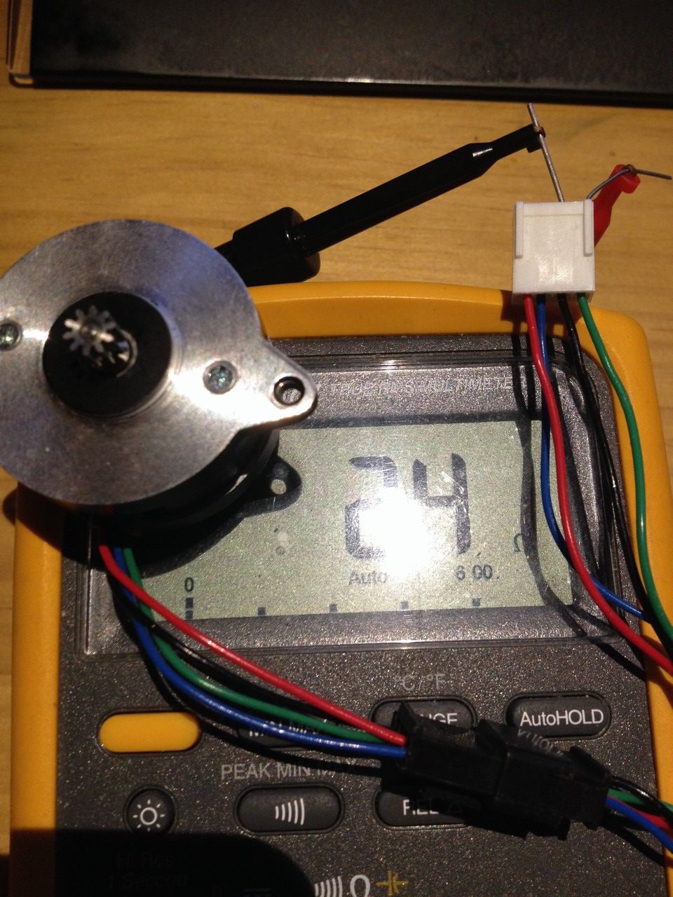
@dc42 Same measurement, same wiring like other picture but just more clear in view.
Hurray the stepper is rotating!!! The only thing i changed today was that i removed the (not needed) steps per mm in the config file from the Y and Z axis. This has nothing to do with E axis right?!
BUT appearantly , how in the hell this is possible i dunno, it fucked up the pancake steppers. Im completely stunned here and i would like to ask DC42 to try and replicate this. the more values registered under Y and Z axis must have crazed the system in some kinda really odd way.
Wow unbelievable, but im so happy it works now, jeeeez im speechless. -
@jerolee , I am only trying to help you out. My final comment is to look at the section of my config file below. The first extruder is a 20mm LDO pancake, the second extruder is a 17mm LDO pancake. They are both driving a version of the Orbiter extruder.
; *** Motion Settings *** ; M566 X400 Y400 Z8 A8 C2 E300:300:300:300 ; Set maximum instantaneous speed changes (mm/min) M203 X35000 Y35000 Z1200 A1200 C5000 E3600:7200:3600:5000 ; Set maximum speeds (mm/min) M201 X6000 Y6000 Z400 A400 C400 E600:800:600:5000 ; Set accelerations (mm/s^2) ;M593 F48 ; cancel ringing at 50Hz (https://forum.e3d-online.com/threads/accelerometer-and-resonance-measurements-of-the-motion-system.3445/) ; ; *** Drive Currents *** ; ;M906 X2000 Y2000 Z1330 C400 E1000:1680:1680:1380 I30 ; motor currents (mA) maxes M906 X1400 Y1400 I30 M906 E1200:650:500:1380 I10 M906 A700 C400 I10 M906 Z1250 I70 ; M84 S120 ; Set idle timeout``` For the 20mm LDO pancake, I have the current set at 1200 mA. I also have a lower "maximum instantaneous speed change. I hope this helps. -
@generisi
Hi, i appreciate your help ofcourse.Good news mate, after i removed the values from Y and Z for the other motors on that axis in the config file, so only 1 value for Y and 1 value for Z, after upload and reset the pancake extruder WORKED!!!
It has nothing to do with the wiring but appearantly the values from Y and Z in the config file did some really odd magic preventing the 36mm round pancake to rotate. It did not bother a NEMA17I ask DC42 to try and replicate this oddly behaviour as i gues its a very interesting conflict somewhere??
So my problem is solved and im a happy camper.
M584 X0 Y1:4 Z2:5:6:7 E3 ; set drive mapping
M671 X-60:-60:660:660 Y-48:378:378:-48 S7 ; set the coordinates of the 4 Z-axis drivers
M350 X16 Y16 Z16 E16 I1 ; configure microstepping with interpolation
M92 X80.03 Y79.84 Z1619.80 E704.00 ; set steps per mm
M566 X900.00 Y900.00 Z60.00 E300.00 ; set maximum instantaneous speed changes (mm/min)
M203 X10000.00 Y10000.00 Z500.00 E1000.00 ; set maximum speeds (mm/min)
M201 X500.00 Y500.00 Z20.00 E500.00 ; set accelerations (mm/s^2)
M906 X800 Y800 Z800 E800 I30 ; set motor currents (mA) and motor idle factor in per cent
M84 S30 ; Set idle timeout -
@jerolee I am glad you figured it out. Check my settings for current, etc. they are working well for me so far.
Gene -
undefined jerolee has marked this topic as solved