Underextrusion only after corners
-
I'm experiencing an odd issue where underextrusion is happening only after corners on perimeters.
Material: 1.75mm Matterhackers Pro Series PLA
Setup:
-
Duet 3 with Toolboard
-
Bondtech LGX Extruder
-
Mosquito Hotend .4mm Vanadium Nozzle
Simplify3D
- .40 mm retraction
- .35 mm/s retraction Speed
- .2 mm layer height
- 40% infill
- 35% outline overlap
- 100% infill width
- 205C nozzle
- 60C bed
- 100% fan
- 60mm/s print speed
- 65% outline underspeed
- 80% solid infill underspeed
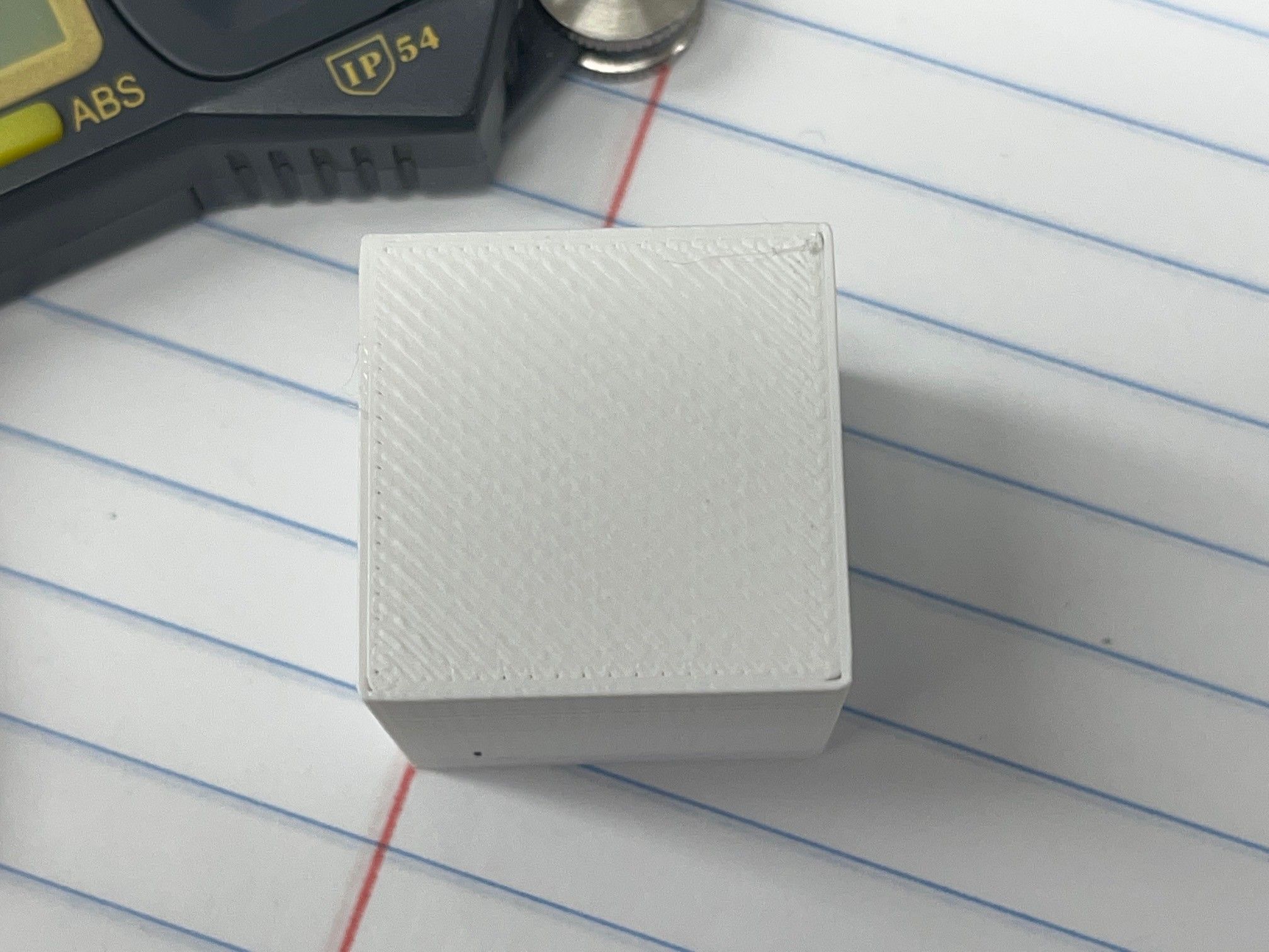
In the photo, the print on the left is with M572 D0 S0.1 and the right is M572 D0 S0. You can see the pressure advance helps prevent the bulging corners, but makes the corner underextrusion worse.
I calibrated my esteps by printing a 1-inch cube in vase mode with the extrusion width set to .48mm and adjusted until the 4 sides of the cube measured exactly .48mm.
What else could I try? Thanks in advance.

And here's my config.g file if it helps:
; Miscellaneous M575 P1 S1 B57600 ; enable support for PanelDue G4 S4 ;dwell ; General preferences G90 ; send absolute coordinates... M83 ; ...but relative extruder moves M550 P"TXT Stacker 2" ; set printer name ; Network M552 P0.0.0.0 S1 ; enable network and acquire dynamic address via DHCP M586 P0 S1 ; enable HTTP M586 P1 S0 ; disable FTP M586 P2 S0 ; disable Telnet ; Drives M569 P0.0 S1 ; physical drive 0.0 goes forwards M569 P0.1 S1 ; physical drive 0.1 goes forwards M569 P0.2 S0 ; physical drive 0.2 goes backwards M569 P20.0 S1 ; physical drive 20.0 goes forwards M584 X0.0 Y0.1 Z0.2 E20.0 ; set drive mapping M350 X32 Y32 Z32 E16 I1 ; configure microstepping with interpolation M92 X145.395 Y145.402 Z3200 E400.00 ; set steps per mm was M92 X146.1 Y146.1 Z3200 E400.00 M566 X900.00 Y900.00 Z18.00 E600.00 ; set maximum instantaneous speed changes (mm/min) M203 X12000.00 Y12000.00 Z600.00 E1200.00 ; set maximum speeds (mm/min) M201 X400.00 Y400.00 Z100.00 E3000.00 ; set accelerations (mm/s^2) was z50 M906 X1000 Y1000 Z1000 E450 I30 ; set motor currents (mA) and motor idle factor in per cent M84 S30 ; Set idle timeout ; Axis Limits M208 X0 Y-45 Z-2 S1 ; set axis minima M208 X490 Y330 Z645 S0 ; set axis maxima ; Endstops M574 X1 S1 P"!io1.in" ; configure active-low endstop for low end on X via pin io0.in with pullup resistor ;M574 X2 S1 P"!io3.in" ; configure active-low endstop for low end on X via pin io0.in with pullup resistor M574 Y1 S1 P"!io2.in" ; configure active-low endstop for low end on Y via pin io1.in with pullup resistor ;M574 Y2 S1 P"!io4.in" ; configure active-low endstop for high end on Y via pin io1.in with pullup resistor M574 Z1 S2.2 ; configure Z-probe endstop for low end on Z ;M574 E6 S1 P"!io5.in" ;Filament sensor switch ; External Triggers M950 J3 C"io5.in" ;creates J19 pin for io5 filament sensor M581 P3 T1 S1 R1 ;filament sensor: P pin, t Trigger 1, S logic, R while printing only ; Z-Probe M558 P8 C"20.io0.in" H1.5 F100 T6000 A5 ; set Z probe type to switch and the dive height + speeds G31 P500 X0 Y21.2 Z.94 ; set Z probe trigger value, offset and trigger height M557 X0:490 Y0:325 P10:7 ; define mesh grid ; 3-point Bed leveling ; Z probe has a Y offset ot 21.1mm ; back left (72,330) ; back right (400,330) ; front middle (236,75) ; thread pitch M4 X 0.7mm M671 X72:400:236 Y330:330:75 P0.7 ; Heaters M308 S0 P"temp0" Y"thermistor" T100000 B4138 ; configure sensor 0 as thermistor on pin temp0 M950 H0 C"out0" T0 ; create bed heater output on out0 and map it to sensor 0 M307 H0 B0 R0.160 C880.7 D2.62 S1.00 V23.7 ; disable bang-bang mode for the bed heater and set PWM limit M140 H0 ; map heated bed to heater 0 M143 H0 S120 ; set temperature limit for heater 0 to 120C M308 S1 P"20.temp0" Y"thermistor" T100000 B4680 C6.455513e-8 ; configure sensor 1 as thermistor on pin 20.temp0 M950 H1 C"20.out0" T1 ; create nozzle heater output on 20.out0 and map it to sensor 1 M307 H1 B0 R2.925 C170.4 D6.59 S1.00 V23.5 ; disable bang-bang mode for heater and set PWM limit M143 H1 S450 ; set temperature limit for heater 1 to 450C ; Fans M950 F0 C"20.out1" Q500 ; create fan 0 on pin 20.out1 and set its frequency M106 P0 S0 H-1 ; set fan 0 value. Thermostatic control is turned off M950 F1 C"20.out2" Q500 ; create fan 1 on pin 20.out2 and set its frequency M106 P1 S1 H1 T45 ; set fan 1 value. Thermostatic control is turned on M950 F2 C"out7" Q500 ; create fan 2 on pin out7 and set its frequency (for LED) M106 P2 S0 H-1 C"LED" ; set fan 2 value. Thermostatic control is turned off ; Tools M563 P0 S"Main Tool" D0 H1 F0 ; define tool 0 G10 P0 X0 Y0 Z0 ; set tool 0 axis offsets G10 P0 R0 S0 ; set initial tool 0 active and standby temperatures to 0C ; Filament Sensor ;M591 D0 P1 C"!io5.in" S1 ;D0 = Extruder 0, P1 = Signal high when filement present, C = pin name, S1 = filament monitoring enabled ; Custom settings are not defined T0 ;select tool 0 -
-
Increase the flow;)
Dont measure the Esteps with a single wall -
@pcr How do you like to measure the esteps? I get similar numbers using two walls.
-
@p8blr i do it with the 100mm extrusion length. Then I look that my top layer is closed. Your top layer still have gaps
-
Indeed. Looks like a bit of underextrusion in general. Calibrate your extruder.
https://duet3d.dozuki.com/Guide/Ender+3+Pro+and+Duet+Maestro+Guide+Part+4:+Calibration/40#s165
-
I used calipers to measure out 100mm of filament and adjusted my esteps accordingly. My top layer does not have those gaps like before, and maybe it's even a little overfilled. However, the cube I printed measures accurately to the 3D model, only being +.02mm too big in X, Y, & Z.
Unfortunately, as you can see below I am still experiencing the gaps in the corners. Any other ideas?

-
@p8blr said in Underextrusion only after corners:
M572 D0 S0.1
0.1 is actually quite a lot of pressure advance for a direct drive. For instance, my best results with a Titan Aero is 0.025.
Have you gone through a tuning process to identify your correct PA value yet?
https://duet3d.dozuki.com/Wiki/Pressure_advance
As for the slight over extrusion now, yes that could be the case. I'm not a S3D user, but there should be a place to specify the actual filament diameter as measured and to tweak the flow rate slightly. It's not uncommon to use ~95% slicer flow rate to get clean looking prints.
-
@p8blr might also be worth checking your infill overlap percentage in the slicer (note that you may need to adjust this when you change pressure advance)
-
@phaedrux I have yes, but I ran another test:
{REPLACE "; layer 5" "M572 D0 S0.01\n; layer 5" } {REPLACE "; layer 10" "M572 D0 S0.02\n; layer 10" } {REPLACE "; layer 15" "M572 D0 S0.03\n; layer 15" } {REPLACE "; layer 20" "M572 D0 S0.04\n; layer 20" } {REPLACE "; layer 25" "M572 D0 S0.05\n; layer 25" } {REPLACE "; layer 30" "M572 D0 S0.06\n; layer 30" } {REPLACE "; layer 35" "M572 D0 S0.07\n; layer 35" } {REPLACE "; layer 40" "M572 D0 S0.08\n; layer 40" } {REPLACE "; layer 45" "M572 D0 S0.09\n; layer 45" } {REPLACE "; layer 50" "M572 D0 S0.10\n; layer 50" } {REPLACE "; layer 55" "M572 D0 S0.11\n; layer 55" } {REPLACE "; layer 60" "M572 D0 S0.12\n; layer 60" } {REPLACE "; layer 65" "M572 D0 S0.13\n; layer 65" } {REPLACE "; layer 70" "M572 D0 S0.14\n; layer 70" } {REPLACE "; layer 75" "M572 D0 S0.15\n; layer 75" } {REPLACE "; layer 80" "M572 D0 S0.16\n; layer 80" } {REPLACE "; layer 85" "M572 D0 S0.17\n; layer 85" } {REPLACE "; layer 90" "M572 D0 S0.18\n; layer 90" } {REPLACE "; layer 95" "M572 D0 S0.19\n; layer 95" } {REPLACE "; layer 100" "M572 D0 S0.20\n; layer 100"} 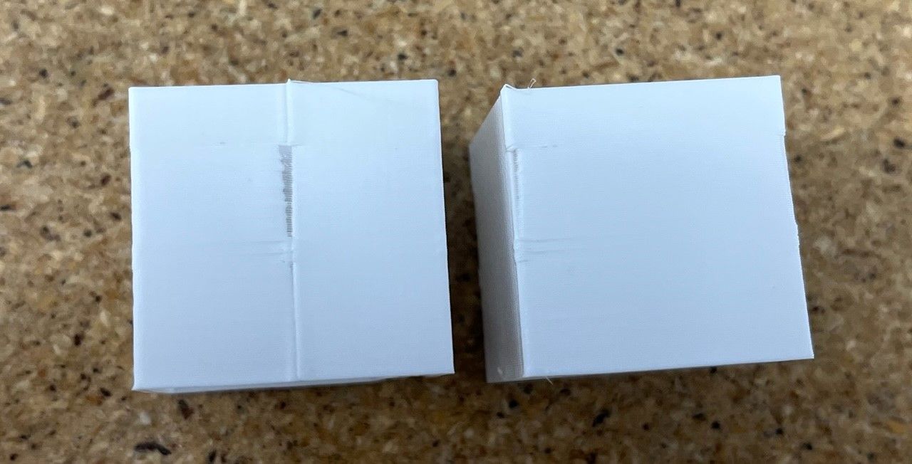
It seems like the start/stop gap begins right around .1 so that's where I've left it. Although, I've never really been able to get a nice looking start/stop. I've played with extra restart distance and coasting distance and the don't make much of a difference in my testing.
Yes I should have measured my filament first, I'll do another test with that added in Simplify3D to see if the over extrusion goes away.
-
0.1 may still be quite a lot for a direct drive, I'd suggest doing another test with values ranging closer around 0.1. Perhaps start with 0.01 up to 0.1.
What range of values did you use in the test?
-
@phaedrux .01 to .2 in .01 increments.