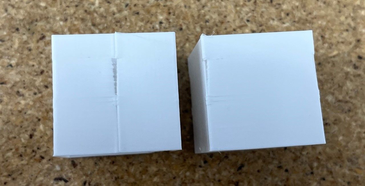
Underextrusion only after corners
-
Increase the flow;)
Dont measure the Esteps with a single wall -
@pcr How do you like to measure the esteps? I get similar numbers using two walls.
-
@p8blr i do it with the 100mm extrusion length. Then I look that my top layer is closed. Your top layer still have gaps
-
Indeed. Looks like a bit of underextrusion in general. Calibrate your extruder.
https://duet3d.dozuki.com/Guide/Ender+3+Pro+and+Duet+Maestro+Guide+Part+4:+Calibration/40#s165
-
I used calipers to measure out 100mm of filament and adjusted my esteps accordingly. My top layer does not have those gaps like before, and maybe it's even a little overfilled. However, the cube I printed measures accurately to the 3D model, only being +.02mm too big in X, Y, & Z.
Unfortunately, as you can see below I am still experiencing the gaps in the corners. Any other ideas?

-
@p8blr said in Underextrusion only after corners:
M572 D0 S0.1
0.1 is actually quite a lot of pressure advance for a direct drive. For instance, my best results with a Titan Aero is 0.025.
Have you gone through a tuning process to identify your correct PA value yet?
https://duet3d.dozuki.com/Wiki/Pressure_advance
As for the slight over extrusion now, yes that could be the case. I'm not a S3D user, but there should be a place to specify the actual filament diameter as measured and to tweak the flow rate slightly. It's not uncommon to use ~95% slicer flow rate to get clean looking prints.
-
@p8blr might also be worth checking your infill overlap percentage in the slicer (note that you may need to adjust this when you change pressure advance)
-
@phaedrux I have yes, but I ran another test:
{REPLACE "; layer 5"   "M572 D0 S0.01\n; layer 5"  }
{REPLACE "; layer 10"  "M572 D0 S0.02\n; layer 10" }
{REPLACE "; layer 15"  "M572 D0 S0.03\n; layer 15" }
{REPLACE "; layer 20"  "M572 D0 S0.04\n; layer 20" }
{REPLACE "; layer 25"  "M572 D0 S0.05\n; layer 25" }
{REPLACE "; layer 30"  "M572 D0 S0.06\n; layer 30" }
{REPLACE "; layer 35"  "M572 D0 S0.07\n; layer 35" }
{REPLACE "; layer 40"  "M572 D0 S0.08\n; layer 40" }
{REPLACE "; layer 45"  "M572 D0 S0.09\n; layer 45" }
{REPLACE "; layer 50"  "M572 D0 S0.10\n; layer 50" }
{REPLACE "; layer 55"  "M572 D0 S0.11\n; layer 55" }
{REPLACE "; layer 60"  "M572 D0 S0.12\n; layer 60" }
{REPLACE "; layer 65"  "M572 D0 S0.13\n; layer 65" }
{REPLACE "; layer 70"  "M572 D0 S0.14\n; layer 70" }
{REPLACE "; layer 75"  "M572 D0 S0.15\n; layer 75" }
{REPLACE "; layer 80"  "M572 D0 S0.16\n; layer 80" }
{REPLACE "; layer 85"  "M572 D0 S0.17\n; layer 85" }
{REPLACE "; layer 90"  "M572 D0 S0.18\n; layer 90" }
{REPLACE "; layer 95"  "M572 D0 S0.19\n; layer 95" }
{REPLACE "; layer 100" "M572 D0 S0.20\n; layer 100"}
It seems like the start/stop gap begins right around .1 so that's where I've left it. Although, I've never really been able to get a nice looking start/stop. I've played with extra restart distance and coasting distance and the don't make much of a difference in my testing.
Yes I should have measured my filament first, I'll do another test with that added in Simplify3D to see if the over extrusion goes away.
-
0.1 may still be quite a lot for a direct drive, I'd suggest doing another test with values ranging closer around 0.1. Perhaps start with 0.01 up to 0.1.
What range of values did you use in the test?
-
@phaedrux .01 to .2 in .01 increments.