Anybody wants a stepper motor analyzer?
-
@dogma2k, the current readings seem have have offset. You may want to reset it in the Settings screen with the motor disconnected (that is, zero current).
-
@zapta said in Anybody wants a stepper motor analyzer?:
- Using an insulated 10mm width double tape on the back of the PCB, at the marked areas. E.g. https://www.amazon.com/Adhesive-10mmx25mx0-25mm-Thermally-Conductive-Computer/dp/B075FRPXQ5 . I also apply it between the PCB and the PICO, just in case.
I had double-sided tape in between. Wasn't enough
https://www.amazon.de/gp/product/B08YJK6L1T/ref=ppx_yo_dt_b_asin_title_o07_s00?ie=UTF8&psc=1
It didn't matter, it went well, it was just fun to find the fault ...- Pre cutting the servo connectors pins such that they don't protrude at the back of the connector. This is the trimming jig I use https://github.com/zapta/simple_stepper_motor_analyzer/blob/main/3d/connector_trim_jig.stl
That would probably have been the best had I done that
BTW, it should be ok to connect multiple analyzers to the same servo since the sensors serial resistance is very low.
Even more? I already need 4 pieces because I have 2x X steppers and 2x Y steppers.
The small OLED is also not yet in operation for the filament flow meter, because I haven't had time to get the Arduino UNO readyI still have a problem that as soon as the motors are working, the display does not react at all or almost not at all.
If the motors are switched off with M84 then you can use the display properly.
How come that -
@dogma2k said in Anybody wants a stepper motor analyzer?:
I still have a problem that as soon as the motors are working, the display does not react at all or almost not at all
Can you explain what what you mean? Chan you change pages? Do you see any reading on the main page?
Per my previous post, it seems that your sensors need zero calibration. This is done in the Settings page (accessible from the main page) with the motor disconnected.
-
@zapta said in Anybody wants a stepper motor analyzer?:
@dogma2k said in Anybody wants a stepper motor analyzer?:
I still have a problem that as soon as the motors are working, the display does not react at all or almost not at all
Can you explain what what you mean? Chan you change pages?
Would you have to recognize property in the two videos what I mean (if not, I'll make better ones)
If no stepper has been used, I can switch through the menus, as soon as the stepper has moved once, the displays can no longer be operated.I'll do the zeroing with disconnected stepper afterwards when I'm back.
-
@dogma2k I had this issue on my first analyzer I boiled it down to a couple things.
As @zapta mentions, if you don't cut the pins there may just enough bite into the back of the LCD which shorts things out. I pulled the connectors out, recut, and used some 3M VHB to secure the LCDs.
Finally, double check the castellated pins on the PICO and make sure they're solid. If you used a thicker adhesive behind the PICO it might prevent good connections.
-
@th0mpy said in Anybody wants a stepper motor analyzer?:
@dogma2k I had this issue on my first analyzer I boiled it down to a couple things.
How can you reduce the choice, I really don't have a clue about it yet.
I took the APPLICATION.uf2 file from the temp directory on github, was it wrong?Finally, double check the castellated pins on the PICO and make sure they're solid. If you used a thicker adhesive behind the PICO it might prevent good connections.
Now the analyzers just don't run properly when the steppers are moving.
So it is more as if the Pico does not have enough power to process the incoming data quickly enough -
@dogma2k ,
-
Do you have the same problem on all four analyzer or just a few?
-
If you power the analyzers from a power supply on your printer, I suggest, as an experiment, to power one of them from a regular USB 5V charger and see if the problem persists.
-
-
Hey
Is it possible to indicate layer shifts with this analyser?
Richard -
@gruna-studio, that a good question. I guess it depends on the cause. E.g.
Intermittent wiring connection - It detects idling and electrical stepping error events so will probably detect.
Low current/torque due to an high speed - it will probably diagnose it in the current vs speed histogram page.
Mechanical binding - I am not sure about that. May need to research how that condition is reflected on the electrical signals. Also, the analyzer measures only current, monitoring also the stepper voltage may help here.
-
@zapta said in Anybody wants a stepper motor analyzer?:
@dogma2k ,
- Do you have the same problem on all four analyzer or just a few?
Yes all four analyzer have the same problem.
- If you power the analyzers from a power supply on your printer, I suggest, as an experiment, to power one of them from a regular USB 5V charger and see if the problem persists.
I'll try, but don't have much hope because I've already built a 24V / DC to 5V / DC power supply into the case
Or could it be because of the APPLICATION.uf2 file I used from the temp folder in github?
-
@zapta and everyone else who has an idea
")
Today I had some time to deal with the problem a little more intensively.The result is that it doesn't matter how I supply the analyzer with voltage
1 analyzer -> everything OK (if stepper on or off)
2 Analyzer -> everything OK (if stepper on or off)
3 Analyzer -> if the stepper is off then everything is OK, if the stepper is on it does not immediately become sluggish but after approx. 10 seconds all of them are no longer really operable
4 Analyzer -> if the stepper is off then everything is OK, when the stepper is on it is immediately sluggish and inoperableThe combination of which analyzers are used together does not matter, it always gets the above result
When I use two different voltage sources, the above result counts.Are there any influences that can arise if more than 2 are switched on at the same time. Diodes on each of the + 5V / DC wires of the Pico may
-
@dogma2k, that sounds bad. Everything should work.
- Did you make any hardware changes to the board?
- Are you the exact same components in the original schema?
- What TFT module are you using?
- What version of the firmware UF2 file do you use?
The original schema is here
https://github.com/zapta/simple_stepper_motor_analyzer/blob/main/kicad/stepper_analyzer.pdfThe original firmware is here
https://github.com/zapta/simple_stepper_motor_analyzer/releases/download/F1.0.4/APPLICATION.uf2If you want, you can send me one analyzer (to the US) and I will look at it and send you back.
-
@dogma2k is your PSU powerful enough to supply current to all 4 Picos and LCD screens? Colour TFT screens draw quite a lot of current.
Duet WiFi hardware designer and firmware engineer
Please do not ask me for Duet support via PM or email, use the forum
http://www.escher3d.com, https://miscsolutions.wordpress.com -
@dc42
I hope so. Both PSU have 5V/DC 5A -
Anyone have an idea? Something like soldering a diode?
It would be a shame if I had to take it all apart again because it doesn't work
PS it may be that an analyzer is defective (or the engine). Yes, I know I didn't zero it
-
@dogma2k said in Anybody wants a stepper motor analyzer?:
Anyone have an idea?
What cable or cables are you using to power them?
A lot of cheap USB cables are really for data only and have ludicrously thin cores for the power connections, causing serious voltage drops as soon as you try to run anything that takes significant current.
I've even had ones advertised as "high current" / "Heavy duty" that will not run USB devices that need 200 - 300mA.
Oddly enough, the early (typically cream coloured) ones I have work fine!
Robert J.
Printers: Overlord pro, Kossel XL+ with Duet 6HC and "Frankentron", TronXY X5SA Pro converted to E3D toolchange with Duet 6HC and 1LC toolboards.
-
@dogma2k, can you swap the connections of two analyzers to see if the problem follows the stepper or the analyzer?
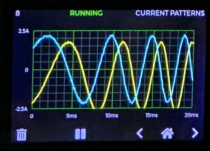
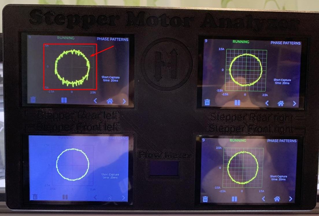
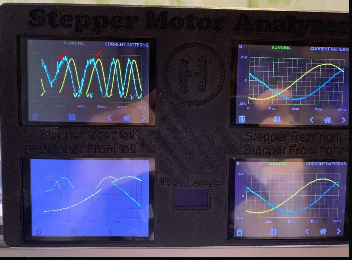
BTW, some of the artifacts, but not the noise you marked with arrows, are due to the screen being refreshed during the camera's exposure. You can pause the analyzer (using the || button at the bottom) if you want to avoid it.
-
@rjenkinsgb
At the moment, the power supply comes from a 5V / 5A power pack with 2x1mm² wires to the analyzer housing. In the housing, USB cables are used to distribute to the analyzers.The cables to and from the analyzer for the motors are LIYCY-OB 4x0.5mm² (i.e. shielded cable)
However, I think that the cross-section of the eagle of the USB cable is sufficient. Because the problem only occurs when more than 2 analyzers work at the same time with active engines (with 3 it gets worse over time)
However, I noticed that if I press a button longer with 4 active analyzers, the display then reacts. Just not with the analyzer at the top left, it even switches back and forth on its own
-
@zapta said in Anybody wants a stepper motor analyzer?:
@dogma2k, can you swap the connections of two analyzers to see if the problem follows the stepper or the analyzer?
I can at least swap the analyzers to see if the noise moves with it. But only tonight
BTW, some of the artifacts, but not the noise you marked with arrows, are due to the screen being refreshed during the camera's exposure. You can pause the analyzer (using the || button at the bottom) if you want to avoid it.
That with the II is a good tip.
Another question, I just have the APPLICATION.uf2 from https://github.com/zapta/simple_stepper_motor_analyzer/tree/main/temp
taken and copied. Is this still a beta version or is it already stable? -
@dogma2k , I am not sure what is in that temp dir.
This is the latest stable release of the firmware
https://github.com/zapta/simple_stepper_motor_analyzer/releases/tag/F1.0.4