Best way to increase rod spacing without 3D printed parts?
-
What would be the best way to increase the rod spacing of the SE without 3D printed parts? (I want to avoid the inherent imprecision and stiffness of melted plastic).
Would lasercut 2mm aluminum be enough to provide enough stiffness? Don't have access to affordable CNC milled parts, but lasercutting would be cheap enough around here. CNC bending wouldn't be an issue either. Thinking of a bracket with 90 deg bends to provide additional stiffness.
Goal would be to make room for an Orbiter 2.0 to be mounted with a shorter adapter as my current solution turns out to be a bit top-heavy.
-
@bberger
I would prefer FR4 over aluminum, that's the same material the SE is made off.
It would spare the extra work/cost of bending (and I could cut it myself with a CO2 laser)
-
@o_lampe I would fear that FR4 may not be stiff enough. I already am a bit at the limit the SE board can handle (large delta, 15k-25k acc - depending on the print). I do get gorgeous looking prints off it, but rigidity starts to become an issue. Especially with my current top-heavy mounting of the Orbiter (if I apply a little bit of pressure on the extruder with my index finger I can see the board bend and the nozzle tilt a little while the rods stay in position without any deformation).
Currently using the 3 inner holes to mount the Orbiter spacer and would the also like to re-use the current magball mountpoints for stabilizing the extruder. I could possibly also go for 6 additional rods to stabilize it, but I'm a bit concerned about the added weight of 6 rods and 12 magballs..
-
If I understand things correctly, why not implement a flying-extruder mount for the Orbiter? That way you everything remains as it was designed and intended to work.
3mm
-
@3mm because I want to get rid of the flying extruder.
I have hard mounted the Orbiter v2 on my Smart Effector with an approx 7cm adapter and prints come out insanely beautifully compared to my (genuine) BMG flying extruder (with only 15cm bowden).
I have way less ringing, can run 5k accel / 600 jerk / 100-150mm/s, 0.015 PA, 0.6mm retractions and no input shaping with barely any artifacts.. (I had to run 70mms, 3k accel, 50Hz DDA, 300 jerk, 1.5mm retractions to get any resemblance of a good looking print on my flying BMG before, I contribute that to the bowden tube yanking on the SE, I doubt that's the 150g saving on mass of the flying extruder..) - and also that 7cm "lever" with the mass of the motor up that high has me a bit concerned..
I'm currently prototyping some 80mm adapters in PLA-CF, trying to keep them flat so it can possibly be laser cut / milled out of Alu/CF in the future.
I'm not after speed benchys, but more after rapid prototyping..
-
@bberger please can you tell me what would be a suitable rod spacing to accommodate a Orbiter 2.0 extruder, so that we can plan a future version of the Smart Effector. I recall thinking that about 70mm spacing would be needed to accommodate the Orbiter 1.5.
Duet WiFi hardware designer and firmware engineer
Please do not ask me for Duet support via PM or email, use the forum
http://www.escher3d.com, https://miscsolutions.wordpress.com -
@dc42 said in Best way to increase rod spacing without 3D printed parts?:
@bberger please can you tell me what would be a suitable rod spacing to accommodate a Orbiter 2.0 extruder, so that we can plan a future version of the Smart Effector. I recall thinking that about 70mm spacing would be needed to accommodate the Orbiter 1.5.
I would gladly do that if I knew.. I'm too unskilled in CAD to draw a definite conclusion of my drawings.
But aside from changing the smart effector design - maybe offering an adapter for ~80mm rod spacing would be a better option if that doesn't halt the planning/production of the toolboard effector? I fear that the PCB board's structural capabilities would be a problem anyways if it stays at 2mm.
I was reading up on the E-Modulus of various materials to help me in a direction for my adapter design and found a ~4 GPa figure for FR4. For comparison: ABS is ~3, carbon reinfored PETG is about ~7GPa, Aluminum is ~100GPa. Carbon reinforced, printed PLA (like Extrudr Green TEC Pro Carbon, don't know the figure of other materials by memory) with 100% infill along the printed layers is ~7.5GPa in the same ISO test conditions.
I'm already kind of hitting the limits of what I'm comfortable with the smart effector PCB. I'd go as far as to say that even shrinking the SE and adding an adapter to begin with could be a sensible option given that Rev3 already frees up space.
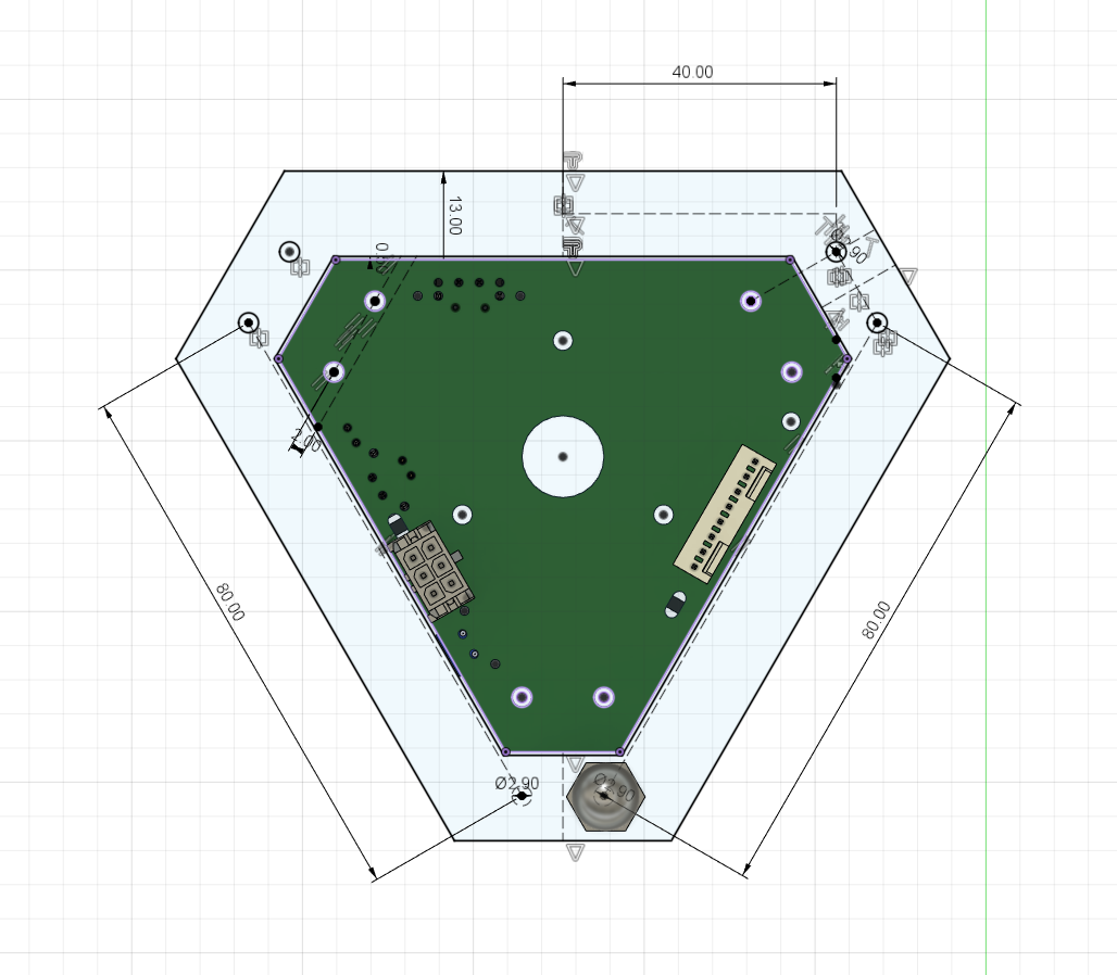
That ~80mm figure is btw what I came up with when adding 12mm offset to the current effector outline while keeping the 12mm distance between the magball holes on each edge.
I'll see how that goes clearance wise hopefully next weekend (this weekend is blocked due to my daughter's 2nd birthday commodities) and report back. 440mm Haydn arms in a Predator frame.
-
@dc42 PS: if at all possible - mounting holes for the new mosquito/phaetus/e3d/ would be a welcome bonus. Aside from the E3D V6 and Revo the M12 screw mount seems to have died..
-
This is what I came up with so far (3D Printed)...
Should be good enough for a prototype.
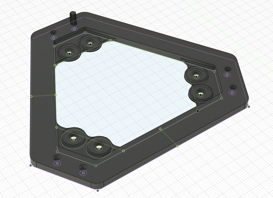
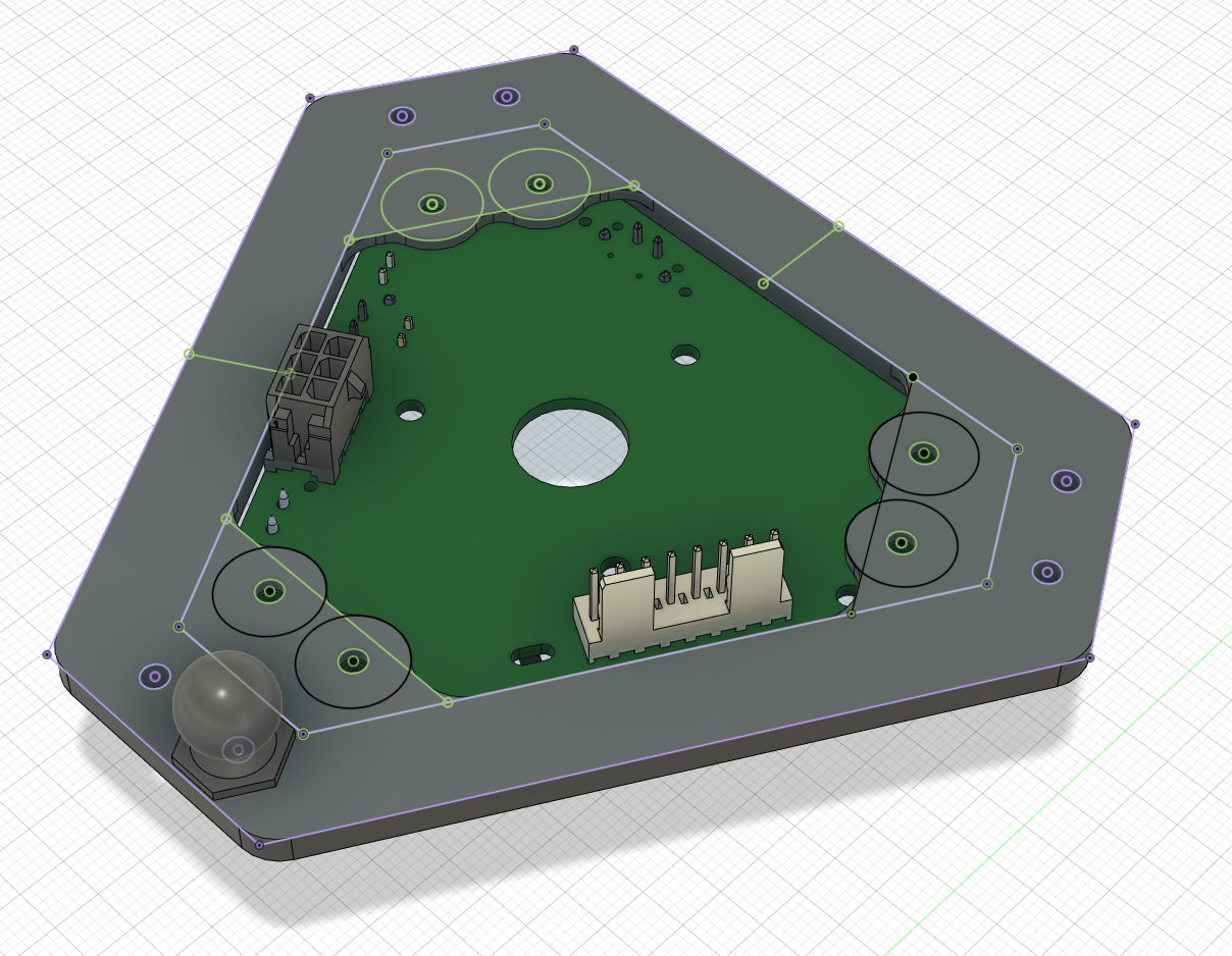
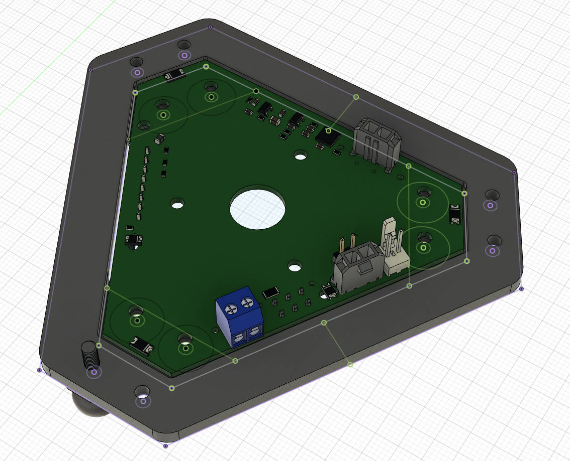
//Edit: way too soft/flexible, even in PLA-CF and 6.5mm thickness. Needs more rigidity..
-
@dc42 btw. @NexxCat has made a full Fusion 360 assembly (with joints, Smart Effector, 440mm Haydn arms, Delta Kinematics, ..).
I have no idea how (yet), but in principle it's just a matter of slapping the Orbiter/LGX Lite/whatever extruder on top of the smart effector and play around with the SE size to see if it clears.
-
@bberger said in Best way to increase rod spacing without 3D printed parts?:
@3mm because I want to get rid of the flying extruder.
I have hard mounted the Orbiter v2 on my Smart Effector with an approx 7cm adapter and prints come out insanely beautifully compared to my (genuine) BMG flying extruder (with only 15cm bowden).
I have way less ringing, can run 5k accel / 600 jerk / 100-150mm/s, 0.015 PA, 0.6mm retractions and no input shaping with barely any artifacts.. (I had to run 70mms, 3k accel, 50Hz DDA, 300 jerk, 1.5mm retractions to get any resemblance of a good looking print on my flying BMG before, I contribute that to the bowden tube yanking on the SE, I doubt that's the 150g saving on mass of the flying extruder..) - and also that 7cm "lever" with the mass of the motor up that high has me a bit concerned..
I'm currently prototyping some 80mm adapters in PLA-CF, trying to keep them flat so it can possibly be laser cut / milled out of Alu/CF in the future.
I'm not after speed benchys, but more after rapid prototyping..
HI. Sounds like you have a better handle on things than I do. I'm still dealing with a few significant artifacts, however, my prints became signficantly better when I implemented my own (OScad) BMG flying-extruder for my SmartEffector and linear-rail magball PCB adapters. I designed my linear-rail MagBall adapters to use the SE effector MagBall PCB. My Bowow tube is about 18cm long. But I'm not seeing a any major ringing, but anything above a specific height gets mangled.
I'd be interested to see your flying-extruder configuration if you happen to have any photos of it before you chucked-it out?
In any case, good luck with your strategy, sounds interesing.
3mm
-
@dc42
With all the different heatsink mounting options, it's probably best to remove the PCB-strain gauge sensor and go for a load cell inline with the heatsink?
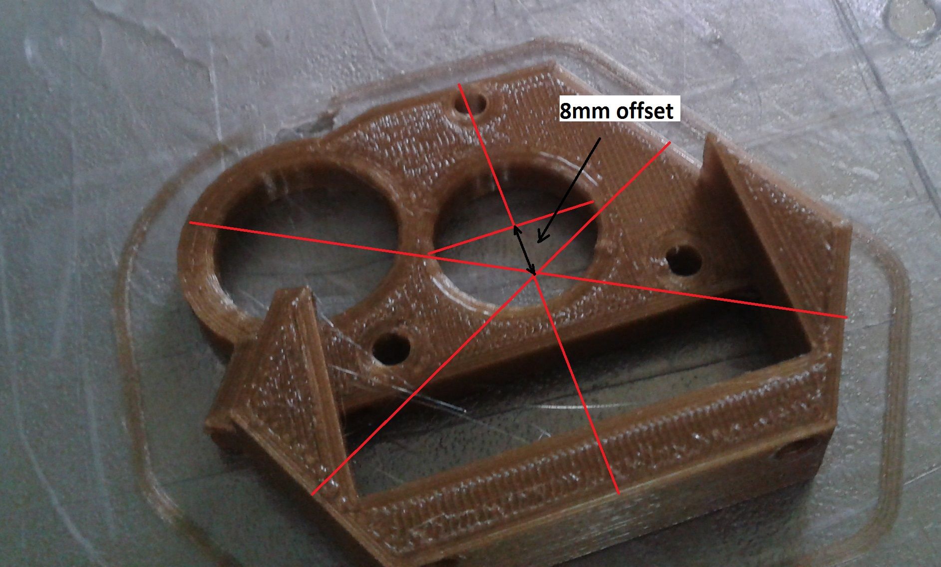
That would also offer the option to use an offset for the heatsink to mount eg. Sherpa Mini or Orbiters directly.
In case of the Sherpa Mini, it only takes 8mm offset and the rod spacing can stay the same.
-
@o_lampe SE v3 already moved from the PCB traces to resistors as strain gauge, which clears a lot of area.
-
@dc42 I can say that with 80mm rod spacing it comfortably clears the rods on a 380mm bed, delta radius 225mm, rod length 440mm when mounted flush with the top of the M12 threaded heatsink.
I'll puslish my (3D printed version) of the 80mm adapter sometime this week. Wanted to publish it today, but I've found a few inconviniences with mounting in my design that I want to get out of the way first.
The biggest problems with the 80mm spacing (which is about the minimum for an adapter if you want to keep the 12mm gap between the ball studs) and a direct drive mount actually is the Molex connector because there's actually only 1 orientation where it doesn't collide (as in: there's enough space to get the latch open) with the Orbiter V2. The white connector ideally should be spaced out too, but it isn't that big of a deal as there is no latch to open.
-
@bberger I have the same problem with increasing the 12mm gap but keeping 55mm arm spacing. My 'solution' is to cut the clip off the connector - I use a pre wired strain relieved molex plug which has a very tight fit, which I am sure is not going to come adrift.