Input Shaper Questions
-
I've been delving into tuning input shapers using the plugin, and I've made good progress. However, I've been guessing about parameters, algorithms and developing a comprehensive process. This thread could serve as a guide for others who have a lack of understanding.
-
May we have a brief explanation of IS algorithms, their drawbacks, and what situations you would pick one over the other?
-
It's mentioned that jerk should be just high enough to guarantee smooth curves. What are some basic values for that? My printer is a Voron V2.4 300x300 and I have jerk set to 720 mm/min for both X and Y. What jerk is appropriate for different modes? eg CoreXy, Cartesian, Delta etc?
-
Do you need to reanalyze resonance if you change accelerations and speed, or is a printer's resonance constant regardless of those variables?
-
Can we get a better explanation of damping factor? When analyzing resonance frequencies, what do we look for that would indicate that damping factor needs to be altered?
-
In the plugin there's a field for the number of samples. What's the maximum number of samples that is useful and what are the limitations of the toolboard's ability to record samples?
I'm sure I'll have more questions as time goes by, but hopefully this is a good start.
-
-
Since I do not have an accelerometer here is my learning
- for my Voron 2.4. 350x350 there is a strong resonance at 65mm/s in X-axis direction
- for my understanding the resonance frequency is independent of the acceleration
- the effects were strong waves at the test example for pressure advance: https://duet3d.dozuki.com/Wiki/Pressure_advance
- in the end it was mainly the correct adjustment of the jerk that prevented the waves. There seems to be too much and too little here
Here are my current values:
M566 X400.00 Y400.00 Z100.00 E3000.00 P1 ; set maximum instantaneous speed changes (mm/min) M203 X60000.00 Y60000.00 Z6000.00 E4000.00 ; set maximum speeds (mm/min) M201 X2500 Y2500 Z500.00 E4000.00 ; set accelerations (mm/s^2) M593 p"mzv" F46 ; input shaping M572 D0 S0.03 ; pressure advance -
@ctilley79 Man. I was hoping this question would get the needed attention. I believe everyone has these questions.
-
@ctilley79 I also played around with Input Shaper and found the EI3 Algorithm working the best but it's far off from what I see others do with klipper. So I'm wondering if I need to tune Jerk or something else correctly for it to work better or Duets Algorithms simply need more work.
-
@ctilley79 said in Input Shaper Questions:
I've been delving into tuning input shapers using the plugin, and I've made good progress. However, I've been guessing about parameters, algorithms and developing a comprehensive process. This thread could serve as a guide for others who have a lack of understanding.
- May we have a brief explanation of IS algorithms, their drawbacks, and what situations you would pick one over the other?
The main classes of IS algorithms supported by RRF are the ZVD series and the EI series. Both come in different orders depending on how many stages the acceleration or deceleration is split into. The higher the order, the wider the frequency band over which resonances are reduced; but the more time is spent accelerating or decelerating, which slows down the print.
You can see the effectiveness of the various algorithms with respect to frequency by looking at the graphs at https://docs.google.com/spreadsheets/d/1R23r0KRFosGNWJEqsnCXL6ylpuayGqDvm8ocOszalV4/edit?usp=sharing. The ZV family give a U-shaped reduction about the centre frequency, with the U getting wider as the order is increased. The EI series give a wider rejection band, but with up to 5% ripples within that band. Note, those graphs don't all use the same damping factor.
- It's mentioned that jerk should be just high enough to guarantee smooth curves. What are some basic values for that? My printer is a Voron V2.4 300x300 and I have jerk set to 720 mm/min for both X and Y. What jerk is appropriate for different modes? eg CoreXy, Cartesian, Delta etc?
The optimum jerk doesn't depend directly on the kinematics, only on the printing speed and on the angles between line segments that the slicer generated when approximating curves.
- Do you need to reanalyze resonance if you change accelerations and speed, or is a printer's resonance constant regardless of those variables?
The printer's resonances don't depend on acceleration, although changing acceleration may change the degree to which resonances are excited.
- Can we get a better explanation of damping factor? When analyzing resonance frequencies, what do we look for that would indicate that damping factor needs to be altered?
Damping factor is not easy to estimate from the acceleration plots, however we hope to do this in a future version of the input shaping plugin. Klipper suggests use 0.1 as the default; however, if you have a strong resonance, my experience is that it is much better to set it to 0. I suspect that it's only the low order shapers that benefit from using an accurate damping factor, and for the higher order shapers 0 may be a better default than 1.
- In the plugin there's a field for the number of samples. What's the maximum number of samples that is useful and what are the limitations of the toolboard's ability to record samples?
The longer the sampling time, the greater the frequency resolution. For example, to resolve to within 1Hz you need 1 seconds worth of samples, which for the tool board is about 1340 samples.
-
@baua1024 said in Input Shaper Questions:
@ctilley79 I also played around with Input Shaper and found the EI3 Algorithm working the best but it's far off from what I see others do with klipper. So I'm wondering if I need to tune Jerk or something else correctly for it to work better or Duets Algorithms simply need more work.
Try setting the damping factor to 0 instead of the default 0.1.
-
@dc42 thank you very much for the explanation. That clears things up a lot.
-
@dc42 Thanks for these explanations! I tried again all shapers with a value of 0 and 0.1 and didn't see a lot of a difference. I got to really good results now that I did these changes:
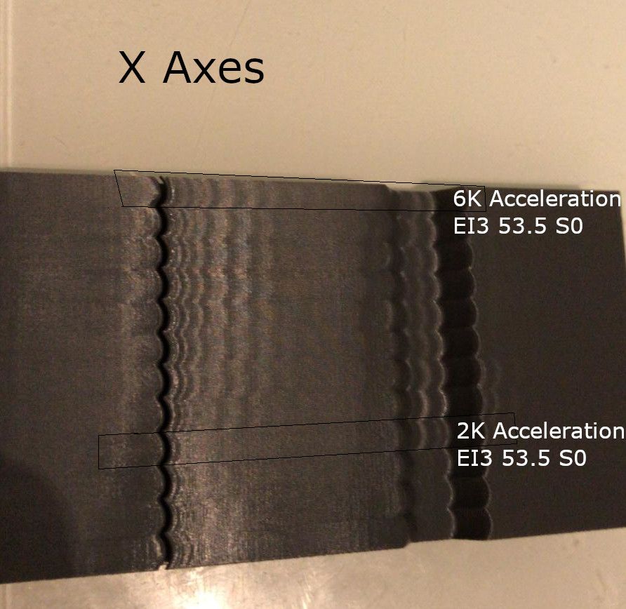
- Changed Acceleration on X from 3K to 6K didn't make it any worse but going down from 3K to 2K on Y made significant improvements.
- Jerk Values have been on 400 on X and Y and cause the printhead to take corners very harsh. Running 1000 now and the printhead moves a lot smother.
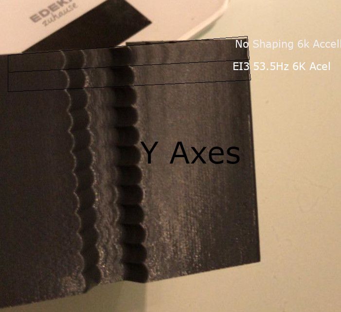
- I had two frequencies in my accelerometer data: 4.8Hz(x) and 53.5Hz(y). The 4,8 Hz didn't do a lot of improvement but the 53.5Hz helps a huge amount on the X Vibration. The resonance on Y access didn't really improve with input shaping but only with lower acceleration however the resonance introduced by X went significantly down.
Here a Ringing Tower with 140mms/s where I tuned different shapers with no Shaping at top.
Each segment is a different Shaper algorithm with S0 and S0.1. They all do a great job compared to no shaping:

This Ringing Tower uses only the EI3 53.5Hz S0 Shaper but is increasing Y Acceleration each layer. Best Result was at 2K. The Shaper seems to not affect Ringing on X Axes introduced by Y Axes Vibrations:

-
I have an accelerometer hooked up and working, but found that the output results were a bit inconsistent, depending on how the data was gathered.
I found that a very effective method involves using custom after-layer gcode insertions in Super Slicer. Basically, you set up whatever test print you want, make sure speed and acceleration are set sufficiently high to induce ringing. Then enter custom codes like this:
{if layer_num < 33}M593 P"none"
{else}M593 P"MZV" F{(layer_num)*1.5}
{endif}Vary the multiplier and layer number to sweep the range of frequencies you want to cover. Then, let it rip!
You can repeat the test print with the other shaper methods and see which one works best for you. I actually like MZV. It seems to be the best blend of effectiveness and minimal slowdown.
Find the Z height where you like the result best, and reference the formula (or gcode) to see which frequency this was. Then you can repeat the test, sweeping a narrower range of frequencies around your optimum.
Maybe I'll try this test with the damping factor as well.
-
"Damping factor is not easy to estimate from the acceleration plots, however we hope to do this in a future version of the input shaping plugin. Klipper suggests use 0.1 as the default; however, if you have a strong resonance, my experience is that it is much better to set it to 0. I suspect that it's only the low order shapers that benefit from using an accurate damping factor, and for the higher order shapers 0 may be a better default than 1."
I tried reading up on Input Shaping Methods and especially Damping factor for the better of last night.
Yet I'm still not sure what it's good for.
Is there a way to break it down in laymen terms for non-PhD people?
Things I absolutely didn't understand or I'm unsure about (which are fundamental things I suppose


- does it shift the timing of the shaper?
- does it affect the "amplitude" (agressiveness?) of the shaper curve?
- it has to do with elasticity of the system - correct?
- why would 0 be a better "default" than 1? Because we assume the system isn't stiff enough? Or because we assume the system is too stiff?
-
@bberger also: why would MZV be a better choice than ZVD when ZVD covers +/-15% and MZV only +/-4 during the same 1/freq runtime?
Why should I choose MZV over ZVD?