Corexyuv vs corexy idex
-
@randyl00123
The official way to remap axes during a toolchange is the tool definition line itself:M563 P1 S"U" D1 H2 X9 F3 ;Fan1 is thermostatically controlled, F3 is gcode controlled by tool P1//edit
X-axis is already mapped to drive 9,but is the driver number of "U" motor?
What about the V-axis? -
@o_lampe U is also a separate corexy hotend and uses motors 9 and 0 for U and V
-
@randyl00123 you can also map Y to a different axis
https://duet3d.dozuki.com/Wiki/M563 -
@o_lampe said in Corexyuv vs corexy idex:
@randyl00123
The official way to remap axes during a toolchange is the tool definition line itself:That's something new I've learned today - much more elegant than my solution.

-
@deckingman what was y our solution?
-
@randyl00123 said in Corexyuv vs corexy idex:
@deckingman what was y our solution?
??? Scroll up a bit - as per my posts of 7:41 and 7:49 this morning.
-
@deckingman Sorry, I was referring to the other person that said your solution was more elegant than his. I was wondering what his solution was. I always thought that tools had to be defined in config.g. I wasn't aware that m584 could be used in a macro file.
-
@randyl00123 Now I'm confused. I was the first to reply to your OP with a possible solution using M584. Then @o_lampe posted the official way of doing it using M563. So I then replied to @o_lampe to say that his idea of using M563 was much more elegant than mine. Forget about using M584 - it would work but it's messy and using M563 would be much better.
-
@deckingman said in Corexyuv vs corexy idex:
sing M58
The corexy and idex instructional pages truly suck. The instructions for configuring corexyuv states four motors, then go on to give M563 instructions for a different layout (corexyu). They say matrix without defining what the matrix IS. Anyway, after weeks of frustration, I FINALLY guessed and it worked. Here's the solution I came up with that WORKS for Corexyuv (Two independant corexy carriages on one X gantry using a Duet2 wifi and a duex5...
; Configuration file for Duet WiFi (firmware version 3)
; executed by the firmware on start-up
;
; Randy's corexy idex 26 January 2022; General preferences
M111 S1 ; Debugging
G21 ; Work in millimetres
G90 ; send absolute coordinates...
M83 ; ...but relative extruder moves
M555 P0 ; Set firmware compatibility to look like RepRap_Firmware to look like rrf
M404 N1.75 D0.6 ; Set nominal filament diameter to 1.75 and nozzle width to 0.4
M575 P0 B250000 ; Set baud rate for USB port for Octoprint
M575 P1 S1 B57600 ; enable support for PanelDue (Default B57600); Network
M550 P"Randy corexy idex" ; set printer name
M552 S1 ; enable network
M586 P0 S1 ; enable HTTP
M586 P1 S1 ; enable FTP
M586 P2 S0 ; disable Telnet
M575 P1 B57600 S1 ; Set auxiliary serial port baud rate and require checksum (for PanelDue); Drives
M569 P7 S0 ;Drive 7(XX7)
M569 P8 S0 ;Drive 8(XY8)M569 P0 S0 ;Drive 0(UX) change to a 1 for forwards
M569 P9 S1 ;Drive 1(UY);M569 P0 S0 ;Drive 0(UX) change to a 1 for forwards
;M569 P9 S1 ;Drive 1(UY)M569 P2 S0 ;Drive 2(ZRR5)
M569 P5 S0 ;Drive 5(ZCF2)
M569 P6 S0 ;Drive 6(ZRL6)M569 P3 S1 ;Drive 3(e0)
M569 P4 S1 ;Drive 4(e1);initial machine configuration
M584 X8 Y7 Z2:5:6 U9 V0 E3:4 P4 ;this one works! X0 and Y0 are corexy X carriage. 7,8 U carriage 2=ZRR5, 5=ZCF2,6=ZRL6M671 X300:120:-90 Y315:-60:315 F10 ;lead screws are located at drive 2 = back right corner, drive 5 at front center, drive 6 at left rear
M669 K5 ; select 5=corexyu 8=CoreXYUV mode
;Axis Limits
M208 S0 X331 Y208 U435.00 Z268.35 ;set axis maxima S0 means maxima V350 - V240
M208 S1 X-98 Y0 U0 Z-2.00 ;set axis minima S1 means minima V80
;endstops
M574 X1 S1 P"e0stop"
M574 U2 S1 P"xstop"
M574 Y2 S1 P"ystop" ;Y MAX active high endstop switch
;M574 Y2 S1 P"ystop" ;Y MAX active high endstop switchM574 Z2 S1 P"e1stop+zstop+duex.e2stop" ; configure active-high endstops for high end on Z
;M574 E0 S1 ;x filament sensor
;M574 E1 S1 ;U filament sensor; Heaters
M140 H0 ; map heated bed to heater 0
M308 S0 P"bedtemp" Y"thermistor" T100000 B4138 ; configure sensor 0 as thermistor on pin bedtemp
M950 H0 C"bedheat" T0 ; create bed heater output on bedheat and map it to sensor 0
M143 H0 S120 A2 ; set temperature limit for heater 0 to 120C
M307 H0 B0 R0.616 C164.1 D1.24 S1.00 V24.1
M570 S120 ;after a heater has been switched on, wait 120 seconds for it to get close to the set temperature. If it takes longer than this, raise a heater fault.M308 S1 P"e0temp" Y"thermistor" T100000 B4138 ; configure sensor 1 as thermistor on pin e0temp
M950 H1 C"e0heat" T1 ; create nozzle heater output on e0heat and map it to sensor 1
M307 H1 B0 S1.00 ; disable bang-bang mode for heater and set PWM limit
M143 H1 S275 A2 ; set temperature limit for heater 1 to 280CM308 S2 P"e1temp" Y"thermistor" T100000 B4138 ; configure sensor 2 as thermistor on pin e1temp
M950 H2 C"e1heat" T2 ; create nozzle heater output on e1heat and map it to sensor 2
M307 H2 B0 S1.00 ; disable bang-bang mode for heater and set PWM limit
M143 H2 S275 A2 ; set temperature limit for heater 2 to 280C;M305 P2 X101 ;Use thermocouple for heater P2// note for when I upgrade to a K type thermocouple
;show the MCU and stepper driver temperature, send the following commands:
M308 S10 Y"mcu-temp" A"MCU"
M308 S11 Y"drivers" A"Steppers";Tools
;T0 (X carriage)
M563 P0 S"X" D0 H1 F2 ; X0 Y1Fan0 is thermostatically controlled, F2 is gcode controlled by tool P0
;M563 P0 S"X" D0 H1 F2
G10 L1 P0 X0 Y0 Z0 ;X has no offsets
M568 P0 R240 S250 ;set standby temperature at 240 and active temperature at 250
;M568 P0 R0 S0 ;set standby temperature at 240 and active temperature at 250
M307 H1 B0 R2.572 C150.0 D7.50 S1.00 V24.0 ;X hotend tuning parameters
M950 F0 C"duex.FAN4" ;create fan 0 on pin duex.FAN4 because fan0 on duet is always on
M106 P0 T75 S255 H1 ;when heater 1(XHotend) reaches 75 Celcius, turn on Fan0 at 100% (0-255)
M950 F2 C"FAN2" ;H1 x part fan;capacitive sensor
M558 P5 C"!zprobe.in" H10 F100 T2000 A3 S-1 ;enable pullup resistor(^), invert input (!), (H)Dive height 10mm,
;probing feed rate100mm/min
;travel speed between probe points 2000mm/min, A2 -probe each point twice
;M558 P9 means BLTouch P10 is stall detect. C" " is the pin input name, H5 means drop 5mm between points,
;A3 means probe three times S-1 means average the three probe distances
G31 X-38.32 Y-16.15 Z1.00 ;initial offsets to the center of the zprobe from X nozzle, redefined in find_Z_range.g which is called from homeall.gT1 (U carriage)
;M563 P1 S"U" D1 H2 F3
M563 P1 S"U" F3 D1 H2 X3 Y1:4 ;Fan1 is thermostatically controlled, F3 is gcode controlled by tool P1 X mapped to U axis, Y mapped to Y axiswhere X=0, Y=1, Z=2, U=3 etc, not by driver number
;M563 P1 S"U" F3 D1 H2 X3 y4 ;Fan1 is thermostatically controlled, F3 is gcode controlled by tool P1 X mapped to U axis, Y mapped to Y axiswhere X=0, Y=1, Z=2, U=3 etc, not by driver number
G10 L1 P1 X0.0 y1.5 Z-2.15 ;use U_find_the_dot to tweak
;M568 P1 R0 S0 ;initial tool set and stanby temperatures
M568 P1 R240 S250 ;initial tool set and stanby temperatures
M307 H2 B0 R3.174 C186.4:172.2 D8.41 S0.50 V24.0
M950 F1 C"FAN1" ;create fan 1 on pin fan1
M106 P1 T75 S255 H2 ;when heater 2(UHotend) reaches 75 Celcius, turn on Fan1 at 100%
M950 F3 C"duex.FAN3" ;H2 u part fan;T2 (Copy mode)
;M563 P2 S"copy" D0:1 H1:2 X0:3 Y1:4 F2:3 ; define tool 2
;G10 P2 X50 Y0 U-50 S0 R0 ; set tool offsets and temperatures
;M567 P2 E1:1 ; set mix ratio 100% on both extruders
;M568 P2 S1 ; turn on mixing for tool 2;T3 (Mirror mode)
;M563 P2 S"Mirror" D0:1 H1:2 X0:3 Y1:4 F2:3 ; define tool 3
;G10 P2 X50 Y0 U-50 S0 R0 ; set tool offsets and temperatures
;M567 P2 E1:1 ; set mix ratio 100% on both extruders
;M568 P2 S1 ; turn on mixing for tool 2;chamber
M308 S3 P"duex.e2temp" Y"thermistor" T100000 B4138 ; configure sensor 3 as thermistor on pin duex.e2temp
M950 H3 C"duex.e2heat" T3 ; create chamber heater output on duex.e2heat and map it to sensor 3
M307 H3 B1 S1.00 ; enable bang-bang mode for the chamber heater and set PWM limit
M141 H3 ; map chamber to heater 3
M143 H3 S100 ; set temperature limit for heater 3 to 100C;machine
M92 X80 Y80 U80 V80 Z1600 ; set axis steps per mm
M92 E428.46:428.46 ; set extruder steps per mm
M350 X16 Y16 U16 V16 Z16 E16:16 I1 ; configure microstepping with interpolation
M566 X1200 Y1200 U1200 V1200 Z12 E120:120 ; set maximum instantaneous speed changes (mm/min)
M203 X16000 Y16000 U16000 V16000 Z800 E1200:1200 ; set maximum speeds (mm/min)
M201 X600 Y600 U600 V600 Z500 E250:250 ; set accelerations (mm/s^2)
M906 X1100 Y1100 U1100 V1100 Z800 E800:800 I20 ; set motor currents (mA) and motor idle factor in per cent
M84 S30 ; Set idle timeout
M204 P666 T666 ; set print and travel accel
M566 P0 ; uses jerk between all moves. yes or no.; Print settings
;M207 S1.0 F3600 Z0.2 ; Retraction
;M572 D0:1 S0.05 ; Pressure advance
; M593 F60 ; Dynamic acceleration
; M592 D0 A0.03 B0.01 ; Non linear advance
; M592 D1 A0.06 B0.03 ; Non linear advance; CPU temp calibration
M912 P0 S-11; Automatic power saving
;M911 S22 R23 P"M913 X0 Y0 U800 G91 M83 G1 Z3 E-1 F1000" ; Set voltage thresholds and actions to run on power loss; Miscellaneous
;M911 S10 R11 P"M913 X0 Y0 G91 M83 G1 Z3 E-5 F1000" ; set voltage thresholds and actions to run on power lossM501 ;load settings from /sys/config.override.g
-
The corexy and idex instructional pages truly suck. The instructions for configuring corexyuv states four motors, then go on to give M563 instructions for a different layout (corexyu). They say matrix without defining what the matrix IS.
I’m not sure which page you are referring to. Please post a link.
CoreXYUV is not a common kinematic choice, so there is no explicit setup information for it. It’s not mentioned on the CoreXY page https://duet3d.dozuki.com/Wiki/ConfiguringRepRapFirmwareCoreXYPrinter, and the IDEX page https://duet3d.dozuki.com/Wiki/ConfiguringMultipleIndependentXcarriagesCartesian is for CARTESIAN IDEX, not for CoreXY, which is why the kinematics are not stated; they are the default cartesian. It does give an example of how to swap X for U in the tool setup, though.
Ian
Bed-slinger - Mini5+ WiFi/1LC | RRP Fisher v1 - D2 WiFi | Polargraph - D2 WiFi | TronXY X5S - 6HC/Roto | CNC router - 6HC | Tractus3D T1250 - D2 Eth
-
@droftarts https://duet3d.dozuki.com/Wiki/ConfiguringMultipleIndependentXcarriagesCartesian
It states: A machine with 2 independent X carriages needs 4 axis motors and 2 extruder motors, total 6, which is in fact, corexyuv, but using M669 K8 causes weird problems. K5 seems to work ok...anyway, in the very next chapter on this same page, it gives
M584 X0 Y1 Z2 U3 E4:5, which is only ONE motor for the U carriage.The required M584 for 2 independant x carriages in separate corexy configuration is:
M584 X8 Y7 Z2:5:6 U9 V0 E3:4 P4 (list four axis motors and two extruder motors = 6) XY for X carriage, and UV for U carriage.The corexy setup page is pretty confusing as well. M669 gcode explanation page is also confusing. It states this is the matrix, without explaining what the numbers in the matrix mean. Maybe I like to do things the hard way, but I've got a college background in programming C++, and have been building i3 style printers for about five years. I wanted a challenge.....lol....found it. This is the kinematics of my new machine.
https://forum.duet3d.com/assets/uploads/files/1599127658802-2a93244d-ec8d-4c50-b4ad-de97fdbcf33c-image.pngWhen people ask me what I make with my 3d printer, I usually say I make more 3d printers...lol...the technology is what interests me the most. Anyway, I FINALLY have things working mostly, but ONE more issue maybe you can help with. If a tool has been activated, G28 will refuse to run saying that
Warning: the height map was loaded when the current Z=0 datum was not determined probing. This may result in a height offset. sometimes when I run G30 (using a capacitive distance sensor) it refuses to run, but the bed slowly rises until it runs out of travel...ah well, one problem at a time eh? LOL -
@randyl00123 Sorry, but you are misunderstanding the documentation. The IDEX page is for CARTESIAN machines (like your i3 machines with an extra independent extruder axis), not CoreXY. CoreXY (or any other variation) isn't even mentioned on the page, apart from a generic note in the page summary that the same firmware runs on all machines.
https://duet3d.dozuki.com/Wiki/ConfiguringMultipleIndependentXcarriagesCartesian
It states: A machine with 2 independent X carriages needs 4 axis motors and 2 extruder motors, total 6.You are forgetting the Z axis. Axes = X, Y, Z and U, which is 4 motors minimum, plus two extruder motors. The paragraph is mainly pointing out that you can't run an IDEX machine with just 5 motor drivers; you need an expansion board for the 6th motor.
The required M584 for 2 independant x carriages in separate corexy configuration is:
M584 X8 Y7 Z2:5:6 U9 V0 E3:4 P4 (list four axis motors and two extruder motors = 6) XY for X carriage, and UV for U carriage.Your machine has X, Y, Z, U and V axes, plus two extruder motors, total 7 axes. And if the image of the kinematics is correct, it's a CoreXYU (extruders carriages are on a shared gantry), not a CoreXYUV (where the two carriages would be completely independent, like @deckingman's). Here's a better picture of the CoreXYU setup, from it's source https://reprap.org/forum/read.php?397,737863,738880#msg-738880
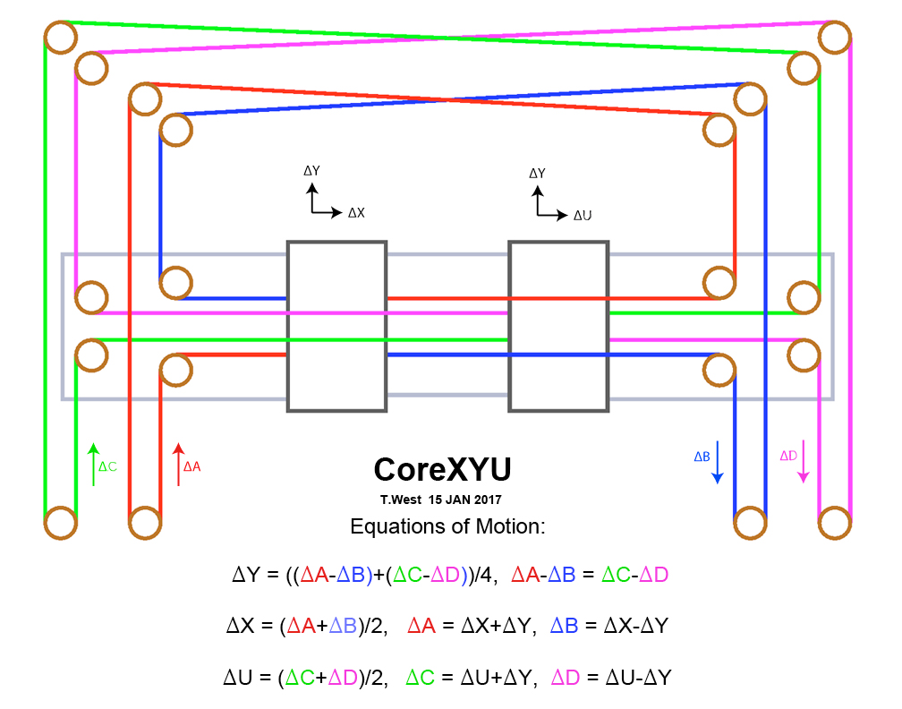
The corexy setup page is pretty confusing as well. M669 gcode explanation page is also confusing. It states this is the matrix, without explaining what the numbers in the matrix mean.
Sending M669 shows the kinematics in use. It shows the effect of an axis input on all axes. Axes are ordered X, Y, Z, U, V, W, A, B, C, D etc. This is the output if I set up a Duet to M669 K5:
M669 K5
ok
M669
Kinematics is CoreXYU, matrix:
1.00 1.00 0 0 0
1.00 -1.00 0 1.00 -1.00
0 0 1.00 0 0
0 0 0 1.00 1.00
0 0 0 0 1.00
ok
Read the matrix as:
output > X (A in diagram) Y (B in diagram) Z U (C in diagram) V (D in diagram) X input move 1.00 1.00 0 0 0 Y input move 1.00 -1.00 0 1.00 -1.00 Z input move 0 0 1.00 0 0 U input move 0 0 0 1.00 1.00 V input move (not used apart from homing) 0 0 0 0 1.00 ie a G1 Y1 move would move the X and U axes motors +1, Y and V axes motors -1.
If you think this is useful, I can add it to the description in M669.
ONE more issue maybe you can help with. If a tool has been activated, G28 will refuse to run saying that
Warning: the height map was loaded when the current Z=0 datum was not determined probing. This may result in a height offset.It means that a height map has been loaded before the Z axis has been homed. It's best to home the Z axis first, then load the height map. Probably you have a G29 S1 in your config.g or tool change macros.
sometimes when I run G30 (using a capacitive distance sensor) it refuses to run, but the bed slowly rises until it runs out of travel.
Not sure why this would be. Can you be more specific about in what circumstances it doesn't work?
Ian
Bed-slinger - Mini5+ WiFi/1LC | RRP Fisher v1 - D2 WiFi | Polargraph - D2 WiFi | TronXY X5S - 6HC/Roto | CNC router - 6HC | Tractus3D T1250 - D2 Eth
-
@droftarts said in Corexyuv vs corexy idex:
uld be. Can y
Like most things, it often takes longer to define the problem than to actually fix it. Yes, I think it would be a good idea to add more info to the M563 M669 and M584 page. Also, add how the V axis is added to the M584 command. You do need to be able to map the U and V axis to the U carriage for this kinematic to work. I finally got it to work with adding the U to the Y axis. This was after a LOT of guess work, and finally getting the X axis to work without the Y, then guessing and YAY it works....lol...When I figure out why my G30 command is giving this funky action (bed rising slowly beyond all limits with no carriage movements), I'll post it again. Thanks for all your help. I hope that I'm able to help with the overall movement toward better documentation etc. BTW, if I can be of any other assistance in writing, let me know...I know I've spent enough time with it now....lol....
-
@randyl00123 OK, here it is. I run G28 to home all, and I USED to have my find_Z_range macro called from the end of homeall.g, but after homeall.g, even if I manually call the macro find_Z_range.g, it doesn't move to bed center, but the bed starts rising slowly til it binds or causes other issues. Here are the error messages:
2022-02-04, 5:38:39 p.m. Emergency stop, attemping to reconnect...
2022-02-04, 5:38:24 p.m. M98 P"0:/macros/Find_Z_Range.g"
Error: G1/G2/G3: intermediate position outside machine limits
2022-02-04, 5:38:05 p.m. G28
Warning: the height map was loaded when the current Z=0 datum was not determined probing. This may result in a height offset.homeall.g
M117 S"about to run home Z"
;T-1 ;deselect all toolsM98 P"homez.g"
M117 S"back from home Z"M400
M117 S"about to run home y"
M98 P"homey.g"
M117 S"back from home y"M400 ;Wait for current moves to finish
M117 S"about to run home x"
M98 P"homex.g"M400
M117 S"about to run home U"
M98 P"homeU.g"
M117 S"back from home U"M400
;M98 P/macros/Find_Z_Range.g ;run find z range macro
M400 ;wait for movement to stop
G29 S1 ; load heightmapFind_Z_Range.g
;Find_Z_Range_Min-Max.g;T0 P0 ;select tool with X carriage but don't run the macro files associated
M117 S"about to run Find_Z_range"
M140 S80 ;heat the bed to 80C
;G31 X-38.32 Y-16.15 Z1.00 ;Z probe trigger sensitivity, offset in relation to nozzle. And trigger height adjustment
;decrease this number to lower the nozzle closer to the bed
;M117 S"T0";T0 ;select and prepare X hotend
M400 ;wait til everything stops
M117 S"move to bed center"
G1 X155.3 Y93.0 Z5 f4500 ;move to bed center for probing
M400 ;wait til everything stops
M117 S"probing"
G30 ;probe and set to zero
M117 S"reset Z max"
G1 H3 Z300 ;find z max and set it as M_max
G1 H3 Y300 ;rehome y gantry
G1 H3 X-300 ;rehome x carriage
M117 S"saving config_override"
M500 P10:31 ;save offsets etc to config-override.g
M117 S"exiting Find_Z_range"
homez.g
; homez.g
; called to home the Z axisG91 ; relative positioning
G1 H1 Z500 F1000 ; move Z down until the each motor endstop is triggered
G1 Z-5 F500 ; back off five mm
G1 H4 Z50 F200 ; move slowly back down to zstop switches and set this position as Z maxima that is declared in config.g
;G1 Z-10 ;move the bed up because with the T1 offsets, it confuses the max z fot T1
G90 ; absolute positioning;H1 means terminate move when endstop is hit.
;H2 individual motor mode either xy or z.
;H3 Terminate the move when endstop triggered and set the axis limit to the current position, orverriding the valuse set in M208.
;H4 - terminate the move when the endstop switch is triggered and update the current position (supported in RRF 3.2-b4 or newer)config.g (since I know you're gonna ask...lol)
; Configuration file for Duet WiFi (firmware version 3)
; executed by the firmware on start-up
;
; Randy's corexy idex 26 January 2022;General preferences
M111 S1 ; Debugging
G21 ; Work in millimetres
G90 ; send absolute coordinates...
M83 ; ...but relative extruder moves
M555 P0 ; Set firmware compatibility to look like RepRap_Firmware to look like rrf
M404 N1.75 D0.6 ; Set nominal filament diameter to 1.75 and nozzle width to 0.4
M575 P0 B250000 ; Set baud rate for USB port for Octoprint
M575 P1 S1 B57600 ; enable support for PanelDue (Default B57600);Network
M550 P"Randy corexy idex" ; set printer name
M552 S1 ; enable network
M586 P0 S1 ; enable HTTP
M586 P1 S1 ; enable FTP
M586 P2 S0 ; disable Telnet
M575 P1 B57600 S1 ; Set auxiliary serial port baud rate and require checksum (for PanelDue);Drives
M569 P7 S0 ;Drive 9(XX7)
M569 P8 S0 ;Drive 1(XY8)M569 P0 S0 ;Drive 8(UX) change to a 1 for forwards
M569 P9 S1 ;Drive 7(UY)M569 P2 S0 ;Drive 2(ZRR5) Right front lead screw driver 2
M569 P5 S0 ;Drive 5(ZCF2) Center rear lead screw driver 5
M569 P6 S0 ;Drive 6(ZRL6)Left front lead screw, driver 6M569 P3 S1 ;Drive 3(e0)
M569 P4 S1 ;Drive 4(e1);stepper drive configuration
M584 X8 Y7 Z2:5:6 U9 V1 E3:4 P4 ;this one works! X8 and Y7 are corexy X carriage. u9 (UX),v0 (UY) are the U carriage 2=ZRR5, 5=ZCF2,6=ZRL6;lead screws
M671 X300:120:-90 Y315:-60:315 F10 ;lead screws are located at drive 2 = back right corner, drive 5 at front center, drive 6 at left rearM669 K5 ; select 5=corexyu 8=CoreXYUV mode
;Axis Limits
M208 S0 X331 Y208 U451.00 Z268.35 ;set axis maxima S0 means maxima V350 - V240
M208 S1 X-98 Y0 U0 Z-2.00 ;set axis minima S1 means minima V80;endstops
M574 X1 S1 P"e0stop"
M574 U2 S1 P"xstop"
M574 Y2 S1 P"ystop" ;Y MAX active high endstop switchM574 Z2 S1 P"e1stop+zstop+duex.e2stop" ; configure active-high endstops for high end on Z - bed lowers to the three switches for initial self leveling
;M574 E0 S1 ;x filament sensor
;M574 E1 S1 ;U filament sensor;Heaters
M140 H0 ; map heated bed to heater 0
M308 S0 P"bedtemp" Y"thermistor" T100000 B4138 ; configure sensor 0 as thermistor on pin bedtemp
M950 H0 C"bedheat" T0 ; create bed heater output on bedheat and map it to sensor 0
M143 H0 S120 A2 ; set temperature limit for heater 0 to 120C
M307 H0 B0 R0.616 C164.1 D1.24 S1.00 V24.1 ;bed tuning settings
M570 S120 ;after a heater has been switched on, wait 120 seconds for it to get to the set temperature. If it takes longer, raise a heater fault.M308 S1 P"e0temp" Y"thermistor" T100000 B4138 ; configure sensor 1 as thermistor on pin e0temp
M950 H1 C"e0heat" T1 ; create nozzle heater output on e0heat and map it to sensor 1
M307 H1 B0 S1.00 ; disable bang-bang mode for heater and set PWM limit
M143 H1 S275 A2 ; set temperature limit for heater 1 to 280CM308 S2 P"e1temp" Y"thermistor" T100000 B4138 ; configure sensor 2 as thermistor on pin e1temp
M950 H2 C"e1heat" T2 ; create nozzle heater output on e1heat and map it to sensor 2
M307 H2 B0 S1.00 ; disable bang-bang mode for heater and set PWM limit
M143 H2 S275 A2 ; set temperature limit for heater 2 to 280C;M305 P2 X101 ;Use thermocouple for heater P2// note for when I upgrade to a K type thermocouple
;show the MCU and stepper driver temperature, send the following commands:
M308 S10 Y"mcu-temp" A"MCU"
M308 S11 Y"drivers" A"Steppers";Tools
;T0 (X carriage)
M563 P0 S"X" D0 H1 F2 ; X0 Y1Fan0 is thermostatically controlled, F2 is gcode controlled by tool P0
G10 L1 P0 X0 Y0 Z0 ;X has no offsets
M568 P0 R240 S250 ;set standby temperature at 240 and active temperature at 250
M307 H1 B0 R2.572 C150.0 D7.50 S1.00 V24.0 ;X hotend tuning parameters
M950 F0 C"duex.FAN4" ;create fan 0 on pin duex.FAN4 because fan0 on duet is always on
M106 P0 T75 S255 H1 ;when heater 1(XHotend) reaches 75 Celcius, turn on Fan0 at 100% (0-255)
M950 F2 C"FAN2" ;H1 x part fan;capacitive sensor
M558 P5 C"!zprobe.in" H10 F100 T2000 A3 S-1 ;enable pullup resistor(^), invert input (!), (H)Dive height 10mm,
;probing feed rate100mm/min
;travel speed between probe points 2000mm/min, A2 -probe each point twice
;M558 P9 means BLTouch P10 is stall detect. C" " is the pin input name, H5 means drop 5mm between points,
;A3 means probe three times S-1 means average the three probe distances
G31 X-38.32 Y-16.15 Z1.00 ;initial offsets to the center of the zprobe from X nozzle, redefined in find_Z_range.g which is called from homeall.gT1 (U carriage)
M563 P1 S"U" F3 D1 H2 X3 Y1:4 ;Fan1 is thermostatically controlled, F3 is gcode controlled by tool P1 X mapped to U axis, Y mapped to Y axiswhere X=0, Y=1, Z=2, U=3 etc, not by driver number
G10 L1 P1 X0.0 y1.5 Z-2.15 ;use U_find_the_dot to tweak
M568 P1 R240 S250 ;initial tool set and stanby temperatures
M307 H2 B0 R3.174 C186.4:172.2 D8.41 S0.50 V24.0 ;u hotend tuing parameters
M950 F1 C"FAN1" ;create fan 1 on pin fan1
M106 P1 T75 S255 H2 ;when heater 2(UHotend) reaches 75 Celcius, turn on Fan1 at 100%
M950 F3 C"duex.FAN3" ;H2 u part fan;T2 (Copy mode)
;M563 P2 S"copy" D0:1 H1:2 X0:3 Y1:4 F2:3 ; define tool 2
;G10 P2 X50 Y0 U-50 S0 R0 ; set tool offsets and temperatures
;M567 P2 E1:1 ; set mix ratio 100% on both extruders
;M568 P2 S1 ; turn on mixing for tool 2;T3 (Mirror mode)
;M563 P2 S"Mirror" D0:1 H1:2 X0:3 Y1:4 F2:3 ; define tool 3
;G10 P2 X50 Y0 U-50 S0 R0 ; set tool offsets and temperatures
;M567 P2 E1:1 ; set mix ratio 100% on both extruders
;M568 P2 S1 ; turn on mixing for tool 2;chamber
M308 S3 P"duex.e2temp" Y"thermistor" T100000 B4138 ; configure sensor 3 as thermistor on pin duex.e2temp
M950 H3 C"duex.e2heat" T3 ; create chamber heater output on duex.e2heat and map it to sensor 3
M307 H3 B1 S1.00 ; enable bang-bang mode for the chamber heater and set PWM limit
M141 H3 ; map chamber to heater 3
M143 H3 S100 ; set temperature limit for heater 3 to 100C;machine
M92 X80 Y80 U80 V80 Z1600 ; set axis steps per mm
M92 E428.46:428.46 ; set extruder steps per mm
M350 X16 Y16 U16 V16 Z16 E16:16 I1 ; configure microstepping with interpolation
M566 X1200 Y1200 U1200 V1200 Z12 E120:120 ; set maximum instantaneous speed changes (mm/min)
M203 X16000 Y16000 U16000 V16000 Z800 E1200:1200 ; set maximum speeds (mm/min)
M201 X600 Y600 U600 V600 Z500 E250:250 ; set accelerations (mm/s^2)
M906 X1100 Y1100 U1100 V1100 Z800 E800:800 I20 ; set motor currents (mA) and motor idle factor in per cent
M84 S30 ; Set idle timeout
M204 P666 T666 ; set print and travel accel
M566 P0 ; uses jerk between all moves. yes or no.;Print settings
;M207 S1.0 F3600 Z0.2 ; Retraction
;M572 D0:1 S0.05 ; Pressure advance
; M593 F60 ; Dynamic acceleration
; M592 D0 A0.03 B0.01 ; Non linear advance
; M592 D1 A0.06 B0.03 ; Non linear advance;CPU temp calibration
M912 P0 S-11;Automatic power saving
;M911 S22 R23 P"M913 X0 Y0 U800 G91 M83 G1 Z3 E-1 F1000" ; Set voltage thresholds and actions to run on power loss;Miscellaneous
;M911 S10 R11 P"M913 X0 Y0 G91 M83 G1 Z3 E-5 F1000" ; set voltage thresholds and actions to run on power lossM501 ;load settings from /sys/config.override.g