The tower motors ..... H E L P
-
@phaedrux said in The tower motors ..... H E L P:
drivers might work if segmentation is enabled
So how do I activate segmentation if M669 is not to be used on Delta?
-
 undefined tecno referenced this topic
-
@tecno use M665 to set delta kinematics and the delta parameters first. Then use M669 with just S and T parameters (no K parameter) to enable segmentation.
-
@dc42
; General preferences
M575 P1 S0 B57600 ; enable support for PanelDue
G90 ; send absolute coordinates...
M83 ; ...but relative extruder moves
M550 P"BigDelta" ; set printer name
M665 R300 L615 B275 H570 ; Set delta radius, diagonal rod length, printable radius and homed height
M666 X0 Y0 Z0 ; put your endstop adjustments here, or let auto calibration find them
M669 S1 T1 ; kinematics linear delta
M564 H0 S0 ; allow axis movement not homedStill nothing
-
@tecno Do your drivers/motors work at all? What happens if you simply set them up using standard cartesian kinematics, can you move them then?
-
What lines to change?
-
@tecno As I asked above, have you ever had your motors/drivers working with your current control board at all?
-
This post is deleted! -
Mini5 eth + 3pcs 1XD to DM556, so not with that configuration.
-
@arnold_r_clark
Can be done but the motors need high current so the Mini is not up to the task
-
@tecno said in The tower motors ..... H E L P:
@dc42
Missed G91But still no movement
It could mean that the enable polarity is wrong. Some questions:
- How did you wire the external drivers to the 1XD boards?
- Before you power up the drivers and the Duet, do the tower carriages move freely?
- After you power up and before you send any commands, do the carriages move freely or are they locked?
- After you command a motor using a G91 G1 H2 command, does the carriage move freely or is it locked?
-
@dc42
https://docs.duet3d.com/duet_boards/duet_3_can_expansion/duet_3_1xd_v1.0_wiring_03.pngYes
Same as above
Same as above -

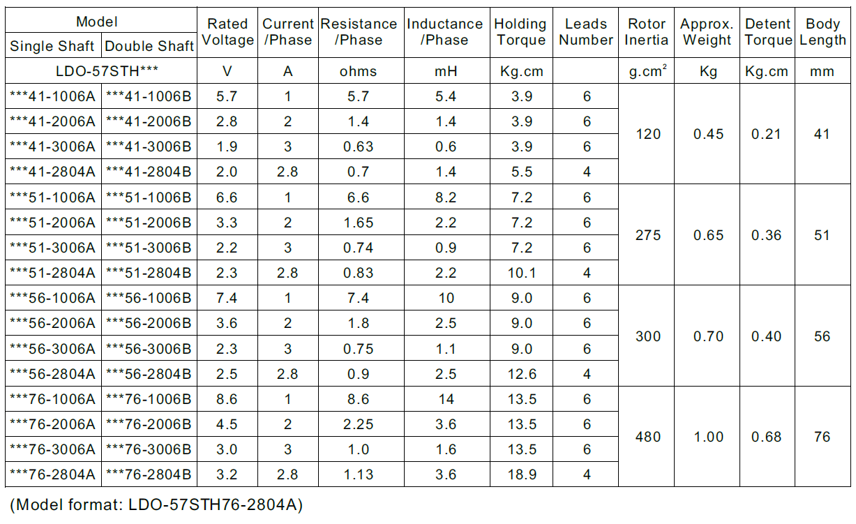
My motors are the last listed -2804
-
@tecno said in The tower motors ..... H E L P:
@dc42
https://docs.duet3d.com/duet_boards/duet_3_can_expansion/duet_3_1xd_v1.0_wiring_03.pngYes
Same as above
Same as aboveThanks. Your wiring link suggests that you have connected the Enable inputs of the drivers to the 1XD boards. So if you have set the Enable polarity correctly, the carriages should move freely before you command them to move, and after that (or when you use M17) they should lock. The fact that they are not locking suggests one of the following:
- Power is not being supplied to your external drivers
- Motor is not connected correctly to external driver
- Configuration of external driver incorrect
- Configuration of RRF is incorrect, so that it is not commanding the 1XD boards to move the motors
Please run the following command and report any error messages that you see:
M98 P"config.g"
-
36V
Connected as per docs
?
2022-06-03 18:54:47 M98 P"config.g"
HTTP is enabled on port 80
FTP is enabled on port 21
TELNET is enabled on port 23
Error: Setting not available for external drivers
Setting not available for external drivers
Setting not available for external drivers -
; Configuration file for Duet 3 Mini 5+ (firmware version 3.3)
; executed by the firmware on start-up
;
; generated by RepRapFirmware Configuration Tool v3.3.10 on Tue May 31 2022 17:03:35 GMT+0200 (centraleuropeisk sommartid); General preferences
M575 P1 S0 B57600 ; enable support for PanelDue
G90 ; send absolute coordinates...
M83 ; ...but relative extruder moves
M550 P"BigDelta" ; set printer name
M665 R300 L615 B275 H570 ; Set delta radius, diagonal rod length, printable radius and homed height
M666 X0 Y0 Z0 ; put your endstop adjustments here, or let auto calibration find them
M669 S1 T1 ; kinematics linear delta
M564 H0 S0 ; allow axis movement not homed; Wait a moment for the CAN expansion boards to start
G4 S2; Network
M551 P"bengt" ; set password
M552 P192.168.1.124 S1 ; enable network and acquire dynamic address via DHCP
M586 P0 S1 ; enable HTTP
M586 P1 S1 ; enable FTP
M586 P2 S1 ; enable Telnet; Drives
M569 P40.0 S1 R1 T10:10:10:10 ; physical drive 121.0 goes forwards
M569 P41.0 S1 R1 T10:10:10:10 ; physical drive 122.0 goes forwards
M569 P42.0 S1 R1 T10:10:10:10 ; physical drive 123.0 goes forwards
M569 P0.0 S1 ; physical drive 0.0 goes forwards
M584 X40.0 Y41.0 Z42.0 E0.0 ; set drive mapping
M350 E16 I1 ; configure microstepping with interpolation X16 Y16 Z16
M92 X80.00 Y80.00 Z80.00 E663.00 ; set steps per mm
M566 X1200.00 Y1200.00 Z1200.00 E1200.00 ; set maximum instantaneous speed changes (mm/min)
M203 X18000.00 Y18000.00 Z18000.00 E1200.00 ; set maximum speeds (mm/min)
M201 X1000.00 Y1000.00 Z1000.00 E1000.00 ; set accelerations (mm/s^2)
M906 X1000 Y1000 Z1000 E800 I30 ; set motor currents (mA) and motor idle factor in per cent
M84 S30 ; Set idle timeout; Axis Limits
M208 Z0 S1 ; set minimum Z; Endstops
M574 X2 S1 P"40.io1.in" ; configure switch-type (e.g. microswitch) endstop for high end on X via pin io0.in
M574 Y2 S1 P"41.io1.in" ; configure switch-type (e.g. microswitch) endstop for high end on Y via pin io1.in
M574 Z2 S1 P"42.io1.in" ; configure switch-type (e.g. microswitch) endstop for high end on Z via pin io2.in; Z-Probe
M558 P5 R0.4 C"io3.in+io4.out" H5 F1200 T6000 ; set Z probe type to effector and the dive height + speeds
G31 P500 X0 Y0 Z2.5 ; set Z probe trigger value, offset and trigger height
M557 R85 S20 ; define mesh grid; Heaters
M308 S0 P"temp0" Y"thermistor" T100000 B4138 ; configure sensor 0 as thermistor on pin temp0
M950 H0 C"out0" T0 ; create bed heater output on out0 and map it to sensor 0
M307 H0 B1 S1.00 ; enable bang-bang mode for the bed heater and set PWM limit
M140 H0 ; map heated bed to heater 0
M143 H0 S120 ; set temperature limit for heater 0 to 120C
M308 S1 P"temp1" Y"thermistor" T100000 B4138 ; configure sensor 1 as thermistor on pin temp1
M950 H1 C"out1" T1 ; create nozzle heater output on out1 and map it to sensor 1
M307 H1 B0 S1.00 ; disable bang-bang mode for heater and set PWM limit
M143 H1 S280 ; set temperature limit for heater 1 to 280C; Fans
M950 F0 C"out5" Q500 ; create fan 0 on pin out3 and set its frequency
M106 P0 S0 H-1 ; set fan 0 value. Thermostatic control is turned off
M950 F1 C"out4" Q500 ; create fan 1 on pin out4 and set its frequency
M106 P1 S1 H1 T45 ; set fan 1 value. Thermostatic control is turned on; Tools
M563 P1 D0 H1 F0 ; define tool 1
G10 P1 X0 Y0 Z0 ; set tool 1 axis offsets
G10 P1 R0 S0 ; set initial tool 1 active and standby temperatures to 0C; Custom settings are not defined
; Miscellaneous
;M501 ; load saved parameters from non-volatile memory -
Have been trying to search the forum what this Setting not available for external drivers is caused but cannot not find anything.
M98 P"config.g"
HTTP is enabled on port 80
FTP is enabled on port 21
TELNET is enabled on port 23
Error: Setting not available for external drivers
Setting not available for external drivers
Setting not available for external drivers -
@tecno Have you tried removing X, Y and Z from your M906 command, you can't set the current for external drivers.
-
Now I did that = still no movement. Error in M98 gone
M98 P"config.g"
HTTP is enabled on port 80
FTP is enabled on port 21
TELNET is enabled on port 23 -
Drivers are set to 1/16step and 3.2A
M569 P40.0 S0 R1 T10:10:10:10
M569 P41.0 S0 R1 T10:10:10:10
M569 P42.0 S0 R1 T10:10:10:10 -
With my DMM I can measure DIR shifting 4.78V to 0 and see a small shift in Step of 0.048V and EN is 4.78V