New heated enclosure printer
-
@phaedrux YAT says access to COM3 is denied. The last time I used YAT was to set the 6HC up so the setting should be the same.
-
What LEDs are lit when power is applied, either through VIN or USB?
-
@phaedrux The proper LEDs from the recover guide are lit. I reinstalled the windows drivers and now have 'Duet3 Motion control Electronics (COM3)' listed in devmgr and can connect in YAT. A M115 gives me this response:
'FIRMWARE_NAME: RepRapFirmware for Duet 3 MB6HC FIRMWARE_VERSION: 3.4.0 ELECTRONICS: Duet 3 MB6HC v1.01 or later FIRMWARE_DATE: 2022-03-15 18:57:26
ok' -
@phaedrux OK, I was able to use the 'fallback procedure #1' from the recovery guide, copied the 3.4.1 files to the sd card, performed the update with yat, then did a M115 and received the confirmation with the updated firmware version. Still get nothing from the ethernet connection and DWC. No lights on the ethernet port and Windows says the cable is unplugged. Paneldue is still blank. One slow blinking LED between SD card and reset switch, then the group of 4 leds, green, red, orange, blue, are all solid lit.
-
Are the files on the SD card still intact?
It almost sounds like it's not reading the SD card, or config.g files.
Can you try sending some commands over YAT to see if you can bring up networking and the paneldue?
M552 S1 (or whatever you're using for networking)
M575 P1 B57600 S1 for the paneldue.
-
@phaedrux SD card is readable but the config.sys was empty. I copied the .old file to overwrite it. Reinserted the SD card, now have green LEDs on the network port but still can't connect to dwc. Am using fixed IP of 168.192.2.1 and confirmed using yat and a M552. I can ping it from a command prompt and get replies. Paneldue is still blank, even if i send a M575 P1 B57600 S1 and get an ok confirmation.
Chris
Cosentino Engineering -
@phaedrux OK, go tthe network working and can connecto via DWC and the fan modifications to the config.g are still there so hopefully the rest of the configuration is correct.
The paneldue is still blank. Config.g is:
; Configuration file for Duet 3 (firmware version 3.3)
; executed by the firmware on start-up
;
; generated by RepRapFirmware Configuration Tool v3.3.10 on Thu Apr 14 2022 23:29:28 GMT-0400 (Eastern Daylight Time); General preferences
M575 P1 S1 B57600 ; enable support for PanelDue
G90 ; send absolute coordinates...
M83 ; ...but relative extruder moves
M550 P"hyperprinter" ; set printer name
M669 K1 ; select CoreXY mode
M564 H0 ; allow moves before homing; Wait a moment for the CAN expansion boards to start
G4 S2; Network
M552 P192.168.2.1 S1 ; enable network and set IP address
M553 P255.255.255.0 ; set netmask
M554 P192.168.2.20 ; set gateway
M586 P0 S1 ; enable HTTP
M586 P1 S0 ; disable FTP
M586 P2 S0 ; disable Telnet; Drives
M569 P0.1 S0 ; physical drive 0.1 goes forwards
M569 P0.2 S0 ; physical drive 0.2 goes forwards
M569 P0.0 S1 ; physical drive 0.0 goes forwards
M569 P121.0 S1 ; physical drive 121.0 goes forwards
M584 X0.1 Y0.2 Z0.0 E121.0 ; set drive mapping
M350 X128 Y128 Z8 E16 I1 ; configure microstepping with interpolation
M92 X56.14 Y56.14 Z320.00 E837.00 ; set steps per mm
M566 X500.00 Y500.00 Z60.00 E120.00 ; set maximum instantaneous speed changes (mm/min)
M203 X50000.00 Y50000.00 Z1000.00 E1200.00 ; set maximum speeds (mm/min)
M201 X10000.00 Y10000.00 Z50.00 E3000.00 ; set accelerations (mm/s^2)
M906 X300 Y300 Z5900 E1500 I30 ; set motor currents (mA) and motor idle factor in per cent
M84 S20 ; Set idle timeout
M572 D0 S0.03; CLEARPATH STEPPER TIMING
M569 P1 R1 T2
M569 P2 R1 T2; Axis Limits
M208 X-300 Y-250 Z0 S1 ; set axis minima
M208 X300 Y250 Z950 S0 ; set axis maxima; Endstops
M574 X2 S1 P"121.io2.in" ; configure switch-type (e.g. microswitch) endstop for low end on X via pin 121.io2.in
M574 Y1 S1 P"io1.in" ; configure switch-type (e.g. microswitch) endstop for low end on Y via pin io1.in
M574 Z1 S2 ; configure Z-probe endstop for low end on Z; Z-Probe
M950 S0 C"121.io0.out" ; create servo pin 0 for BLTouch
M558 P9 C"121.io0.in" H5 F120 A1 T20000 ; set Z probe type to bltouch and the dive height + speeds
G31 P500 X-2.31 Y-13.53 Z2.91 ; set Z probe trigger value, offset and trigger height
M557 X-290:290 Y-240:224 S116 ; define mesh grid; Heaters
M308 S0 P"temp0" Y"pt1000" ; configure sensor 0 as PT1000 on pin temp0
M950 H0 C"out0" T0 ; create bed heater output on out0 and map it to sensor 0
; M307 H0 R0.379 K0.064:0.000 D4.11 E1.35 S1.00 B0 OLD FROM FIRST TUNING RUN
M307 H0 R0.158 K0.054:0.000 D37.27 E1.35 S1.00 B0 ; FROM SECOND TUNING RUN WITH BED MOUNTED SENSOR
M140 H0 ; map heated bed to heater 0
M143 H0 S120 ; set temperature limit for heater 0 to 120C
M308 S1 P"temp1" Y"thermistor" T1000 ; configure sensor 3 as two 500 ohm thermistors in series on pin temp1
M950 H1 C"out1" T1 ; create chamber heater output on out1 and map it to sensor 1
M307 H1 R0.292 K0.731:0.000 D3.86 E1.35 S1.00 B0 ; FROM FIRST TUNING RUN
M141 H1 ; map chamber to heater 1
M143 H1 S150 ; set temperature limit for heater 1 to 150C
M308 S2 P"121.temp0" Y"pt1000" ; configure sensor 2 as PT1000 on pin 121.temp0
M950 H2 C"121.out0" T2 ; create nozzle heater output on 121.out0 and map it to sensor 2
M307 H2 R1.544 K0.166:0.000 D6.33 E1.35 S1.00 B0 V23.1 ; FROM FIRST TUNING RUN
M143 H2 S320 ; set temperature limit for heater 2 to 320C; Fans
M950 F0 C"out4" Q500 ; create fan 0 on pin out4 and set its frequency
M106 P0 C"Chamber 1" S1 H-1 ; set fan 0 name and value. Thermostatic control is turned off
M950 F1 C"out5" Q500 ; create fan 1 on pin out5 and set its frequency
M106 P1 C"Chamber 2" S1 H-1 ; set fan 1 name and value. Thermostatic control is turned off
M950 F2 C"121.out2" Q500 ; create fan 2 on pin 121.out2 and set its frequency
M106 P2 C"XY Extruder" S1 H-1 ; set fan 2 name and value. Thermostatic control is turned off
M950 F3 C"out7" Q500 ; create fan 3 on pin out7 and set its frequency
M106 P3 C"Water Cooler" S1 H-1 ; set fan 3 name and value. Thermostatic control is turned offM950 F4 C"121.out1" Q500 ; create fan 4 on pin 121.out1 and set its frequency
M106 P4 C"Layer fan" S1 H-1 ; set fan 4 name and value. Thermostatic control is turned off; Tools
M563 P0 S"xyhead" D0 H2 F2 ; define tool 0
G10 P0 X0 Y0 Z0 ; set tool 0 axis offsets
G10 P0 R0 S0 ; set initial tool 0 active and standby temperatures to 0C; Custom settings
M950 D1 C"spi.cs0+spi.cs2" -
@Phaedrux Even though the paneldue is blank I can access the files on the sd card.
-
OK, updated the paneldue firmwware through dwc and now it all seems good again. Phew! Thanks for the help. I wonder what happened.
-
When you updated the firmware to 3.4.1 did you manually update the dwc files to match?
What firmware version was on there before?
I think you figured it out but sounds like version mismatches.
-
@phaedrux Oops, no, but I did not do anything after getting it working again, wlll do that now. Previous version was 3.4.0 for the 6hc and dwc.
-
What PanelDue firmware did you land on?
-
@phaedrux I updated the paneldue and the 1LC toolboard to be 3.4.1 so all the components were at the same level. Happily printing away again. Thanks!
-
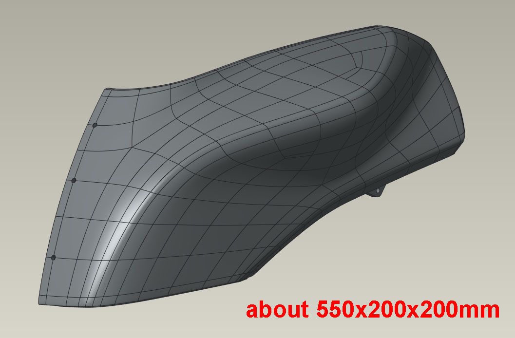
Oh yea! Finally after running this part about 20 times, here's a great final result. It is not the first white part, so was not a material swap fix.


It's just about as perfect a part as I can expect. The grooves on the backside are for 1/2" square steel tube for a small reinforcement frame that will be epoxied in and bolted inline with the two mounting holes so these parts will actually be used on the racetrack at up to 160mph.


The last few final changes were all thermal:
-added a layer fan, off for first 30% of build, then increasing to 75% at 75% of build.
-reduced the chamber temp as the build progressed, 50C to start, 45C midway, then 40C at 75%.
-increased minimum layer time from 10sec to 20 sec. Build time was 7hr2min.My take away from all this testing is that although it is often said to use minimal layer cooling on ABS, I suspect that this is for machines without a good thermal enclosure, which seems to make a big difference. I think that my air/temp mixing in the chamber is not that good, or the thermal gradient is just too big to keep constant with a thin bellows top with a gap for the printhead, or my sensor positions are reading low, or all of the above. With a 50C chamber setpoint, the bed sensor reads is 93 (set for 90) and the SSR never goes on. With a 45C chamber the bed is 92, with a 40C chamber, 91. So I am getting great heat retention to the point of excess, where the chamber heaters are heating the bed. Which really just means I have to figure out those numbers for this printer. Or maybe the heater tuning should be with all configurations of the various heaters on and off, but then it gets pretty complex and more likely to mess things up.
Once things get up to temp they are quite stable so I don't want to mess with it too much. So I’m getting there. Hopefully a revised layer fan will reduce the amount of heat soak, for lack a better term, and allow me to do 10sec layers instead of 20sec. Or I’ll just print two parts at a time. But for now, it is 235/90/50 to start, then dropping to 230/90/45 at the midpoint, then 220/90/40 for the end. Max speed on the big layers is 150mm/s, down to about 40mm/sec on the small layers.
Thanks again to all for the help!
-
Have a few good runs under my belt and am feeling pretty good about the settings. I revised the layer duct fan to blow a bit more and reduced the minimum layer time to 15 sec with no apparent change in the good results.
Still not quite sure I understand the thermal relationships going on. It takes setting the chamber temp to 35C for the bed heater to actually cycle. At 40C chamber or above it reads a couple of degrees over the setpoint of 90C, and continually reads 92 or 93.
@Phaedrux Is there some way to log or graph the activity of all the heater circuits to see what their duty cycles are? Maybe the good insulation and almost 80W of heat input from the printhead is enough to keep the chamber up to temp, as unlikely as that seems. At 50C chamber temp the outside surfaces are warm to the touch and the glass window pretty warm. At 35C chamber temp the outside surfaces or door window do not even feel warm.

The step in the airbox part is because it was being run with no supports even with completely horizontal overhangs to see how bad the bridging was. A blob developed at one overhang and hit the nozzle and shifted the bed a little but it kept printing. I only wanted the first couple of inches anyway to check the assembly, since that is where everything mounts to.

The marks on the back of the fairing parts are where I trimmed the ribs off but did not do a full finishing job. I'm very happy with the surface finish of the appearance surfaces. They have a consistent satiny appearance.
Now that I am feeling confident, one half of the gas tank/airbox cover is printing. Multiple smooth curvatures, some near vertical, some near horizontal. So far, so good. Projected to be a 13hr print and about halfway through. This is the first part with supports. I used the normal style as the tree support option resulted in a 2hr longer print time. Maybe I didn't tweak the settings optimally.
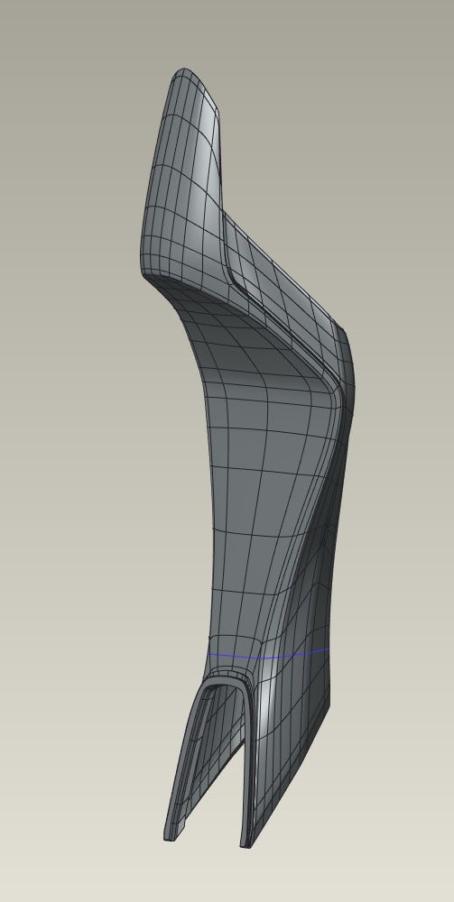
If that goes well, next I'll do the tailsection standing up, which is about 780mm tall, and really see how good the Z alignment, straightness, parallelism, etc are. I could print a large spiral vase box or cylinder and see quickly but that would be too easy!
Chris
Cosentino Engineering -
@coseng said in New heated enclosure printer:
Is there some way to log or graph the activity of all the heater circuits to see what their duty cycles are?
Not that I'm aware of.
-
@coseng said in New heated enclosure printer:
Is there some way to log or graph the activity of all the heater circuits to see what their duty cycles are?
No, but you can read the PWM averaged over the last 20 seconds or so from the object model.
Duet WiFi hardware designer and firmware engineer
Please do not ask me for Duet support via PM or email, use the forum
http://www.escher3d.com, https://miscsolutions.wordpress.com -
@dc42 OK, that is some info. How would I do that? Another option is to rig up an independent arduino logger. I guess if it is printing fine then no reason to fix it!
Chris
Cosentino Engineering -
Is there a fan in the enclosure to stir the air?
I assume the chamber heater is below the bed, so possibly having a stronger effect on the bed thermistor directly above it.
-
The tank finished successfully and is a mostly a really good print.


The only issues are on the horizontalish areas where I think another inner wall or skin layer is needed.


I was pleasantly surprised with how easily the standard supports broke off and the finish under them is still pretty good. I think a bottom skin is also needed. It is completely internal so does not really matter but it is nice to have 100% nice parts.

I then went tall and tried the subframe, but with minimal supports, which ended up being a mistake.

One out of two legs printed fine, so this could still be used as a mockup and i am letting it finish. On hindsight, I was suspicious of the small islands with nothing joining them to the main brim but decided to run it anyway. I'll add some supports before rerunning it.