I could use some help
-
@fcwilt I think I would, my friend, because I would be speeding and igniting all the stop light!
I just read your above post, the serious one, I’ll call it. Thank you!
-
@droftarts I should have written X, it was the printhead on the X-axis coming down.
-
; homex.g ; called to home the X axis ; ; generated by RepRapFirmware Configuration Tool v3.3.10 on Sun Jun 26 2022 17:21:53 GMT-0700 (Pacific Daylight Time) G91 ; relative positioning G1 H2 Z5 F3600 ; lift Z relative to current position G1 H1 X-225 F1800 ; move quickly to X axis endstop and stop there (first pass) G1 H2 X5 F3600 ; go back a few mm G1 H1 X-225 F360 ; move slowly to X axis endstop once more (second pass) G1 H2 Z-5 F3600 ; lower Z again G90 ; absolute positioning -
; Endstops M574 X1 S1 P"io5.in" ; configure switch-type (e.g. microswitch) endstop for low end on X via pin io5.in M574 Y1 S1 P"io6.in" ; configure switch-type (e.g. microswitch) endstop for low end on Y via pin io6.in M574 Z1 S1 P"io2.in" ; configure switch-type (e.g. microswitch) endstop for low end on Z via pin io2.in -
@fcwilt you know, I'm reading this code, and I'm thinking, that looks fine to me; there's nothing wrong with this code. And yet, the printer isn't doing any of this?
Mac
-
@fcwilt I think I need to reverse the y and z axis on the above two entries.
-
@mac said in I could use some help:
@fcwilt you know, I'm reading this code, and I'm thinking, that looks fine to me; there's nothing wrong with this code. And yet, the printer isn't doing any of this?
Mac
Well, the homing code for X does look correct but the video did not appear to show any motion along the X axis.
The two Z moves were clear.
Perhaps there was just the X5 move and I missed it.
That would happen if the endstop sensor was indicating active all the time, so the G1 H1 moves would never happen, just the little 5mm move.
Did you notice if that 5mm move happened?
Is the X axis endstop switch using the NO connection or the NC connection?
Frederick
Printers: a E3D MS/TC setup and a RatRig Hybrid. Using Duet 3 hardware running 3.4.6
-
@fcwilt the print head was ac100mm right of the endstop at least.
NO is normally open, NC is normally closed, I get that? Should I be looking at the white-green, 2-wire connectors plugged into I/O5 and I/06?
-
@fcwilt all of the endstops have a green wire and a white wire coming into them. All of the green wires are in the center. All of the white wires are under the red switch. All of the third poles on the switches are vacant. When something touches the switch, it makes the switch click. My assumption is that all of the switches are normally open. I’m also assuming that contacting an endstop closes it momentarily.
-
@fcwilt on the board, all of the white wires from the endstops are going to the #_in, and all of the green wires are going to gnd.
-
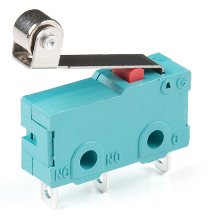
@mac There's no gurantee, but every microswitch I've ever used had common connection near the button-end of the switch and normally-open in the middle and normally-closed at the opposite end from the push button.
This would mean that you have your switch wired as normally-open.
From the M574 description, since you have a normally-open switch, you shold add the "!" character to your M574 lines:
For active low endstops, use type S1 and invert the input by prefixing the pin name with '!', for example M574 X1 S1 P"!xstop". Invert the input when using an NPN output inductive or capacitive sensor, or using a NO switch (not recommended, use a NC switch instead).
like this:
; Endstops
M574 X1 S1 P"!io5.in" ; configure switch-type (e.g. microswitch) endstop for low end on X via pin io5.in
M574 Y1 S1 P"!io6.in" ; configure switch-type (e.g. microswitch) endstop for low end on Y via pin io6.in
M574 Z1 S1 P"!io2.in" ; configure switch-type (e.g. microswitch) endstop for low end on Z via pin io2.in
I do not know what Duet board you are using, so I don't know if you need to enable pullups yet. Let me know what board you have and I'll reply.
I can also make a video showing how you can use the DWC Object Model plugin to see if your switches are configured the right-way by using a browser and pressing the switches.
SeemeCNC Rostock Max V3 converted to V3.2 with a Duet2 Ethernet Firmware 3.2 and SE300
-
@alankilian the switches came with the Xvico I’m putting a Duet3D Mini 5+ into.
So I agree, all of the endstops I’m using are normally open.
On the video, I would really like to see that.
Thanks for the input on the coding. RRF asked, is your endstop low or high? It didn’t ask, is it NO or NC,? So that’s a new bit of info worth having.
-
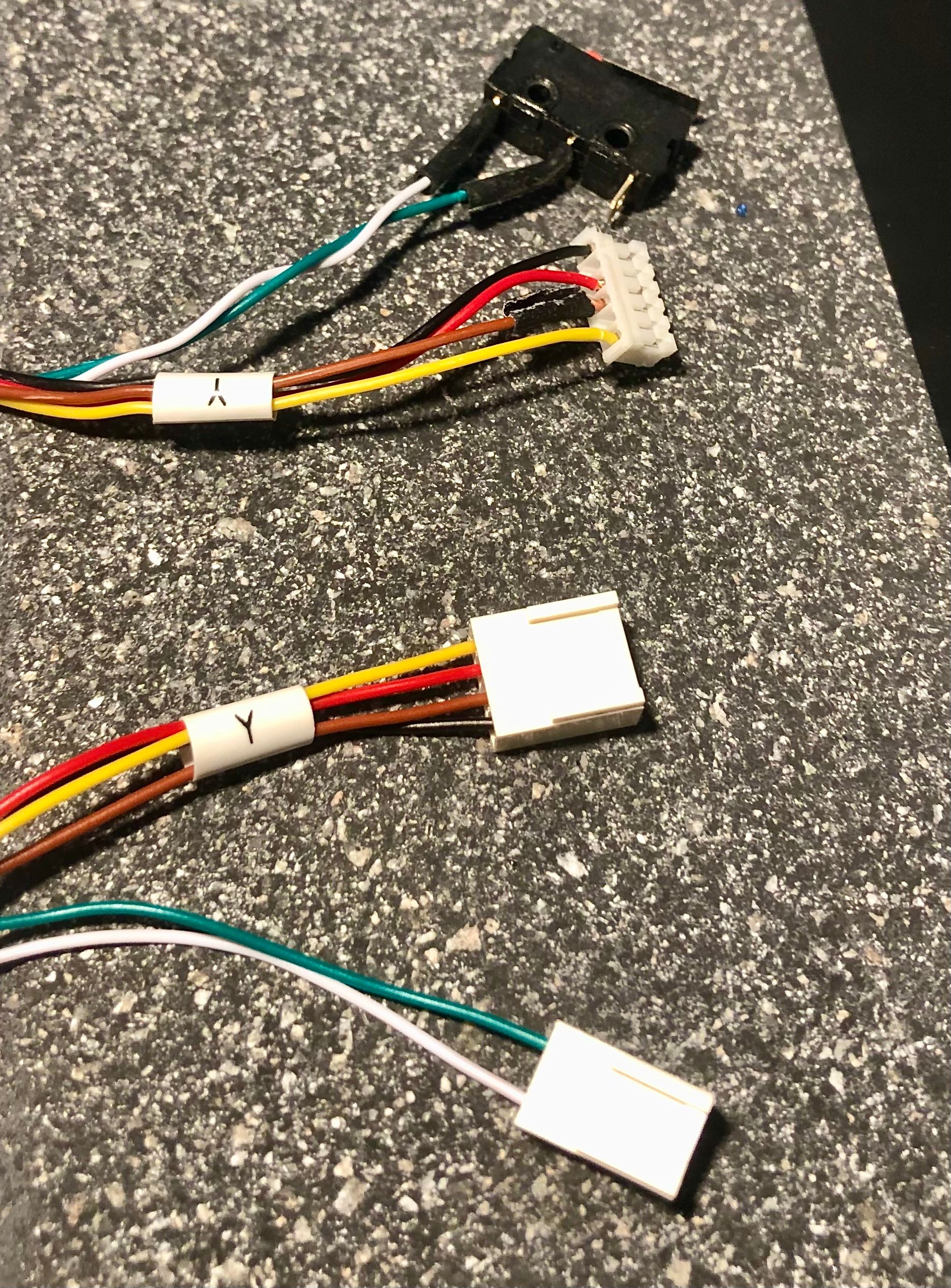
@alankilian that’s great that you found that picture of one of my wires.
-
@alankilian I’m wondering what you’re thinking, re: editing the endstops? The problem I think I’m having is the print-head isn’t getting to the endstops. Are you suggesting that the endstops are invisible because they are portrayed incorrectly? Honestly, if that’s true, that’s brilliant!
-
@mac said in I could use some help:
@alankilian I’m wondering what you’re thinking, re: editing the endstops? The problem I think I’m having is the print-head isn’t getting to the endstops. Are you suggesting that the endstops are invisible because they are portrayed incorrectly? Honestly, if that’s true, that’s brilliant!
No, not invisible at all, just the opposite, in a way.
If you are right that your endstop switches are NO then when they are not touched the board is seeing them as active.
So your X homing G1 H1 moves never happen because G1 H1 moves stop as soon the endstop is active.
For NO switch connections you need the ! character which makes NO connection appear inactive when the endstop switch is not touched.
A better solution is to re-wire the endstop switches to use the COM And NC connections.
Didn't I post a picture, at one point, of an endstop switch showing the three connections COM, NO and NC?
Here it is in case my memory is faulty.
Frederick
Printers: a E3D MS/TC setup and a RatRig Hybrid. Using Duet 3 hardware running 3.4.6
-
From the M574 description, since you have a normally-open switch, you shold add the "^" character to your M574 lines:
You wrote
^, but it should be!.Ian
Bed-slinger - Mini5+ WiFi/1LC | RRP Fisher v1 - D2 WiFi | Polargraph - D2 WiFi | TronXY X5S - 6HC/Roto | CNC router - 6HC | Tractus3D T1250 - D2 Eth
-
@droftarts this is the first time I’m seeing that picture, so, this is all new info to me. To be clear: my endstops should all be inverted? Yes, or no?
-
@droftarts @alankilian I do remember our discussion about rewiring the endstops to use the vacant post. I’ll have to find that comment.
-
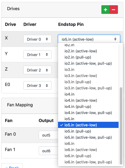
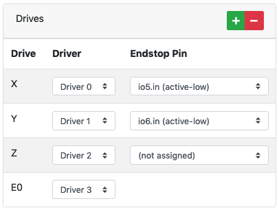
@mac I thought we resolved this in another of your threads? If you're using NO and C on the microswitch, ie NOT the outside two pins, then yes, you need to invert the endstop. In the configurtion tool, on the "I/O Mapping" page, select "io[x].in (active low)" on the drop down list for the endstops wired like this:
On the "Endstops" page, select Endstop type "Switch" and, because all your endstops are high end, "High end".
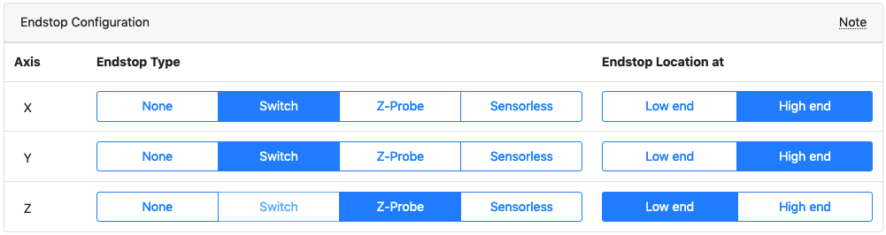
This should give the output:
; Endstops
M574 X2 S1 P"!io5.in"                        ; configure switch-type (e.g. microswitch) endstop for high end on X via pin !io5.in
M574 Y2 S1 P"!io6.in"                        ; configure switch-type (e.g. microswitch) endstop for high end on Y via pin !io6.in
M574 Z1 S2                                   ; configure Z-probe endstop for low end on Z

; Z-Probe
M950 S0 C"io3.out"                           ; create servo pin 0 for BLTouch
M558 P9 C"io3.in" H5 F120 T6000              ; set Z probe type to bltouch and the dive height + speeds
G31 P500 X0 Y0 Z2.5                          ; set Z probe trigger value, offset and trigger height
Your homing macros should also output from the configuration tool to suit this setup.
Ian
Bed-slinger - Mini5+ WiFi/1LC | RRP Fisher v1 - D2 WiFi | Polargraph - D2 WiFi | TronXY X5S - 6HC/Roto | CNC router - 6HC | Tractus3D T1250 - D2 Eth
-
@droftarts @alankilian Okay, COM is O on the switch pictured. So using the COM (O) and the NC posts, the white wire should go to the NC (Signal), and the green wire should go to the COM (O) (GND)? I’m trying to visualize the IO_5 (X), IO_6 (Y), and IO_2 (Z) connections on the board.