I could use some help
-
This post is deleted! -
@mac the ‘12V rating’ does not matter. Far more important is phase resistance and phase inductance.
Ian
-
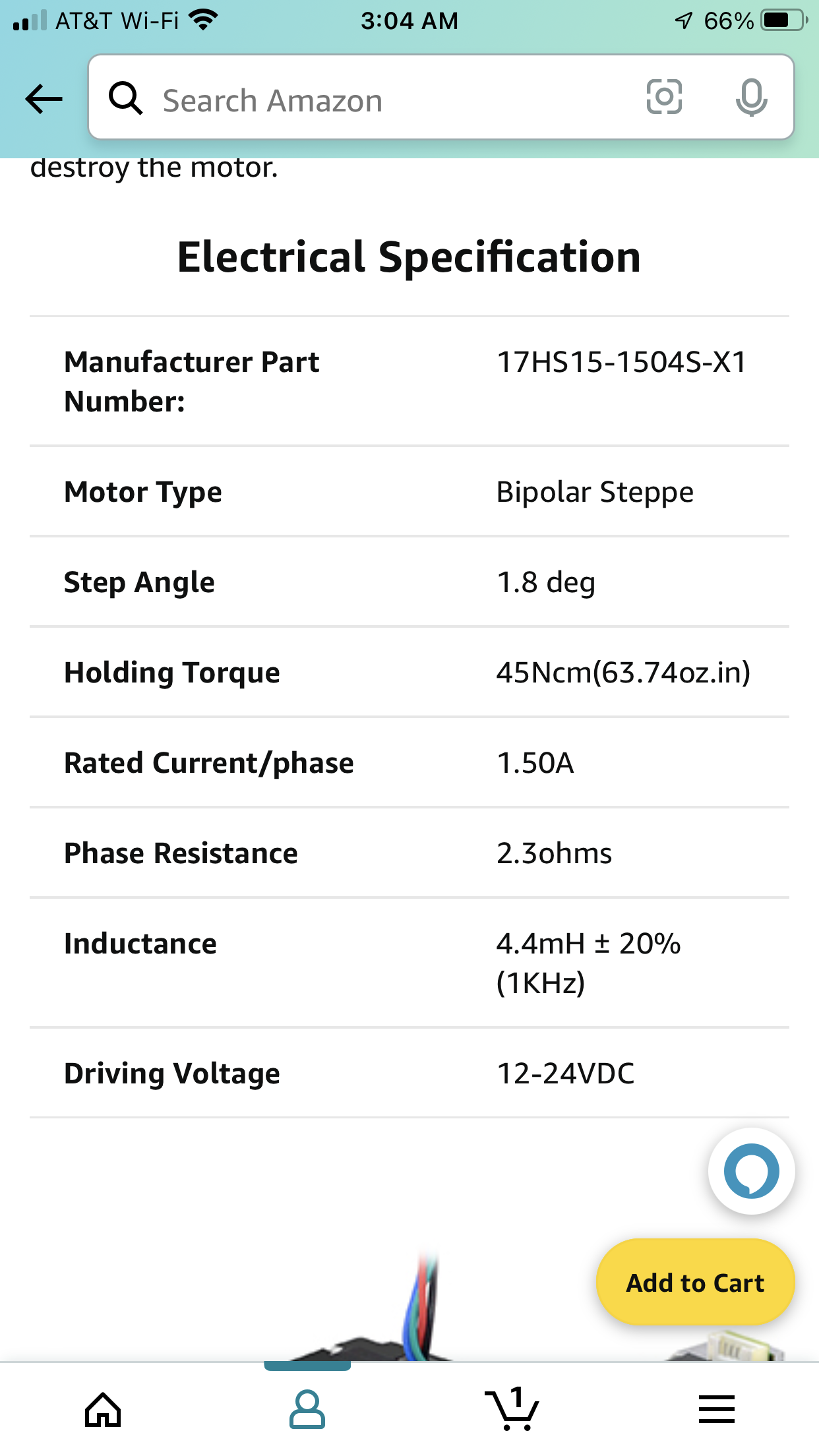
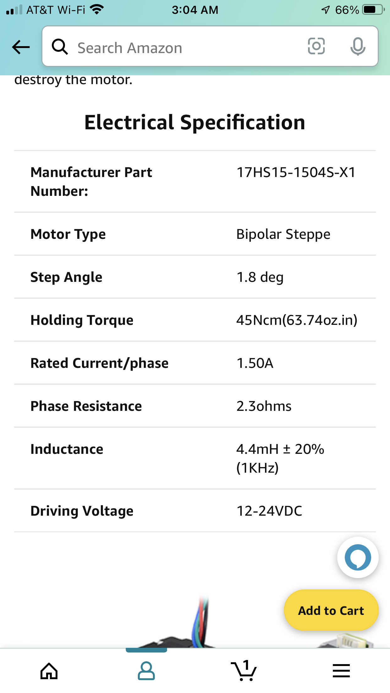
@droftarts here’s a picture of the motor info, please advise asap
-
@fcwilt heres the 12 volt motor info, please advise asap
-
@fcwilt so, I ended up getting the motors you suggested. The information is somewhat misleading. They are 12-24 volts, not 24 volts only. I should have them on the 6th.
-
@droftarts I purchased the motors Frederick suggested. They are 12-24 volts, not 24 volts only. I’ll have them on July 6.
-
@mac said in I could use some help:
@deckingman thanks for the input. Can you provide more info? If I have a 12 volt power supply, how do I provide for 4-24 volt motors?
Maybe this will help your understanding. A Watt is a unit of power. In electrical terms, Wattage is Voltage x Current. The stepper drivers use constant current but vary the voltage. To keep the maths simple, let's say you set the current to 1 amp. Now let's say for example that to move your carriage takes 3 Watts. If the current is 1 amp, then the voltage would need to be (3Watts/1Amp = ) 3 volts. But let's say you want to accelerate faster which needs more power and let's say that power is 6Watts. We still provide 1 Amps because that's how the stepper driver works, so to get 6Watts, the voltage would have to increase (in this case to 6/1 = 6V). But let's say you have a heavy hot end and want to accelerate it fast and that the power to do that would be 12 Watts. In that scenario, still keeping the current to 1 Amp, the voltage would need to be 12V. If you have a 12V power supply, that's the maximum you could go. But if you had a 24V power supply, still keeping the current at 1 Amp, you could get 24 Watts of power.
So, take no notice of what the (probably Chinese) manufacturer says about driving voltage - with constant current drivers as used by Duet, it's meaningless.
-
@deckingman Ah, the lovely world of E ='s I times R. So, the 24 volt powerful has no problem supplying a 12 volt system? And providing more than 12 volts when needed? Is that why the motors I purchased are rated as 12-24 volts? They're expecting to have as much as 24 volts available to them?
-
@mac said in I could use some help:
@deckingman ...............Is that why the motors I purchased are rated as 12-24 volts? They're expecting to have as much as 24 volts available to them?
Not really. If you read the description carefully, you''ll see that it says "Driving Voltage" - it isn't a rating as such so don't think of them as being rated at 12-24V. It's more likely a number (probably picked of thin air) which might be relevant for ancient drivers that don't use constant current. Some CNC users on these and other forums, use 48V and higher PSUs, but still the with same motors.
But, yes. The drivers will supply whatever voltage is required from almost bugger all, up to the maximum that the PSU can deliver. So 24V will always give you more headroom.
It's a similar thing with heater cartridges. A 60 Watt 24 V heater will draw 2.5 Amps but a 60 Watt 12V heater will draw 5 Amps.
-
@deckingman so the voltage isn't "there," but it's available.
-
@mac said in I could use some help:
@deckingman so the voltage isn't "there," but it's available.
Yes, pretty much - I just edited my previous post if you want to read it again.
-
@mac
Morning mac!
Hope you are feeling better.
So what motors did you end up ordering?
Frederick
-
@fcwilt I ordered the ones you suggested, and hopefully, they'll be here on July 6th.
Other than that, I've been taking things apart, removing sheathing from this and that, collecting wires that belong together, and wrapping them in spiral tubing. So off with the sheathing, and on with the spiral tubing!
-
-
@mac said in I could use some help:
@fcwilt I ordered the ones you suggested, and hopefully, they'll be here on July 6th.
Other than that, I've been taking things apart, removing sheathing from this and that, collecting wires that belong together, and wrapping them in spiral tubing. So off with the sheathing, and on with the spiral tubing!
Do you have the tools and skills to change the white wires on the endstop switches from the NO terminal to the NC terminal?
If you could that would be a good thing to do, as it reduces the possibility of noise being picked up by the endstop wiring.
Not essential but suggested.
Frederick
-
@fcwilt @droftarts @Nightowl @rexx @deckingman @alankilian We're going to take a few days off (to blow things up), and then we'll be back towards the 6th of July to start all over again.
We're tossing the questionable motors from the Xvico / Ender 3 clone (of a clone of a clone), and putting in some proper kit that will play nicely with the Duet3D Mini 5+ (hopefully). Me and the team, I should call them the A-Team, we're going to yak at each other a bit more. Who knows, can a thread on this forum reach a thousand comments?
Mark
-
@fcwilt your suggestions are essential, my friend. So tell me which wire goes where and I'll get right to it (on the switch, and on the connector?).
-
@mac said in I could use some help:
@fcwilt your suggestions are essential, my friend. So tell me which wire goes where and I'll get right to it (on the switch, and on the connector?).
Only on the micro-switches themselves.
Based on past discussions the white wires are connected to the switch terminals labeled NO.
IF, I repeat, IF that is the situation you would need to unsolder the wire from the NO terminal and solder it to the NC terminal.
Do that for each switch.
Once that is done the M574 statements for the endstops would need to have the ! character removed, which changes them from NO "mode" to NC "mode".
Frederick
-
spool 3d have LDO HT nema 17 they are your best bet or steppermotoronline
-
@rexx thanks Rex! Appreciate it.


