I could use some help
-
@mac
; Drives
M569 P0.0 D3 V0 S1                                       ; physical drive 0.0 goes forwards
M569 P0.1 D3 V0 S1                                       ; physical drive 0.1 goes forwards
M569 P0.2 D3 V0 S1                                       ; physical drive 0.2 goes forwards
M569 P0.3 D3 V0 S1                                       ; physical drive 0.3 goes forwards
The D3 V0 commands were suggested by Ian.
-
@mac Okay, TEST No. 1: M119 SEND.
Result: Endstops - X: not stopped, Y: not stopped, A: not stopped, Z probe: not stopped.
TEST No. 2: M119 SEND with each endstop depressed (one at a time).
Result: Endstops - X: at max stop, Y: not stopped, Z: not stopped, Z probe: not stopped.
Result: Endstop - X: not stopped, Y: at max stop, Z; not stopped, Z probe: not stopped.
Result: Endstops - X: not stopped, Y: not stopped, Z; at min stop, Z probe: not stopped.TEST No. 3: Execute M564 H0 S0 to jog each axis, are they going in the correct direction?
M564 H0 S0 executed.
Change to Dashboard.
All jog buttons are available.TEST X: I tried to jog right and left 10mm. Nothing happened.
TEST Y: I tried to jog Y-10. The bed shuddered in place.
TEST Z: I tried to jog Z-5 and Z+5. Z did not move.NOTE: I had to extend the X and Z endstops because I printed out a box for the board, and mounted it on the right Z rail. I don't know if this is possible, or not, but the wire I used to extend the endstops was slightly larger than the original wire.
There is also the possibility that the extensions are shorting out. I'll have to check that.
I'll also check the board to see if I made an error plugging the endstops in.
Given that the M119 tests worked, it seems like the endstops should be working?
RESULTS: X, Y, and Z failed to perform as expected.
TEST No. 4
G91 (sets relative movement, G1 H1 Y-10 F3600 what happens?
G1 H1 Y-10 F3600 SENT
RESULT: Bed shuddered in place.
At this point, I'm going to suspend the test.
Mac
-
@mac Here's my most recent config.g file.
; Configuration file for Duet 3 Mini 5+ (firmware version 3.3) ; executed by the firmware on start-up ; ; generated by RepRapFirmware Configuration Tool v3.3.10 on Sun Jul 03 2022 11:18:04 GMT-0700 (Pacific Daylight Time) ; General preferences G90 ; send absolute coordinates... M83 ; ...but relative extruder moves M550 P"Frankenstein's Cinderella" ; set printer name ; Network M552 S1 ; enable network M586 P0 S1 ; enable HTTP M586 P1 S0 ; disable FTP M586 P2 S0 ; disable Telnet ; Drives M569 P0.0 D3 V0 S1 ; physical drive 0.0 goes forwards M569 P0.1 D3 V0 S1 ; physical drive 0.1 goes forwards M569 P0.2 D3 V0 S1 ; physical drive 0.2 goes forwards M569 P0.3 D3 V0 S1 ; physical drive 0.3 goes forwards M584 X0.0 Y0.1 Z0.2 E0.3 ; set drive mapping M350 X16 Y16 Z16 E16 I1 ; configure microstepping with interpolation M92 X80.00 Y80.00 Z4000.00 E420.00 ; set steps per mm M566 X900.00 Y900.00 Z60.00 E120.00 ; set maximum instantaneous speed changes (mm/min) M203 X6000.00 Y6000.00 Z600.00 E1200.00 ; set maximum speeds (mm/min) M201 X500.00 Y500.00 Z200.00 E250.00 ; set accelerations (mm/s^2) M906 X1200 Y1200 Z1200 E1200 ; set motor currents (mA) M84 S0 ; Disable motor idle current reduction ; Axis Limits M208 X0 Y0 Z0 S1 ; set axis minima M208 X220 Y220 Z240 S0 ; set axis maxima ; Endstops M574 X2 S1 P"io5.in" ; configure switch-type (e.g. microswitch) endstop for high end on X via pin !^io5.in M574 Y2 S1 P"io6.in" ; configure switch-type (e.g. microswitch) endstop for high end on Y via pin !^io6.in M574 Z1 S1 P"io2.in" ; configure switch-type (e.g. microswitch) endstop for low end on Z via pin !^io2.in ; Z-Probe M950 S0 C"io3.out" ; create servo pin 0 for BLTouch M558 P9 C"io3.in" H5 F120 T3600 ; set Z probe type to bltouch and the dive height + speeds G31 P500 X15.875 Y0.625 Z2.5 ; set Z probe trigger value, offset and trigger height M557 X5:190 Y5:215 S10 ; define mesh grid ; Heaters M308 S0 P"temp0" Y"thermistor" T100000 B4092 ; configure sensor 0 as thermistor on pin temp0 M950 H0 C"out0" T0 ; create bed heater output on out0 and map it to sensor 0 M307 H0 B1 S1.00 ; enable bang-bang mode for the bed heater and set PWM limit M140 H0 ; map heated bed to heater 0 M143 H0 S33 ; set temperature limit for heater 0 to 33C M308 S1 P"temp1" Y"thermistor" T100000 B4092 ; configure sensor 1 as thermistor on pin temp1 M950 H1 C"out1" T1 ; create nozzle heater output on out1 and map it to sensor 1 M307 H1 B0 S1.00 ; disable bang-bang mode for heater and set PWM limit M143 H1 S100 ; set temperature limit for heater 1 to 100C ; Fans M950 F0 C"out3" Q500 ; create fan 0 on pin out3 and set its frequency M106 P0 S0 H-1 ; set fan 0 value. Thermostatic control is turned off M950 F1 C"out4" Q500 ; create fan 1 on pin out4 and set its frequency M106 P1 S1 H1 T45 ; set fan 1 value. Thermostatic control is turned on ; Tools M563 P0 S"optional" D0 H1 F0 ; define tool 0 G10 P0 X0 Y0 Z0 ; set tool 0 axis offsets G10 P0 R0 S0 ; set initial tool 0 active and standby temperatures to 0C ; Custom settings are not defined ; Miscellaneous M501 ; load saved parameters from non-volatile memory M911 S21 R23 P"M913 X0 Y0 G91 M83 G1 Z3 E-5 F1000" ; set voltage thresholds and actions to run on power loss -
@mac
; Endstops
M574 X1 S1 P"io5.in"                             ; configure switch-type (e.g. microswitch) endstop for high end on X via pin !^io5.in
M574 Y1 S1 P"io6.in"                             ; configure switch-type (e.g. microswitch) endstop for high end on Y via pin !^io6.in
M574 Z1 S1 P"io2.in"                             ; configure switch-type (e.g. microswitch) endstop for low end on Z via pin !^io2.in
They were X2 and Y2 in the newest config.g.
I had nothing (I know of) to do with that change. I did research this thread, found Ian's and FcWilt's messages, and changed them to the above, however.
Mac
-
@mac well, I was really hoping that X2, Y2 Z1 code was the problem. I was hoping even more that X1, Y1, Z1 would allow me to jog the bed back 10 mm. No Such Luck. It shuddered in place for a brief moment, and that was that.

-
@mac I've been working on this machine since 2 AM. Putting the new motors in, putting the board in a box, and wiring everything together, putting the bed back together after I reinforced the mounting plate.
All for nothing.
-
@deckingman @droftarts @fcwilt
Here’s something completely different:

That antenna’s from one of my spare quadcopters that isn’t legal to fly anymore. I put it on the Duet Mini 5+ to see if it would work, and / or improve reception. In my opinion it improved reception a lot!
Mac
-
@mac sorry this change hasn’t gone to plan. Did you check the phases on the new motors? Can you take a picture of one of the new motors, of the wiring coming out, and the wiring of the Duet?
Your config looks sensible. You rewired the endstops to NC?
Ian
Bed-slinger - Mini5+ WiFi/1LC | RRP Fisher v1 - D2 WiFi | Polargraph - D2 WiFi | TronXY X5S - 6HC/Roto | CNC router - 6HC | Tractus3D T1250 - D2 Eth
-
@droftarts Hey, Ian, good to hear from you. I'll take some pictures and answer your questions in the next post.
Mac
-
@droftarts okay, here’s what I know at the moment. Since the y-axis was shuddering, I decided to test it. Here’s a picture of my first test.
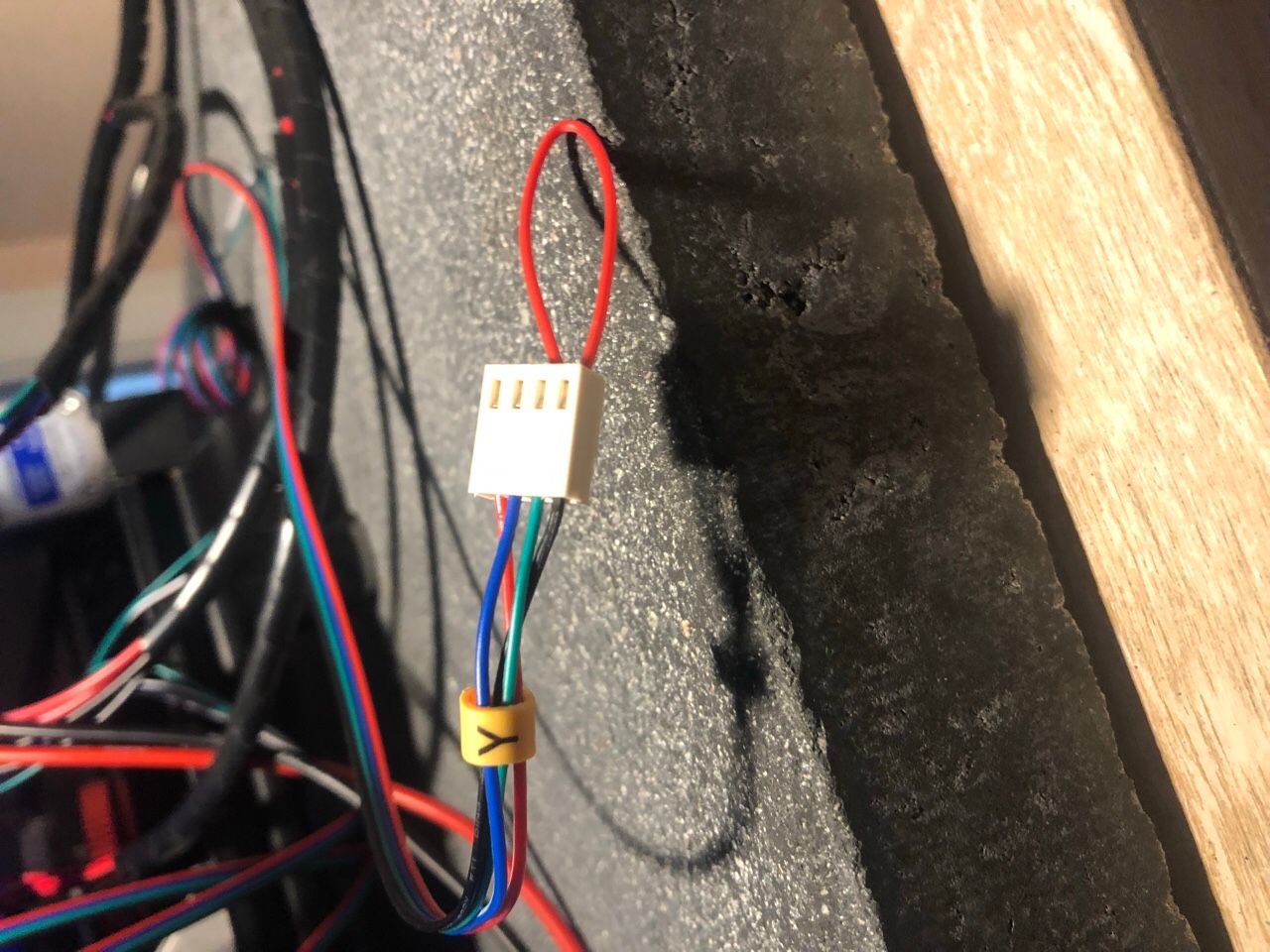
The wiring is black, green, blue, red. From the top of the board, which is where the wifi is, down. So that should be A+ (Black), A- (Green), B+ (Blue), B- (Red).
When I short black and green, the bed is very hard to move.
Here’s the thing that makes no sense! When I short blue and red, the bed is EASY to push back and forth.
According to the information that came with these motors, blue and red are B+ and B-!
I did not check the phases initially because I thought I had concrete written /printed info from the company I bought these motors from.
Here’s a picture of the wiring. REM: the board is upside down.
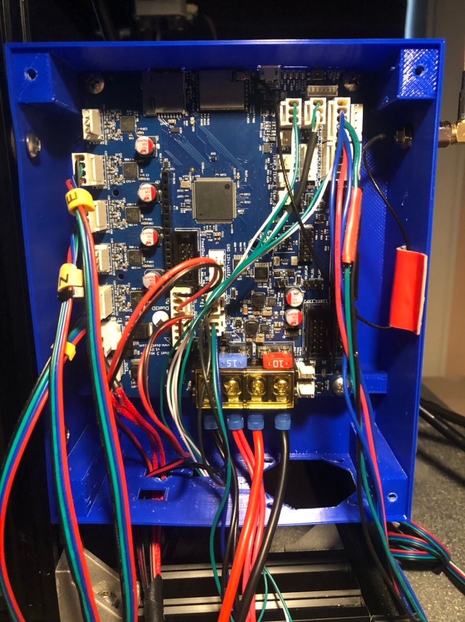
Mac
-
@mac
Hi Mark,
A few things I want to ask:
1st question:
When you made that video, when facing the printer, the X endstop was at the left end of the X axis and the Y endstop was at the back of the printer.
Has that changed?
If it has not changed those endstops are at the min end of X and Y but the M119 is reporting the max end for X and Y.
2nd question:
Do the steppers have a connector as opposed to the wires being a permanent part of the stepper?
3rd question:
If the steppers do have a connector did you check the continuity of the cable with the duet connectors attached?
Frederick
Printers: a small Utilmaker style, a small CoreXY and a E3D MS/TC setup. Various hotends. Using Duet 3 hardware running 3.4.6
-
@mac do you ever get any “phase disconnected” errors in DWC? Because it really sounds like the blue or red wire are not making the connection. That would explain the axis just shuddering, and no resistance when you short it.
Ian
Bed-slinger - Mini5+ WiFi/1LC | RRP Fisher v1 - D2 WiFi | Polargraph - D2 WiFi | TronXY X5S - 6HC/Roto | CNC router - 6HC | Tractus3D T1250 - D2 Eth
-
@droftarts @fcwilt the problem’s in the connectors I made. Out of three connectors tested, X, Y, and Z, Y shuddered, X and Z did nothing. That’s ten connectors out of twelve that are shite.
I’ve been working for 13 hours. Time to take a break.
Mac
-
@fcwilt the motors are fine, the cables that came with them are fine. I checked. It’s the connectors I installed. 10 out of 12 are shite.
Mac
-
@mac said in I could use some help:
@droftarts @fcwilt the problem’s in the connectors I made. Out of three connectors tested, X, Y, and Z, Y shuddered, X and Z did nothing. That’s ten connectors out of twelve that are shite.
I’ve been working for 13 hours. Time to take a break.
Mac
Hi Mac
Whenever you return to work perhaps you could find a way to make a video showing us how you are crimping those contacts onto the wire.
I've done hundreds of such crimps and I might mess up 1 out of 100.
Perhaps we can spot the problem you are having.
Frederick
Printers: a small Utilmaker style, a small CoreXY and a E3D MS/TC setup. Various hotends. Using Duet 3 hardware running 3.4.6
-
@fcwilt No, yes, no (sad face).
But we're over it, and we're at it again. I haven't eating in eight hours, so I'm going to have a cheese sandwich and then I'm turning in.
Maybe tomorrow we'll share some pictures of the Rat's Next that Frankenstein's Cinderella lives in.
Mac
-
@fcwilt If I had a camera I could hold in my mouth, I might do that.
I'll think about it.
-
@deckingman @droftarts @fcwilt
Just so you know, X is working correctly, Y is going backwards, and Z is going backwards (with a pronounced jerk).
All things I can take care of.
This is the first good news I've had since I bought this board.
Mac
-
-
@mac that’s great, nice and quiet too! Z problem looks like steps per mm, which I think you have set to 4000, so it is moving way more than 5mm, and so fast that it is skipping steps. Try 800, or possibly 400, which is more common for Z on these kinds of machines.
Ian
Bed-slinger - Mini5+ WiFi/1LC | RRP Fisher v1 - D2 WiFi | Polargraph - D2 WiFi | TronXY X5S - 6HC/Roto | CNC router - 6HC | Tractus3D T1250 - D2 Eth