I could use some help
-
@mac
; Endstops
M574 X1 S1 P"io5.in"                             ; configure switch-type (e.g. microswitch) endstop for high end on X via pin !^io5.in
M574 Y1 S1 P"io6.in"                             ; configure switch-type (e.g. microswitch) endstop for high end on Y via pin !^io6.in
M574 Z1 S1 P"io2.in"                             ; configure switch-type (e.g. microswitch) endstop for low end on Z via pin !^io2.in
They were X2 and Y2 in the newest config.g.
I had nothing (I know of) to do with that change. I did research this thread, found Ian's and FcWilt's messages, and changed them to the above, however.
Mac
-
@mac well, I was really hoping that X2, Y2 Z1 code was the problem. I was hoping even more that X1, Y1, Z1 would allow me to jog the bed back 10 mm. No Such Luck. It shuddered in place for a brief moment, and that was that.

-
@mac I've been working on this machine since 2 AM. Putting the new motors in, putting the board in a box, and wiring everything together, putting the bed back together after I reinforced the mounting plate.
All for nothing.
-
@deckingman @droftarts @fcwilt
Here’s something completely different:

That antenna’s from one of my spare quadcopters that isn’t legal to fly anymore. I put it on the Duet Mini 5+ to see if it would work, and / or improve reception. In my opinion it improved reception a lot!
Mac
-
@mac sorry this change hasn’t gone to plan. Did you check the phases on the new motors? Can you take a picture of one of the new motors, of the wiring coming out, and the wiring of the Duet?
Your config looks sensible. You rewired the endstops to NC?
Ian
-
@droftarts Hey, Ian, good to hear from you. I'll take some pictures and answer your questions in the next post.
Mac
-
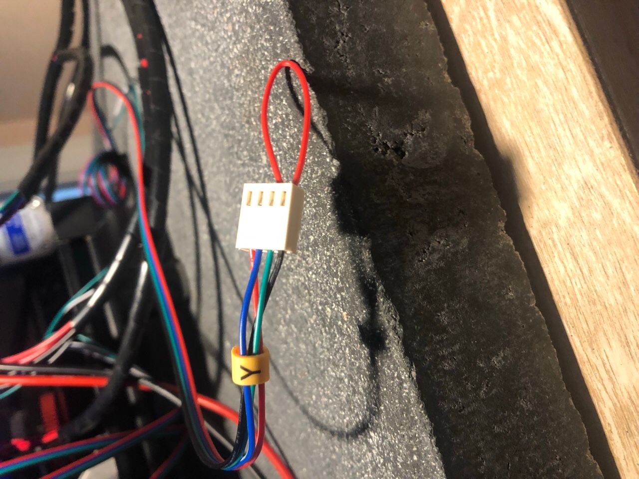
@droftarts okay, here’s what I know at the moment. Since the y-axis was shuddering, I decided to test it. Here’s a picture of my first test.

The wiring is black, green, blue, red. From the top of the board, which is where the wifi is, down. So that should be A+ (Black), A- (Green), B+ (Blue), B- (Red).
When I short black and green, the bed is very hard to move.
Here’s the thing that makes no sense! When I short blue and red, the bed is EASY to push back and forth.
According to the information that came with these motors, blue and red are B+ and B-!
I did not check the phases initially because I thought I had concrete written /printed info from the company I bought these motors from.
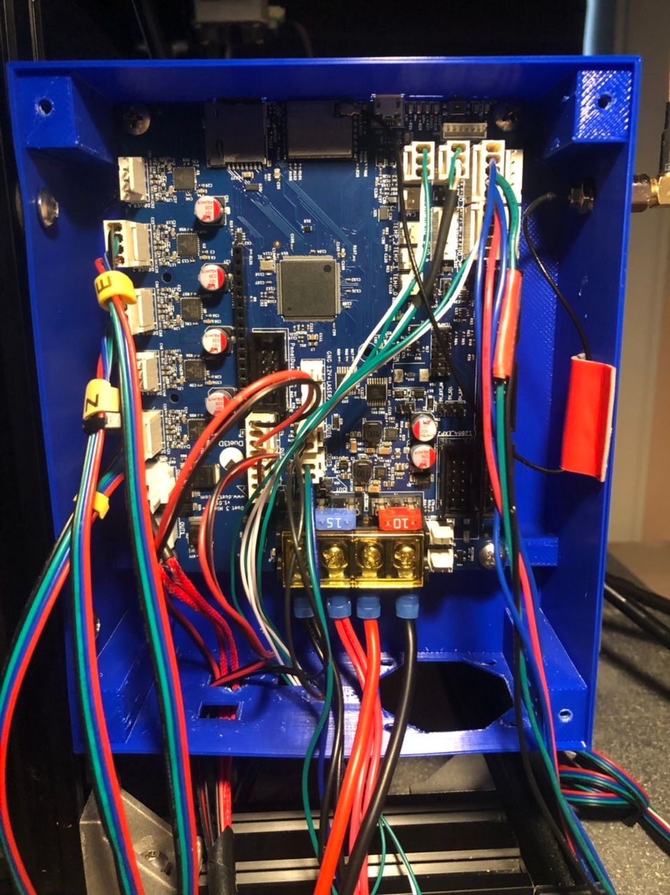
Here’s a picture of the wiring. REM: the board is upside down.

Mac
-
@mac
Hi Mark,
A few things I want to ask:
1st question:
When you made that video, when facing the printer, the X endstop was at the left end of the X axis and the Y endstop was at the back of the printer.
Has that changed?
If it has not changed those endstops are at the min end of X and Y but the M119 is reporting the max end for X and Y.
2nd question:
Do the steppers have a connector as opposed to the wires being a permanent part of the stepper?
3rd question:
If the steppers do have a connector did you check the continuity of the cable with the duet connectors attached?
Frederick
-
@mac do you ever get any “phase disconnected” errors in DWC? Because it really sounds like the blue or red wire are not making the connection. That would explain the axis just shuddering, and no resistance when you short it.
Ian
-
@droftarts @fcwilt the problem’s in the connectors I made. Out of three connectors tested, X, Y, and Z, Y shuddered, X and Z did nothing. That’s ten connectors out of twelve that are shite.
I’ve been working for 13 hours. Time to take a break.
Mac
-
@fcwilt the motors are fine, the cables that came with them are fine. I checked. It’s the connectors I installed. 10 out of 12 are shite.
Mac
-
@mac said in I could use some help:
@droftarts @fcwilt the problem’s in the connectors I made. Out of three connectors tested, X, Y, and Z, Y shuddered, X and Z did nothing. That’s ten connectors out of twelve that are shite.
I’ve been working for 13 hours. Time to take a break.
Mac
Hi Mac
Whenever you return to work perhaps you could find a way to make a video showing us how you are crimping those contacts onto the wire.
I've done hundreds of such crimps and I might mess up 1 out of 100.
Perhaps we can spot the problem you are having.
Frederick
-
@fcwilt No, yes, no (sad face).
But we're over it, and we're at it again. I haven't eating in eight hours, so I'm going to have a cheese sandwich and then I'm turning in.
Maybe tomorrow we'll share some pictures of the Rat's Next that Frankenstein's Cinderella lives in.
Mac
-
@fcwilt If I had a camera I could hold in my mouth, I might do that.
I'll think about it.
-
@deckingman @droftarts @fcwilt
Just so you know, X is working correctly, Y is going backwards, and Z is going backwards (with a pronounced jerk).
All things I can take care of.
This is the first good news I've had since I bought this board.
Mac
-
-
@mac that’s great, nice and quiet too! Z problem looks like steps per mm, which I think you have set to 4000, so it is moving way more than 5mm, and so fast that it is skipping steps. Try 800, or possibly 400, which is more common for Z on these kinds of machines.
Ian
-
@droftarts will do, thanks,Ian.
-
@fcwilt I’ve never changed where any of the endstops are mounted. If I understand, in RRF, the X and Y endstops should be classified as “LOW”, not HIGH?”, correct?
And if I change those High to Low classifications, M119 will report that when the are depressed, they will be at Min, not Max?
RRF should change their Low and High to Min and Max, or, change their Min and Max to Low and High. The way RRF is now is creating confusion with how DWC reports the functions of endstops (min and max).
Mac
-
@fcwilt that is a very good idea, and I am going to make that video today. Thanks, Frederick!
Mac