Input Shaping makes no difference whatsoever
-
Hello Everyone,
I have build a huge printer with a heavy print head (about 8 kilos), which works really well but one of the only last remaining issue I have with it is a bit of ringing.
Nothing really crazy, the parts still look pretty good and are 100% functional, but it is visible and I'd like to get rid of if in order to crank up the speeds a little bit.I've installed an accelerometer, as per recommendation, (LIS3DH). I've wired it and made the data acquisition in order to get an accelerometer profile with all the X Y and Z graphs. So far, so good. I'm using RRF v3.4.1.
But then, I decided to print a test cube while trying to adjust the input shaping on the fly, in order to see what difference it makes.
During the print, I tried to change everything: the frequency, the rebound, the different input shaping algorythms, etc. Well nothing made any difference whatsoever. The cube ringing artifacts remain the same all over the cube, it looks like it's been done without input shaping at all.I'm wondering, did I do anything wrong? Anyone having any idea?
Thanks in advance for your help! -
Here is a test print showing very well the defects (a bit too well actually, it looks absolutely horrific on the pictures but it's okay/acceptable IRL
 )
)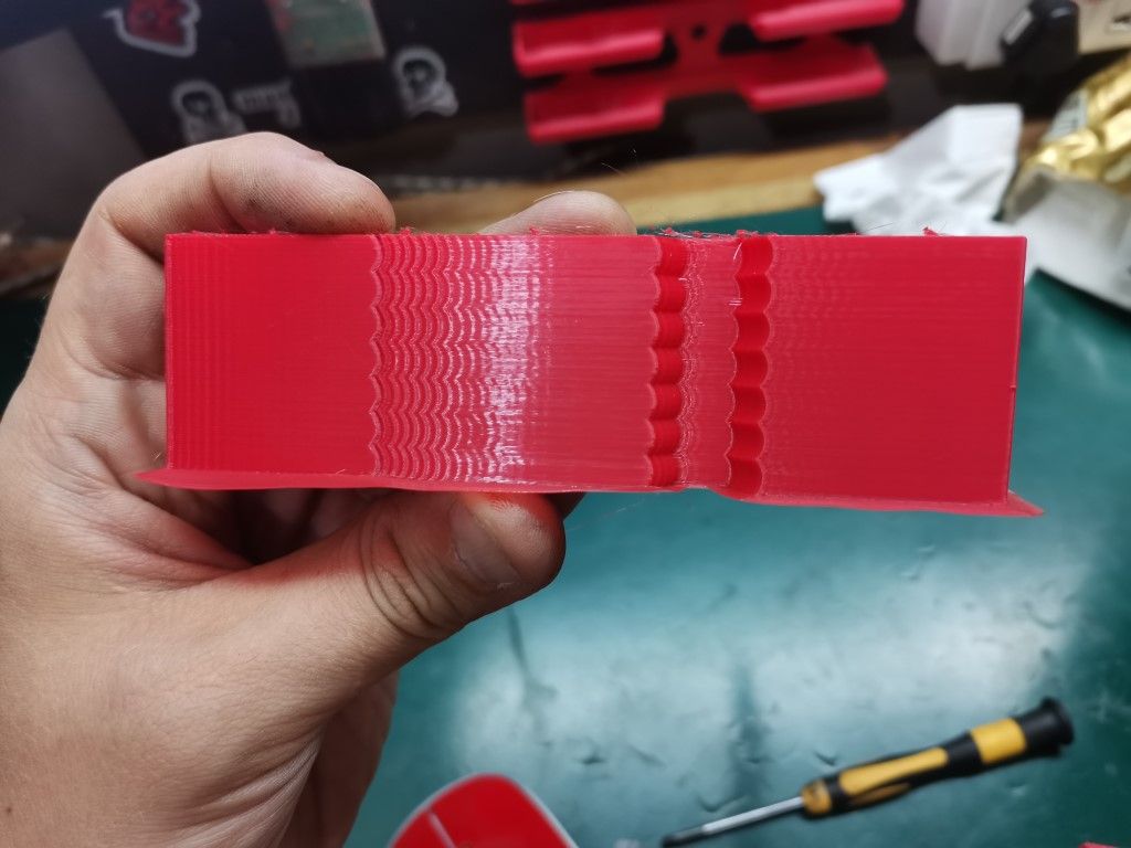
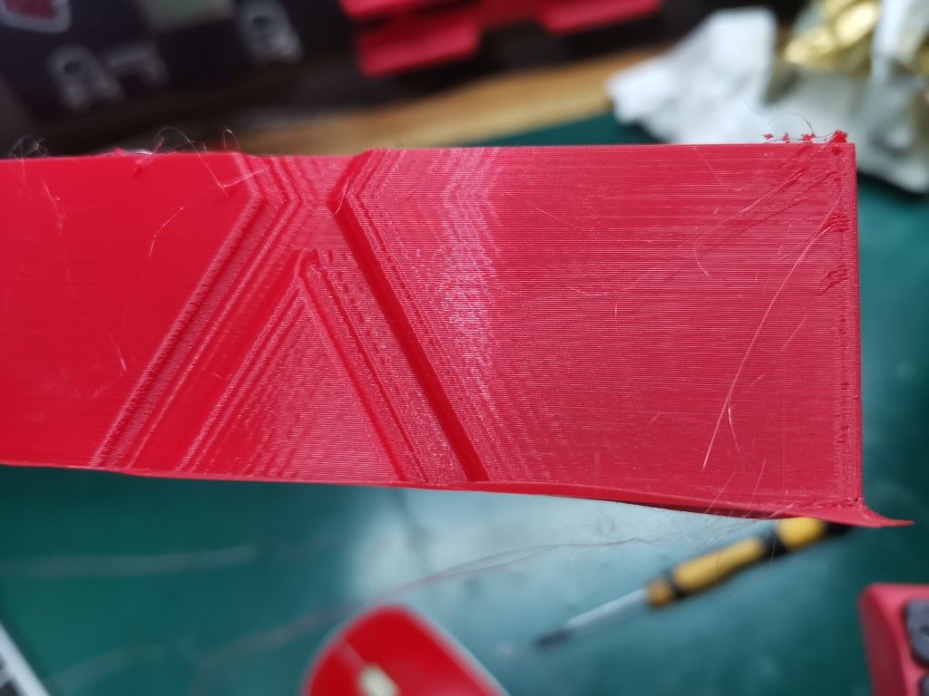
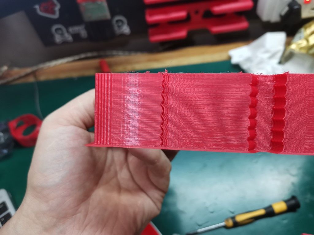
I can't spot the layer at which I turned the input shaping on, or back off, and this for any of the input shapers I tried (tried them all each one after the other). Every layer look pretty much exactly the same to me.
That's puzzling, I don't expect it to make miracles of course, but I was expecting at least some visible change, for better or worse.
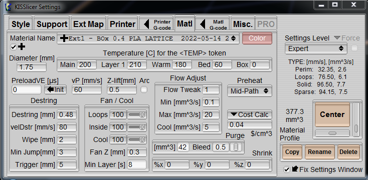
Here is what I thought was a valid setup, but as you just saw on the print pictures it didn't really make a difference:
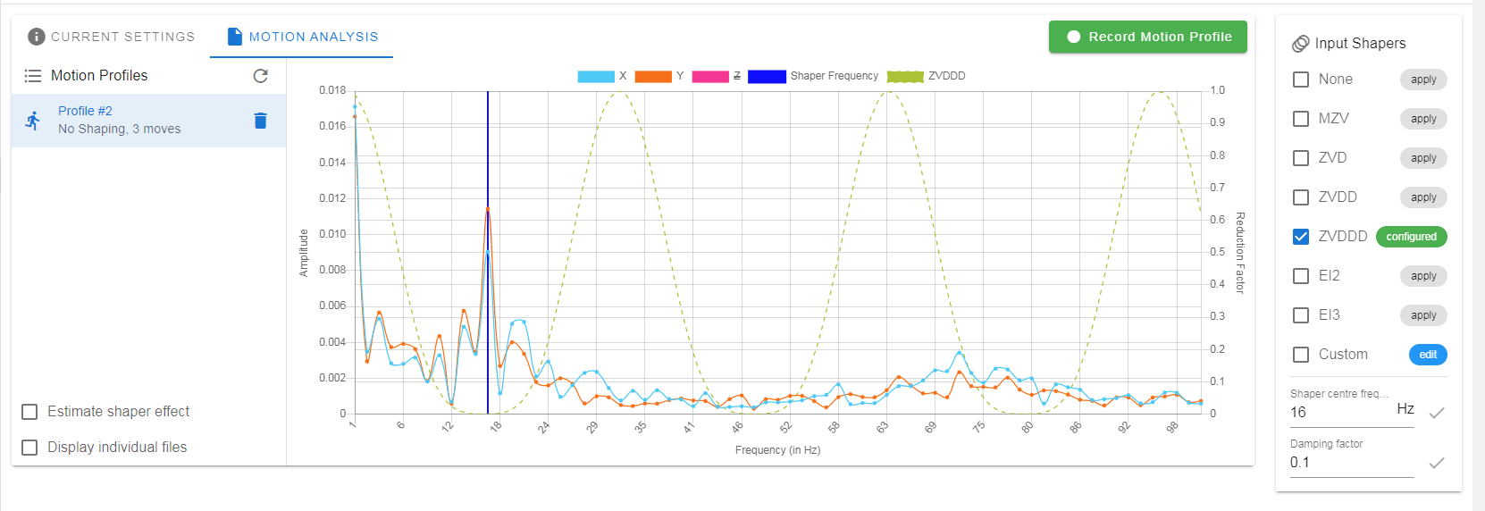
I tried different center frequencies, I tried to lower the damping to lower values, tried all the input shapers obvioulsy and also created other profiles, did many motion recordings too. I'm kinda stuck and I don't know where to look...Any idea/suggestion what could be going on there?
-
@mrdui please post your firmware version (M122), config.g, and the actual input shaping commands you sent.
Ian
Bed-slinger - Mini5+ WiFi/1LC | RRP Fisher v1 - D2 WiFi | Polargraph - D2 WiFi | TronXY X5S - 6HC/Roto | CNC router - 6HC | Tractus3D T1250 - D2 Eth
-
@droftarts said in Input Shaping makes no difference whatsoever:
@mrdui please post your firmware version (M122), config.g, and the actual input shaping commands you sent.
Ian
Sure, I will post it this evening when I get access to the printer
")
I haven't sent any command (except the ones set up in config.g), I'm not sure what command should I send ?
Do you mean that if I click on "Apply" next to the selected input shaper it doesn't send the command to apply this shaper configuration and use it and I actually have to send it manually? That would explain why it wouldn't work, but that would be strange, what would be the purpose of the "Apply" button then? -
@mrdui do you have mesh bed compensation enabled, or move segmentation enabled? It has come to light that move segmentation interferes with input shaping, where the segment length or mesh spacing interval is too short to contain the acceleration or deceleration part of the move.
Duet WiFi hardware designer and firmware engineer
Please do not ask me for Duet support via PM or email, use the forum
http://www.escher3d.com, https://miscsolutions.wordpress.com -
@dc42 first, let me thank you for everything you're doing, I'm a huge fan of your work and very admirative of the incredible knowledge at both hardware and software you have. Bravo.
I indeed use mesh bed compensation, so there might be something there. Is there any workaround? I really need the bed compensation on this machine because its size makes it difficult to find a mirror flat enough to get consistent good first layers on the whole surface.
Ah also here is my config.g file for you @droftarts :
; Prusa i3 config file for dc42 Duet firmware

; Prologue and  comms section
M111 S0                             ; Debug off
M552 S1;
M550 P"BOx Giant Printer"				        ; Machine name (can be anything you like)
M551 *****                        ; Machine password
;*** If you have more than one Duet on your network, they must all have different MAC addresses, so change the last digits
M540 P0xBE:0xEF:0xDE:0xAD:0xFE:0xAE ; MAC Address
;*** Adjust the IP address and gateway in the following 2 lines to suit your network
M552 P192.168.1.122						; IP address (0 = use DHCP)
M554 P192.168.1.1                   ; Gateway
M553 P255.255.255.0                 ; Netmask
M555 P2                             ; Set output to look like Marlin
M575 P1 B57600 S1					; Comms parameters for PanelDue
G90; Absolut coordianates
M83; Relative extruder coordinates

M955 P0 C"spi.cs4+spi.cs3" ;Accelerometer config

; fans
M950 F0 C"fan0" Q50                           ; create fan 0 on pin fan0 and set its frequency
M106 P0 S1 H1 T65 X80                                  ; set fan 0 value. Thermostatic control is turned on

M950 F1 C"fan1" Q50                          ; create fan 1 on pin fan1 and set its frequency
M106 P1 S0 H-1                            ; set fan 1 value. Thermostatic control is turned off


M584 X0 Y1 Z2:3:4 E8; three Z motors connected to driver outputs
M671 X-40:940:450 Y247:247:740 S10 ; leadscrews at left (connected to Z) and right (connected to E1) of X axis and maximum correction
M208 X20:700 Y350:350 ; X carriage moves from -5 to 205, Y bed goes from 0 to 200

; Movement section
M569 P0 S0                          ; Drive 0 goes forwards (change to S0 to reverse it)
M569 P1 S1                          ; Drive 1 goes forwards
M569 P2 S1                          ; Drive 2 goes forwards
M569 P3 S0                          ; Drive 3 goes forwards
M569 P4 S0                          ; Drive 4 goes forwards
M569 P5 S1                          ; Drive 4 goes forwards
M569 P6 S0                          ; Drive 4 goes forwards
M569 P7 S0                          ; Drive 4 goes forwards
M569 P8 S1                          ; Drive 4 goes forwards

; Endstops
;old code M574 X2 Y2 Z2 S1					; set endstop configuration (X and Y endstops only, at low end, active high)
M574 X2 S1 P"xstop"                            ; configure switch-type (e.g. microswitch) endstop for high end on X via pin xstop
M574 Y2 S1 P"ystop"                            ; configure switch-type (e.g. microswitch) endstop for high end on Y via pin ystop
M574 Z2 S1 P"zstop"                            ; configure switch-type (e.g. microswitch) endstop for high end on Z via pin zstop

;Filament Endstop
; old code M591 D0 P1 C3 S1; filament monitor connected to E0 endstop
M591 P1 C"e0stop" S1 D0 ; filament monitor connected to E0 endstop


M350 X16 Y16 Z16 E16 I1;

M906 X2000 Y2000 Z2400 E1200 I45           ; Set motor currents (mA)
M201 X800 Y800 Z300 E1200            ; Accelerations (mm/s^2)
M203 X15000 Y15000 Z900 E2100       ; Maximum speeds (mm/min)
M566 X800 Y800 Z20 E600              ; Minimum speeds mm/minute
M208 X715 Y715 Z600					; set axis maxima (adjust to suit your machine)
M208 X0 Y0 Z0 S1					; set axis minimum (adjust to make X=0 and Y=0 the edge of the bed)
M92 X100 Y100 Z1600	; Set axis steps/mm
M92 E415                      	; Set extruder steps per mm
G21                                 ; Work in millimetres
G90                                 ; Send absolute coordinates...
M83                                 ; ...but relative extruder moves

; Z probe section
M950 S0 C"exp.heater7" ; create servo/gpio 0 on heater 3 pin on expansion connector
M558 P9 C"^zprobe.in" H2.5 F220 T16000  ; BLTouch connected to Z probe IN pin

; Squareness adjustment:
M556 S80 X-0.625 Y0.5 Z0.5

; old code M307 H7 A-1 C-1 D-1;  Disable heater on PWM channel for BL touch
; old code M558 P9 H2.5 F220 T16000;  Set Zprobe to BL touch, set dive height and speed
G31 P500 X0 Y0 Z1; Zprobe trigger value, offset and height
M557 X0:700 Y0:700 S140; Define mesh grid

; Heater and thermistor section
M308 S0 P"bedtemp" Y"thermistor" T100000 B4138 ; configure sensor 0 as thermistor on pin bedtemp
M950 H0 C"bedheat" T0                          ; create bed heater output on bedheat and map it to sensor 0
M307 H0 B0 S1.00                               ; enable bang-bang mode for the bed heater and set PWM limit
M140 H0                                        ; map heated bed to heater 0
M143 H0 S130                                   ; set temperature limit for heater 0 to 130C
M308 S1 P"e0temp" Y"thermistor" T100000 B4138  ; configure sensor 1 as thermistor on pin e0temp
M950 H1 C"e0heat" T1                           ; create nozzle heater output on e0heat and map it to sensor 1
M307 H1 B0 S1.00                               ; disable bang-bang mode for heater  and set PWM limit
M143 H1 S280                                   ; set temperature limit for heater 1 to 280C


; Tool definition section
M563 P0 D0 H1                       ; Define tool 0 to use extruder drive 0 and heater 1
G10 P0 S0 R0                        ; Set tool 0 operating and standby temperatures
;*** If you have a dual-nozzle build, un-comment the following 2 lines
M563 P1 D1 H2                      ; Define tool 1
G10 P1 S0 R0                       ; Set tool 1 operating and standby temperatures

; Bed probe section (not needed if you use a bed.g file)
;*** Adjust the XY coordinates in the following M557 commands to suit your build and the position of your Z probe
;M557 P0 X60 Y0                      ; Four...
;M557 P1 X60 Y165                    ; ...probe points...
;M557 P2 X200 Y165                   ; ...for bed...
;M557 P3 X200 Y0                     ; ...levelling
;M557 P4 X141 Y82.5                 ; 5th probe point for levelling (un-comment this to get a 5th point at the centre of the bed)

; Epilogue
;*** If you are using axis compensation, put the figures in the following command
;M556 S78 X0 Y0 Z0                   ; Axis compensation here
T0									; select first hot end
M501 ; Load stored PID parameter

M911 S10 R11 P"M913 X0 Y0 G91 M83 G1 Z3 E-5 F1000"; Set voltage tresholds and actions to run on power loss
And firmware info:
Board: Duet 2 WiFi (2WiFi)
Firmware: RepRapFirmware for Duet 2 WiFi/Ethernet 3.4.1 (2022-06-01)
Duet WiFi Server Version: 1.26Thanks a lot for the help!
-
@mrdui said in Input Shaping makes no difference whatsoever:
Do you mean that if I click on "Apply" next to the selected input shaper it doesn't send the command to apply this shaper configuration and use it and I actually have to send it manually? That would explain why it wouldn't work, but that would be strange, what would be the purpose of the "Apply" button then?
I don't know if pressing that apply button during a print will be setting the input shaper configuration. The "normal" use for those settings is while testing different configurations with the acclerometer. The best way to check what is happening is to....
- In the console run M593 this should display the current input shaper settings.
- Start your test print.
- Set an input shaper configuration using whatever method you have used before.(make sure you use a different setting to whatever is shown by the M953 in step 1).
- Switch back to the console and run M593, does the output match what you have just set?
If the above shows that the settings are not being made, you can easily change the input shaper settings during a print by simply running M593 with parameters to set your desired configuration. See: https://docs.duet3d.com/en/User_manual/Reference/Gcodes#m593-configure-input-shaping for the available options.
-
@gloomyandy I just did as per your recommendation and it seems like it does apply the input shaper when i press on "apply" then check with M593. But there is still no difference on the print result.
Very weird. -
@mrdui if you modify the speed of the printhead while printing, does the distance of the ringing artifacts change (should be wider when faster)? If not, the artifacts is likely not from printheads vibration but another cause like belt cogging or related phenomenons.
<>RatRig V-Minion Fly Super5Pro RRF<> V-Core 3.1 IDEX k*****r <> RatRig V-Minion SKR 2 Marlin<>
-
@mrdui Just to be clear did you check the Apply/M593 during a print (as it may do things differently if a print is not active)?
As a further data point I've often used that same test print to check input shaping options and have certainly seen differences in the print quality. But when doing that I've always applied the input shaping values by entering them into the console during the print.
One thing I noticed is that you have a relatively low acceleration limit set on X and Y. I wonder if that might be preventing input shaping from operating correctly? It might be worth temporarily increasing that limit to see if it changes anything.
-
@mrdui said in Input Shaping makes no difference whatsoever:
I indeed use mesh bed compensation, so there might be something there. Is there any workaround? I really need the bed compensation on this machine because its size makes it difficult to find a mirror flat enough to get consistent good first layers on the whole surface.
Do you use Z hop? I am looking at change the code so that if a travel move is executed when Z hop has been used before that move, segmentation won't be used on that travel move. So the height at the end of the move will still have mesh compensation applied, but the intermediate points won't. This should be OK provided that the amount of Z hop is greater than the maximum compensation amount in the height map.
Duet WiFi hardware designer and firmware engineer
Please do not ask me for Duet support via PM or email, use the forum
http://www.escher3d.com, https://miscsolutions.wordpress.com -
@gloomyandy said in Input Shaping makes no difference whatsoever:
@mrdui Just to be clear did you check the Apply/M593 during a print (as it may do things differently if a print is not active)?
No I did it at idle, I will try during a print tomorrow just to be sure, but I'm pretty confident it will be the same (still gonna try it for good measure)
One thing I noticed is that you have a relatively low acceleration limit set on X and Y. I wonder if that might be preventing input shaping from operating correctly? It might be worth temporarily increasing that limit to see if it changes anything.
Yeah I wondered about that too, I can go higher on accelerations just to try it.
-
@dc42 said :
Do you use Z hop? I am looking at change the code so that if a travel move is executed when Z hop has been used before that move, segmentation won't be used on that travel move. So the height at the end of the move will still have mesh compensation applied, but the intermediate points won't. This should be OK provided that the amount of Z hop is greater than the maximum compensation amount in the height map.
I have z hop enabled for every travel <5mm, optional for any travel >3mm. z hop height is currently set up at 0.5mm
Earlier you were mentioning bed compensation, and I have a question regarding how bed compensation works, if you don't mind:
Does it compensate for the bed planeity during the whole print or only for the first few layers?It seems to me, according to the noise my Z axis makes during the print, that it compensates during the whole print, which, in my mind doesn't really makes sense because it would report the bed planeity errors over the whole print, so every face of it is being very slightly deformed.
Wouldn't it be better to compensate the bed deformations for just a few layers that we could define ourselves, the printer gradually correcting by averaging differences layer after layer so it eventually comes down to no correction after a while?
In my opinion that would marginally correct some tiny inacuracies, but more importantly on my machine at least, this would make the Z axis a lot quieter. -
@oliof said in Input Shaping makes no difference whatsoever:
@mrdui if you modify the speed of the printhead while printing, does the distance of the ringing artifacts change (should be wider when faster)? If not, the artifacts is likely not from printheads vibration but another cause like belt cogging or related phenomenons.
Yeah that's a good question, I wanted to try that but I couldn't remember the command to change the acceleration while the printer is running. Didn't want to edit config.g mid print since I was afraid it might cause some trouble.
I'll try that too and report back -
@mrdui said in Input Shaping makes no difference whatsoever:
It seems to me, according to the noise my Z axis makes during the print, that it compensates during the whole print, which, in my mind doesn't really makes sense because it would report the bed planeity errors over the whole print, so every face of it is being very slightly deformed.
I think you are looking for M376.
@mrdui said in Input Shaping makes no difference whatsoever:
Didn't want to edit config.g mid print
A wise decision: in order to apply changes from the config, you have to run config.g - a bad idea while printing. For modifications "on the fly", you simply send gCodes from the console.
-
@MrDui you would not need to change acceleration, but speed -- https://docs.duet3d.com/User_manual/Reference/Gcodes#m220-set-speed-factor-override-percentage
-
This post is deleted! -
@dc42 said in Input Shaping makes no difference whatsoever:
@mrdui do you have mesh bed compensation enabled, or move segmentation enabled? It has come to light that move segmentation interferes with input shaping, where the segment length or mesh spacing interval is too short to contain the acceleration or deceleration part of the move.
Interesting info, I heavily rely on mesh bed compensation and always failed to see any real difference with IS enabled...
-
@infiniteloop said in Input Shaping makes no difference whatsoever:
I think you are looking for M376.
Oh, that's great, exactly the feature I was dreaming of! Thanks a lot for sharing it!
Noob question: should I put this gcode in the config.g or in the bed.g file?
I suppose probably in the bed.g file right after the G29 command ?There's so many features in those firmwares it's hard to keep track sometimes.
Anyway, thanks, that will definitely help, I'll try it right away! -
@mrdui said in Input Shaping makes no difference whatsoever:
should I put this gcode in the config.g or in the bed.g file?
That's a really good question. As
M376is not persistent (i.e. doesn't survive a reset) and is not a property of the mesh either (the taper is not stored in heightmap.csv), we have several options - the config being one of them. bed.g is fine, too, as long as you always level your bed after a restart of the Duet.As I do not use compensation all of the time, I have macros to switch it on (
G29 S1) or off (G29 S2), and that's where I putM376, too. In case you want to apply taper on a per-print base, start.g is another option.EDIT The S parameter of the second G29 command was wrong. Now corrected.