Paulimot PM190 Lathe CNC-conversion
-
I have decided to convert my relatively new lathe to cnc with a Duet 6HC as the main controller.
For the mechanical conversion, I mostly followed the steps described in this (German) blog.
The tricky part is to set the spindle speed from software. In the original state, the spindle speed is controlled with a 100k ohm potentiometer. The author of above-mentioned blog Christoph Selig wrote the following:
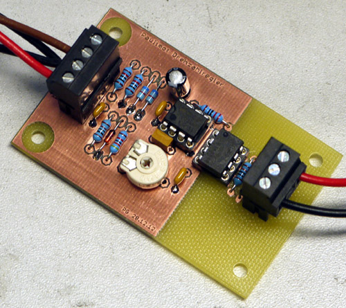
"In the original state, the speed is set with a potentiometer. What makes things a bit difficult is the fact that there is an AC voltage of approx. 125 V between the terminals of the potentiometer and the protective earth. So it is not done with simple electronics. A friend therefore developed the above circuit for me, which basically consists of an optocoupler with 5,000 V breakdown voltage, which serves as a controllable resistor and is driven by an operational amplifier, which in turn converts the control voltage of 0-10 V coming from the controller. The electronics of the machine and the control are thus completely galvanically isolated.
The output of the circuit replaces the potentiometer and thus controls the output frequency of the inverter and thus the speed of the motor. This allows me to regulate the spindle speed via software between 600 and 2,500 rpm, just as in the original state."The interface board

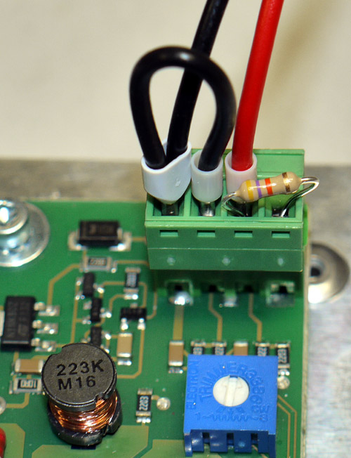
the connector on the spindle controller

Unfortunately, this is the only information available to this interface board, since the author is not available and the website was sold to a cnc-company who wants to keep the information available to the public.
So my question is: How can I adapt this optocoupler circuit to work with a PWM signal from the duet board?
Cheers Max
-
I followed your suggestion and a lookup table to pick the initial potentiometer position and then fine tune the spindle RPM with a loop.
This worked well enough for some initial tests. But for me, it was no satisfying permanent solution.After taking some voltage measurements, I figured that the motor controller simply needs a 0-5V Control Signal.

So I used a PWM to analog converter to provide the control signal and to galvanically separate the inverter from the Duet Board.
I am using a multifix toolpost to quickly change between tools. In order to avoid manually calibrating a new tool, I wrote a macro that can automatically set the offsets for a given tool using a touch probe. Since the multifix toolpost is very repeatable, the offsets do not need to be recalibrated after a toolchange.

I am very happy how this project turned out. The Duet3HC is a formidable controller for small CNC-Maschines.


Video: Paulimot CNC-converion test.mp4


Cheers
Max -
@maxgyver if that doesn't work out you could mechanically actuate the original potentiometer with a stepper. Certainly more than enough headroom with the 6HC
-
@3dpmicro said in Paulimot PM190 Lathe CNC-conversion:
@maxgyver if that doesn't work out you could mechanically actuate the original potentiometer with a stepper. Certainly more than enough headroom with the 6HC
Maybe as a quick fix, but since this has already been done I would prefer the electronic version.
-
Since I did not find a working alternative, I took your suggestion and designed a contraption that couples a Nema17 stepper motor to the potentiometer. Now I can control the spindle RPM via the Y-Axis. The step/mm of Y are calibrated to be at min RPM when the axis is homed and at max RPM when the axis is at 255mm. I chose 255mm as Y max in preparation for PWM control.
Don't mind the bad print quality, I printed with the wrong filament profile.


Now I need a spindle RPM feedback.
I would like to use the original sensor that is already built into the Lathe. It is an 24V NPN inductive sensor. Since spindle RPM feedback is not implemented in the firmware, I would like to use the Fan tach input. Conveniently, the Fan connector would also provide 24V VCC and ground. Since all inputs can be used up to 30V this should not be an issue.
-
@maxgyver I can certainly understand the desire to do things properly. You can always revisit the the controller once the machine is complete. That's what I tell myself anyway
-
I am making good progress with the lathe conversion. Yesterday, I finally CNC'd the parts from a 25mm aluminum plate. I was able to fit most of the new parts where the original bearing blocks used to be. I only had to add two M5 threaded holes to the top of the X carriage to mount the X-motor adapter.

Like mentioned in my last post, I am using an NPN inductive sensor connected to out4 to read the spindle RPM.
M950 F1 C"!out4+^out4.tach" C"Spindle RPM" ; create fan and use out4.tach for spindle RPM sensorI wrote a simple macro that is incrementally increasing or decreasing the position of the Motor-Potentiometer until the desired spindle RPM and the measured spindle sensor RPM are identical (or at least very close) If the difference between set RPM and sensor RPM is more than ±300RPM the increments are adjusted in larger steps. When the rpm get within ±30 RPM of the target, the increments are reduced. With this macro, I can reach every desired speed with a deviation of under 5RPM.
if !move.axes[1].homed  ;check if Y is homed. If not, home Y first.
 ;echo "Y-Axis not homed, homing Y-Axis first"
 M98 P"homey.g"
G91 ;relative moves

while spindles[0].active-fans[1].rpm > 2 || spindles[0].active-fans[1].rpm <-2
 if spindles[0].active-fans[1].rpm > 300
  G1 Y+2
 else
  if spindles[0].active-fans[1].rpm > 30
   G1 Y+1
  else
   if spindles[0].active-fans[1].rpm > 1
    G1 Y+0.1
 if spindles[0].active-fans[1].rpm < -300
  G1 Y-2
 else
  if spindles[0].active-fans[1].rpm <- 30
   G1 Y-1
  else
   if spindles[0].active-fans[1].rpm <-1
    G1 Y-0.1
 G4 S0.2

G90 ;absolute moves
M118 S"Spindle speed reached!"
Now I have to figure out how to call the macro whenever an M3 command is called...
Does anyone know which Fusion360 /HSM-Works turning-post processor works with the Duet3 ?
-Cheers Max
-
I think you need to take the spindles[0].active-fans[1].rpm and subtract it from SpindleDesiredRPM everytime you compare with something.
Like this:
if ( SpindleDesiredRPM - spindles[0].active-fans[1].rpm) <-1One thing that might make this faster would be to have a lookup table that takes the command speed and initially picks a close-enough stepper-motor position and starts there.
Then your macro can fine-tune and can maintain the speed under varying loads if you desire.
-
 undefined MaxGyver referenced this topic
-
I followed your suggestion and a lookup table to pick the initial potentiometer position and then fine tune the spindle RPM with a loop.
This worked well enough for some initial tests. But for me, it was no satisfying permanent solution.After taking some voltage measurements, I figured that the motor controller simply needs a 0-5V Control Signal.

So I used a PWM to analog converter to provide the control signal and to galvanically separate the inverter from the Duet Board.
I am using a multifix toolpost to quickly change between tools. In order to avoid manually calibrating a new tool, I wrote a macro that can automatically set the offsets for a given tool using a touch probe. Since the multifix toolpost is very repeatable, the offsets do not need to be recalibrated after a toolchange.

I am very happy how this project turned out. The Duet3HC is a formidable controller for small CNC-Maschines.


Video: Paulimot CNC-converion test.mp4


Cheers
Max -
 undefined MaxGyver has marked this topic as solved
-
 undefined MaxGyver referenced this topic
-
 undefined MaxGyver referenced this topic