Extreme VFA in prints..
-
Hi all,
I recently upgraded my FT-5 printer to a duet 3 mini 5+. Since the upgrade, I'm getting an extreme amount of VFA ripples in my prints. Can someone advise the best approach to fixing this? I didn't have this issue before. It feels like the motors are inducing the vibration (which I would expect with VFA). Is stealthchop/spreadcycle enabled on the board by default? How can I check this?
Thanks
-
@aquaticlife What's VFA ripples?
-
@alankilian It looks like ghosting/ringing but is present at a continuous interval and independent of features in the print.
-
@aquaticlife said in Extreme VFA in prints..:
Is stealthchop/spreadcycle enabled on the board by default? How can I check this?
I'd guess it's changing over from stealthChop to spreadCycle at a speed close to your normal printing speed, which is causing the VFAs.
Post your config.g and response to M115. For each motor, send
M569 P[motor driver number]to see each individual motor's settings. The default is spreadCycle for all drivers from RRF 3.4, and stealthChop2 for TMC22xx (ie Mini 5+) in RRF 3.3 and earlier. In stealthChop mode the drivers will switch over to spreadCycle automatically at high speeds, set by the V parameter.For configuring stealthChop, see https://docs.duet3d.com/en/User_manual/Connecting_hardware/Motors_tuning#configuring-stealthchop
We suggest the use of one of the following configurations:
- stealthChop changing over to spreadCycle a very low speed. Compared to running in spreadCycle always, this reduces standstill noise with some motors.
- stealthChop changing over to spreadCycle at a little over your normal maximum printing speed. It will switch to spreadCycle for travel moves, except very short ones. This will only be viable if the jerk at switchover is tolerable.
- Limit your travel speed so that you can keep the printer in stealthChop mode always.
I tend to run my Mini 5+ in stealthChop mode always, with
M569 P0.0 S0 D3 V0.Ian
Bed-slinger - Mini5+ WiFi/1LC | RRP Fisher v1 - D2 WiFi | Polargraph - D2 WiFi | TronXY X5S - 6HC/Roto | CNC router - 6HC | Tractus3D T1250 - D2 Eth
-
m115
FIRMWARE_NAME: RepRapFirmware for Duet 3 Mini 5+ FIRMWARE_VERSION: 3.4.1 ELECTRONICS: Duet 3 Mini5plus WiFi FIRMWARE_DATE: 2022-06-01 21:07:06; Configuration file for Duet 3 Mini 5+ (firmware version 3.3)
; executed by the firmware on start-up
;
; generated by RepRapFirmware Configuration Tool v3.3.12 on Mon Aug 01 2022 12:37:08 GMT-0500 (Central Daylight Saving Time); General preferences
G90 ; send absolute coordinates...
M83 ; ...but relative extruder moves
M550 P"FT-5 DUET 3 MINI 5+1.0" ; set printer name; Wait a moment for the CAN expansion boards to start
G4 S2; Network
M552 S1 ; enable network
M586 P0 S1 ; enable HTTP
M586 P1 S0 ; disable FTP
M586 P2 S0 ; disable Telnet; Drives
M569 P0.0 S1 D3 V0 ; physical drive 0.0 goes forwards (MODIFIED TO S1 D3 V0)
M569 P0.1 S1 D3 V0 ; physical drive 0.1 goes forwards (MODIFIED TO S1 D3 V0)
M569 P0.3 S0 D3 V0 ; physical drive 0.3 goes backwards (MODIFIED TO S0 D3 V0)
M569 P121.0 S1 D3 V0 ; physical drive 121.0 goes forwards (MODIFIED TO S1 D3 V0)
M584 X0.0 Y0.1 Z0.3 E121.0 ; set drive mapping
M350 X16 Y16 Z16 E16 I1 ; configure microstepping with interpolation
M92 X80.00 Y80.00 Z400.00 E415.00 ; set steps per mm
M566 X900.00 Y900.00 Z60.00 E120.00 ; set maximum instantaneous speed changes (mm/min)
M203 X18000.00 Y18000.00 Z300.00 E1500.00 ; set maximum speeds (mm/min)
M201 X800.00 Y800.00 Z200.00 E10000.00 ; set accelerations (mm/s^2)
M906 X800 Y800 Z800 E800 I30 ; set motor currents (mA) and motor idle factor in per cent
M84 S30 ; Set idle timeout; Axis Limits
M208 X0 Y0 Z0 S1 ; set axis minima
M208 X300 Y300 Z400 S0 ; set axis maxima; Endstops
M574 X1 S1 P"!io0.in" ; configure switch-type (e.g. microswitch) endstop for low end on X via pin io0.in
M574 Y1 S1 P"!io1.in" ; configure switch-type (e.g. microswitch) endstop for low end on Y via pin io1.in
M574 Z1 S1 P"!io2.in" ; configure switch-type (e.g. microswitch) endstop for low end on Z via pin io2.in; Z-Probe
M558 P0 ;M558 P1 C"121.io0.in" H5 F120 T6000 ; set Z probe type to unmodulated and the dive height + speeds DISABLED FOR MOMENT
;G31 P500 X27.783 Y7.7 Z2.5 ; set Z probe trigger value, offset and trigger height DISABLED FOR MOMENT
;M557 X15:215 Y15:195 S20 ; define mesh grid DISABLED FOR MOMENT; Heaters
M308 S0 P"temp0" Y"thermistor" T100000 B4138 ; configure sensor 0 as thermistor on pin temp0
M950 H0 C"out0" T0 ; create bed heater output on out0 and map it to sensor 0
M307 H0 B0 R0.275 C415.4 D8.75 S1.00 V24.2 ; disable bang-bang mode for the bed heater and set PWM limit
M140 H0 ; map heated bed to heater 0
M143 H0 S100 ; set temperature limit for heater 0 to 100C
M308 S1 P"121.temp0" Y"thermistor" T100000 B4267 ; configure sensor 1 as thermistor on pin 121.temp0
M950 H1 C"121.out0" T1 ; create nozzle heater output on 121.out0 and map it to sensor 1
M307 H1 B0 R2.114 C255.4:136.0 D6.76 S1.00 V24.2 ; disable bang-bang mode for heater and set PWM limit
M143 H1 S250 ; set temperature limit for heater 1 to 250C; Fans
M950 F0 C"121.out1" Q500 ; create fan 0 on pin 121.out1 and set its frequency
M106 P0 S0 H-1 ; set fan 0 value. Thermostatic control is turned off
M950 F1 C"121.out2" Q500 ; create fan 1 on pin 121.out2 and set its frequency
M106 P1 S1 H1 T45 ; set fan 1 value. Thermostatic control is turned on; Tools
M563 P0 D0 H1 F0 ; define tool 0
; M572 D0 S0.25 ; define pressure advance REMOVED - SEE FILAMENT GCODE
G10 P0 X0 Y0 Z0 ; set tool 0 axis offsets
G10 P0 R0 S0 ; set initial tool 0 active and standby temperatures to 0C; Custom settings are not defined
M955 P121.0 I54 ;accelerometer added
M593 P"zvddd" F24.6 ;input shaping -
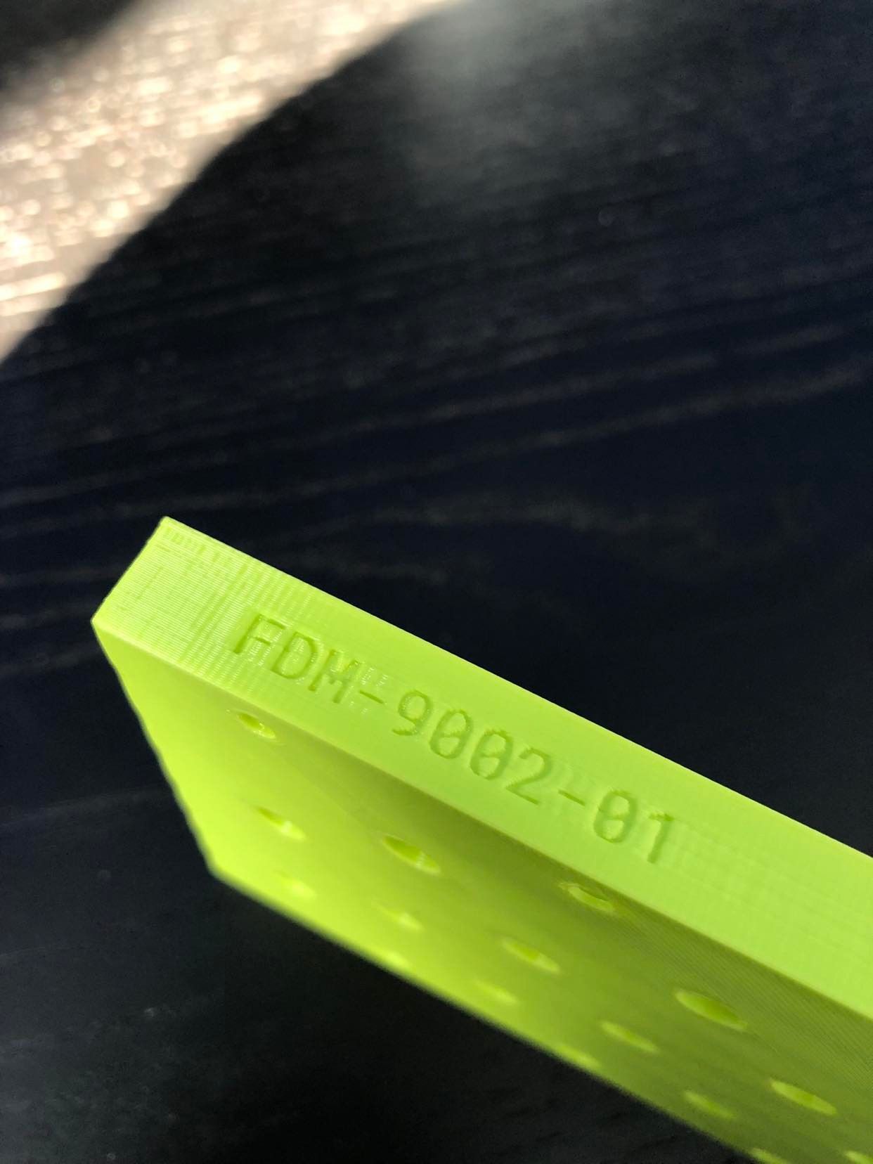
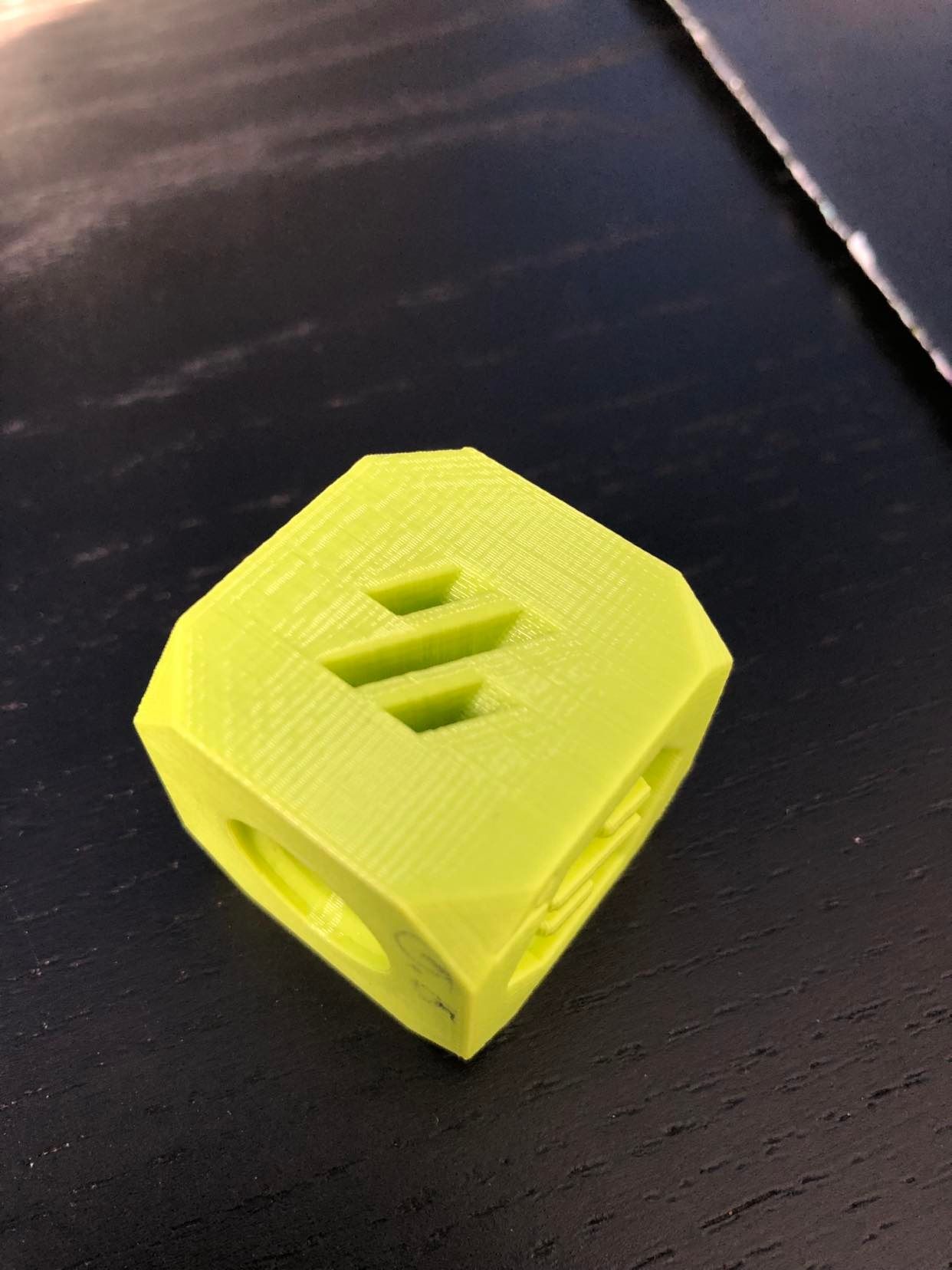
@droftarts Here's a closeup of the VFA. I've set stealthchop to always be on, ran pressure advance and input shaping, changed my belts to new gates belts, cleaned the bearings, etc. Not sure if this is something that can actually be eliminated in your experience.
-
@aquaticlife said in Extreme VFA in prints..:
I didn't have this issue before.
Do you have the details of your previous configuration? So acceleration rates, jerk settings, print speeds, motor currents etc? What firmware was used on the FT-5 before you switched to RRF?
It is hard to tell from the pictures, but do the ripples extend all the way to the end of each side? It looks in the above image as if they start at the left side (or at features in the print), but fade out towards the right side.