Problems wiring & configuring fans
-
@rushmere3d Hi this is a cut and paste of my config.g file
 Configuration file for Duet 3 (firmware version 3)
; executed by the firmware on start-up
;
; generated by RepRapFirmware Configuration Tool v3.2.3 on Sat May 08 2021 00:14:11 GMT+0100 (British Summer Time)

; General preferences
G90                                          ; send absolute coordinates...
M83                                          ; ...but relative extruder moves
M550 P"Hevort"                               ; set printer name
M669 K1                                      ; select CoreXY mode

; Network
M552 P0.0.0.0 S1                             ; enable network and acquire dynamic address via DHCP
M586 P0 S1                                   ; enable HTTP
M586 P1 S0                                   ; disable FTP
M586 P2 S0                                   ; disable Telnet

; Drives
M569 P0.0 S1                                 ; physical drive 0.0 goes forwards
M569 P0.1 S1                                 ; physical drive 0.1 goes forwards
M569 P0.2 S1                                 ; physical drive 0.2 goes forwards
M569 P0.3 S1                                 ; physical drive 0.3 goes forwards
M584 X0.1 Y0.2 Z0.5:0.4:0.3 E0.0             ; set drive mapping
M671 X-30.0:164.4:362.8 Y-30.0:298.8:-30.0   ; z leadscrew positions
M350 X16 Y16 Z16 E16 I1                      ; configure microstepping with interpolation
M92 X80.00 Y80.00 Z400.00 E420.00            ; set steps per mm
M566 X900.00 Y900.00 Z60.00 E120.00          ; set maximum instantaneous speed changes (mm/min)
M203 X6000.00 Y6000.00 Z180.00 E1200.00      ; set maximum speeds (mm/min)
M201 X500.00 Y500.00 Z20.00 E250.00          ; set accelerations (mm/s^2)
M906 X1200 Y1200 Z1200 E1100 I30             ; set motor currents (mA) and motor idle factor in per cent
M84 S30                                      ; Set idle timeout

; Axis Limits
M208 X0 Y0 Z0 S1                             ; set axis minima
M208 X330 Y315 Z340 S0                       ; set axis maxima

; Endstops
M574 X1 S1 P"!io0.in"                        ; configure active-high endstop for low end on X via pin !io0.in
M574 Y1 S1 P"!io1.in"                        ; configure active-high endstop for low end on Y via pin !io1.in

; Z-Probe
M950 S0 C"io7.out"                           ; create servo pin 0 for BLTouch
M558 P9 C"^io7.in" H5 F120 T6000             ; set Z probe type to bltouch and the dive height + speeds
M558 H30                                     ;*** Remove this line after delta calibration has been done and new delta parameters have been saved
G31 P500 X30 Y40 Z2.5                        ; set Z probe trigger value, offset and trigger height
M557 X15:215 Y15:195 S20                     ; define mesh grid

; Heaters & Sensors
M308 S0 P"temp0" Y"thermistor" T100000 B3950 ; configure sensor 0 as thermistor on pin temp0               BED TEMP
M950 H0 C"out0" T0                           ; create bed heater output on out0 and map it to sensor 0
M307 H0 B1 S1.00                             ; enable bang-bang mode for the bed heater and set PWM limit
M140 H0                                      ; map heated bed to heater 0
M143 H0 S120                                 ; set temperature limit for heater 0 to 120C
M308 S1 P"temp1" Y"pt1000" R2200             ; configure sensor 1 as PT1000 on pin temp1                   EXTRUDER TEMP
M950 H1 C"out1" T1                           ; create nozzle heater output on out1 and map it to sensor 1
M307 H1 B0 S1.00                             ; disable bang-bang mode for heater  and set PWM limit
M143 H1 S280                                 ; set temperature limit for heater 1 to 280C
M308 S2 A"Chamber" P"temp2" Y"thermistor" T100000 B4138 ; configure sensor 0 as thermistor on pin temp2    CHAMBER TEMP SENSOR
M308 S10 Y"mcu-temp" A"MCU"                  ; defines sensor 10 as MCU temperature sensor                 MCU TEMP SENSOR
M308 S11 Y"drivers" A"Stepper Drivers"       ; defines sensor 11 as stepper driver temperature             STEPPER TEMP SENSOR


; Fans
M950 F0 C"out4" Q500                         ; create fan 0 on pin out4 and set its frequency              PART COOLING FAN
M106 P0 S0 H-1                               ; set fan 0 value. Thermostatic control is turned oFF
M950 F1 C"out5" Q500                         ; create fan 1 on pin out7 and set its frequency              EXTRUDER FAN
M106 P1 S1 H1 T45                            ; set fan 1 value. Thermostatic control is turned on
;M950 F2 C"out5" Q500                         ; create fan 2 on pin out5 and set its frequency              MCU COOLING FAN
;M106 P2 H10:11 T40:70                        ; set fan 2 value. Thermostatic control is turned on
;M950 F3 C"out6" Q500                         ; create fan 3 on pin out6 and set its frequency              CHAMBER FAN
;M106 P3 S0.7 H2 T60                          ; set fan 3 value. Thermostatic control is turned on


; Tools
M563 P0 D0 H1 F0                             ; define tool 0
G10 P0 X0 Y0 Z0                              ; set tool 0 axis offsets
G10 P0 R0 S0                                 ; set initial tool 0 active and standby temperatures to 0C

; Custom settings are not defined

; Miscellaneous
M501                                         ; load saved parameters from non-volatile memory
I hope this helps, I have commented out the other fans I originally planned to use, going one step at a time and also realising the limitations
-
I hope this is clear enough
") I'm not great with paint
I'm not great with paint -
@ce72 How are the two three-pin jumpers above OUT4 to OUT9 set? These control the voltage to each bank of OUT connectors. The E3D fan needs 24V. Do you have the 12V or 24V version of the CPAP fan controller? The fan needs to be supplied with that voltage continuously. The fan controller also says it needs a "Input 0-5V DC signal to change motor speed", so 0V to 5V variable, not PWM.
Ian
Bed-slinger - Mini5+ WiFi/1LC | RRP Fisher v1 - D2 WiFi | Polargraph - D2 WiFi | TronXY X5S - 6HC/Roto | CNC router - 6HC | Tractus3D T1250 - D2 Eth
-
@ce72
I don't think the way you have the VSR wired is correct. Looking at the aliexpress listing, the VSR accepts a 0-5v analogue control signal to set the fan speed. RRF provides PWM signals which won't work. You'll need something like a PWM to analogue converter (which is the same way I control my CNC spindle). https://www.amazon.co.uk/Voltage-Converter-Analog-0-100-2KHZ-20KHZ/dp/B07SZ8JYLTThe E3D fan wiring however looks correct. It is worth checking how you have the jumper set just above OUT4 (the Low current output voltage input).
Owns various duet boards and is the main wiki maintainer for the Teamgloomy LPC/STM32 port of RRF. Assume I'm running whatever the latest beta/stable build is
-
@droftarts
Both jumpers set to V Fused, I Originally I had outputs 4-6 set to 12v, but after my first problem with "out7" i changed 4-6 onto the Vfused jumper. -
@jay_s_uk
If anything I thought this could be my problem and where my knoledge run out, would this give me the same solution? https://www.ebay.co.uk/itm/194326627552 . As the one you linked was out of stock. -
@ce72 No, that ones the wrong way. you need PWM to voltage like this https://www.ebay.co.uk/itm/194326642791
-
@jay_s_uk
Thank you for pointing that out, the fun of google search same words wrong place
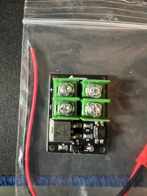
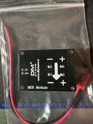
On the the off chance and please pardon my ignorance here, but I have got this with another air pump system, would it be what I need?
If not I will happily grab the one you linked to
-
@ce72 looks like an external mosfet for when the onboard ones aren't powerful enough. It won't help you in this instance
-
@jay_s_uk That's fair enough. I have just ordered the one that you linked, The next question is could you tell me how I need to wire it in and configure it
-
@ce72 you'd wire it as you have your fan. The output from the PWM to analog would then go to the VSR for the speed. Then just configure it as a normal fan
-
@jay_s_uk so if I understand you correctly that would be
"out4" jumper in VFused
pin1 = GND:Ground
pin2 = VCC:DC 12V-30V
pin3 = PWM:Positive of PWM input signal
pin4 = GND:Negative of input signal"fan control board"
VSR = VOUT:Output Voltage 0-10V
GND = GND:Output Voltage Ground
PG = Not connectedIs this is for the 24v version of the Cpap?
You also mentioned earlier about the frequency on the E3d fan? how do I determine this value and could this be the reason for it not working at the moment
Thank you for all your help it is very much appreciated, As I feel like I have been banging my head against a brick wall trying to work this out
-
@ce72 "Qnn (optional) PWM frequency in Hz. Valid range: 0-65535, default: 500 for GpOut pins, 250 for fans and heaters"
-
@ce72 no, it would be provide 24v directly to the VSR from your PSU.
connect between V_OUTLC1 (+) and out4 (-) to the input of the PWM to analog converter.
the PWM to analog would then just need to connect the + and - to the VSR 0-5v input and ground. Make sure you set the PWM to analog to 5v mode rather than 10v. -
@jay_s_uk oh fair enough, thank you for pointing that out, I will check the output before fully conecting them up.
I'll post back with the outcome when the convertor arrives
thank you again
-
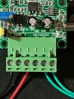
@ce72 I have received my PWM to voltage converter and I'm have troubles connecting it and getting the right output. I have checked the port on the board with a pigtail and multimeter and I'm getting the right output from there as it is the same as the other ports which are now working.
Here is how I'm trying to connect the converter
port6
V_OUTLC1 red wire to 12-30V on the converter
OUT6(-) black wire to PWM- on the converteryellow & blue going to the multimeter (leave other components out of the way)
I'm only getting 0.2v out
Please advise (I've managed to get the acceleromter working no problem, but I'm getting beaten by a fan
) -
@ce72 what have you connected the PWMIN+ wire on the converter to? And the GND side of the 12-30V power input?
PS - also, which of the 2 drivers on that page linked to in the original post are you using with it: the 12V one or the 24V one?
Duet WiFi hardware designer and firmware engineer
Please do not ask me for Duet support via PM or email, use the forum
http://www.escher3d.com, https://miscsolutions.wordpress.com -
@dc42 Hi, I've got the 24v variant, so I could provide power straight from the PSU.
Regarding the wiring, I tried connecting:
6HC (out5) converter
pin1 (GND) GND on the 12-30V side
pin2 (VIN) 12-30V
pin3 (out5.tach) PWM +
pin4 (out5) PWM -I had a multimeter across AO and ground on the output, (rather than connecting anything else) and had an output of 0 - 0.48V that varied with the "s" parameter.
VIN was 23.9V on the same multimeter
I hope this helps to find where I have gone wrong
-
@ce72 PWM+ needs to be connected to +5V (if you have the jumper on the convertor set to 5V) or VIN (if you have the jumper on the converter removed so that it can accept 24V). Do not connect anything to the out5.tach pin unless the fan has a tacho output.
As an alternative to using the PWM-to-voltage converter, the following may work (the driver description on that site gives very limited details, so it's hard to be sure):
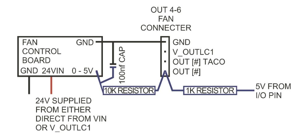
- Connect the fan driver power wires as now (negative to GND and positive to VIN, either directly or on the fan connector, with the fan voltage jumper set appropriately)
- Connect a 1K resistor between out5_neg and +5V (you can find +5V on the IO_ connectors)
- Connect a 10K resistor between out5_neg and fan 0-5V in
- Also connect a capacitor of 100nf (0.1uf) or greater between fan 0-5V and ground
- In the M950 command for that fan, set the frequency (Q parameter) to the maximum, which is 65535
Duet WiFi hardware designer and firmware engineer
Please do not ask me for Duet support via PM or email, use the forum
http://www.escher3d.com, https://miscsolutions.wordpress.com -
@dc42 Sorry to be a pain but to clarify. and so that I fully understand, Am I right with these two options in sketch form:
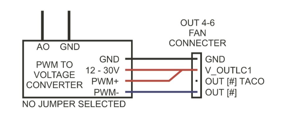
OR