Duet3D Logo Duet3D
    • Tags
    • Documentation
    • Order
    • Register
    • Login

    Problems wiring & configuring fans

    Scheduled Pinned Locked Moved
    Duet Hardware and wiring
    5
    24
    1.0k
    Loading More Posts
    • Oldest to Newest
    • Newest to Oldest
    • Most Votes
    Reply
    • Reply as topic
    Log in to reply
    This topic has been deleted. Only users with topic management privileges can see it.
    • jay_s_ukundefined
      jay_s_uk @Ce72
      last edited by jay_s_uk

      @ce72
      I don't think the way you have the VSR wired is correct. Looking at the aliexpress listing, the VSR accepts a 0-5v analogue control signal to set the fan speed. RRF provides PWM signals which won't work. You'll need something like a PWM to analogue converter (which is the same way I control my CNC spindle). https://www.amazon.co.uk/Voltage-Converter-Analog-0-100-2KHZ-20KHZ/dp/B07SZ8JYLT

      The E3D fan wiring however looks correct. It is worth checking how you have the jumper set just above OUT4 (the Low current output voltage input).

      Owns various duet boards and is the main wiki maintainer for the Teamgloomy LPC/STM32 port of RRF. Assume I'm running whatever the latest beta/stable build is

      Ce72undefined 1 Reply Last reply Reply Quote 0
      • Ce72undefined
        Ce72 @droftarts
        last edited by

        @droftarts
        Both jumpers set to V Fused, I Originally I had outputs 4-6 set to 12v, but after my first problem with "out7" i changed 4-6 onto the Vfused jumper.

        1 Reply Last reply Reply Quote 0
        • Ce72undefined
          Ce72 @jay_s_uk
          last edited by

          @jay_s_uk
          If anything I thought this could be my problem and where my knoledge run out, would this give me the same solution? https://www.ebay.co.uk/itm/194326627552 . As the one you linked was out of stock.

          jay_s_ukundefined 1 Reply Last reply Reply Quote 0
          • jay_s_ukundefined
            jay_s_uk @Ce72
            last edited by

            @ce72 No, that ones the wrong way. you need PWM to voltage like this https://www.ebay.co.uk/itm/194326642791

            Owns various duet boards and is the main wiki maintainer for the Teamgloomy LPC/STM32 port of RRF. Assume I'm running whatever the latest beta/stable build is

            Ce72undefined 1 Reply Last reply Reply Quote 0
            • Ce72undefined
              Ce72 @jay_s_uk
              last edited by

              @jay_s_uk
              Thank you for pointing that out, the fun of google search same words wrong place 😕

              On the the off chance and please pardon my ignorance here, but I have got this with another air pump system, would it be what I need?

              pic1.jpg
              pic2.jpg

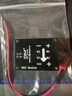
              If not I will happily grab the one you linked to

              jay_s_ukundefined 1 Reply Last reply Reply Quote 0
              • jay_s_ukundefined
                jay_s_uk @Ce72
                last edited by

                @ce72 looks like an external mosfet for when the onboard ones aren't powerful enough. It won't help you in this instance

                Owns various duet boards and is the main wiki maintainer for the Teamgloomy LPC/STM32 port of RRF. Assume I'm running whatever the latest beta/stable build is

                Ce72undefined 1 Reply Last reply Reply Quote 0
                • Ce72undefined
                  Ce72 @jay_s_uk
                  last edited by

                  @jay_s_uk That's fair enough. I have just ordered the one that you linked, The next question is could you tell me how I need to wire it in and configure it

                  jay_s_ukundefined 1 Reply Last reply Reply Quote 0
                  • jay_s_ukundefined
                    jay_s_uk @Ce72
                    last edited by

                    @ce72 you'd wire it as you have your fan. The output from the PWM to analog would then go to the VSR for the speed. Then just configure it as a normal fan

                    Owns various duet boards and is the main wiki maintainer for the Teamgloomy LPC/STM32 port of RRF. Assume I'm running whatever the latest beta/stable build is

                    1 Reply Last reply Reply Quote 0
                    • Ce72undefined
                      Ce72
                      last edited by

                      @jay_s_uk so if I understand you correctly that would be

                      "out4" jumper in VFused
                      pin1 = GND:Ground
                      pin2 = VCC:DC 12V-30V
                      pin3 = PWM:Positive of PWM input signal
                      pin4 = GND:Negative of input signal

                      "fan control board"
                      VSR = VOUT:Output Voltage 0-10V
                      GND = GND:Output Voltage Ground
                      PG = Not connected

                      Is this is for the 24v version of the Cpap?

                      You also mentioned earlier about the frequency on the E3d fan? how do I determine this value and could this be the reason for it not working at the moment

                      Thank you for all your help it is very much appreciated, As I feel like I have been banging my head against a brick wall trying to work this out 🙂

                      Rushmere3Dundefined jay_s_ukundefined 2 Replies Last reply Reply Quote 0
                      • Rushmere3Dundefined
                        Rushmere3D @Ce72
                        last edited by

                        @ce72 "Qnn (optional) PWM frequency in Hz. Valid range: 0-65535, default: 500 for GpOut pins, 250 for fans and heaters"

                        Follow my adventures in 3D Printing, laser cutting and electronics. https://linktr.ee/Rushmere3D

                        1 Reply Last reply Reply Quote 0
                        • jay_s_ukundefined
                          jay_s_uk @Ce72
                          last edited by

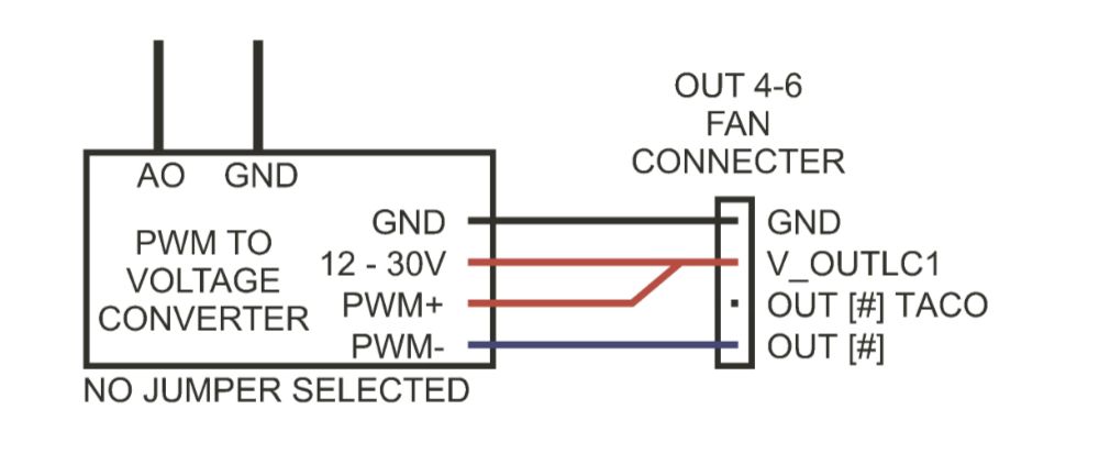
                          @ce72 no, it would be provide 24v directly to the VSR from your PSU.
                          connect between V_OUTLC1 (+) and out4 (-) to the input of the PWM to analog converter.
                          the PWM to analog would then just need to connect the + and - to the VSR 0-5v input and ground. Make sure you set the PWM to analog to 5v mode rather than 10v.

                          Owns various duet boards and is the main wiki maintainer for the Teamgloomy LPC/STM32 port of RRF. Assume I'm running whatever the latest beta/stable build is

                          Ce72undefined 1 Reply Last reply Reply Quote 0
                          • Ce72undefined
                            Ce72 @jay_s_uk
                            last edited by

                            @jay_s_uk oh fair enough, thank you for pointing that out, I will check the output before fully conecting them up.

                            I'll post back with the outcome when the convertor arrives

                            thank you again

                            Ce72undefined 1 Reply Last reply Reply Quote 1
                            • Ce72undefined
                              Ce72 @Ce72
                              last edited by

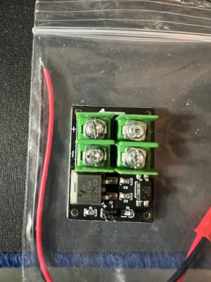
                              @ce72 I have received my PWM to voltage converter and I'm have troubles connecting it and getting the right output. I have checked the port on the board with a pigtail and multimeter and I'm getting the right output from there as it is the same as the other ports which are now working.

                              Here is how I'm trying to connect the converter

                              port6
                              V_OUTLC1 red wire to 12-30V on the converter
                              OUT6(-) black wire to PWM- on the converter

                              yellow & blue going to the multimeter (leave other components out of the way)

                              I'm only getting 0.2v out

                              pwm converter.jpeg

                              Please advise (I've managed to get the acceleromter working no problem, but I'm getting beaten by a fan 😕 )

                              dc42undefined 1 Reply Last reply Reply Quote 0
                              • dc42undefined
                                dc42 administrators @Ce72
                                last edited by dc42

                                @ce72 what have you connected the PWMIN+ wire on the converter to? And the GND side of the 12-30V power input?

                                PS - also, which of the 2 drivers on that page linked to in the original post are you using with it: the 12V one or the 24V one?

                                Duet WiFi hardware designer and firmware engineer
                                Please do not ask me for Duet support via PM or email, use the forum
                                http://www.escher3d.com, https://miscsolutions.wordpress.com

                                Ce72undefined 1 Reply Last reply Reply Quote 0
                                • Ce72undefined
                                  Ce72 @dc42
                                  last edited by

                                  @dc42 Hi, I've got the 24v variant, so I could provide power straight from the PSU.

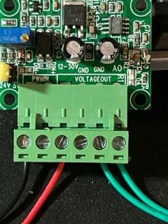
                                  Regarding the wiring, I tried connecting:

                                  6HC (out5) converter
                                  pin1 (GND) GND on the 12-30V side
                                  pin2 (VIN) 12-30V
                                  pin3 (out5.tach) PWM +
                                  pin4 (out5) PWM -

                                  I had a multimeter across AO and ground on the output, (rather than connecting anything else) and had an output of 0 - 0.48V that varied with the "s" parameter.

                                  VIN was 23.9V on the same multimeter

                                  I hope this helps to find where I have gone wrong

                                  dc42undefined 1 Reply Last reply Reply Quote 0
                                  • dc42undefined
                                    dc42 administrators @Ce72
                                    last edited by

                                    @ce72 PWM+ needs to be connected to +5V (if you have the jumper on the convertor set to 5V) or VIN (if you have the jumper on the converter removed so that it can accept 24V). Do not connect anything to the out5.tach pin unless the fan has a tacho output.

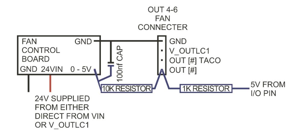
                                    As an alternative to using the PWM-to-voltage converter, the following may work (the driver description on that site gives very limited details, so it's hard to be sure):

                                    • Connect the fan driver power wires as now (negative to GND and positive to VIN, either directly or on the fan connector, with the fan voltage jumper set appropriately)
                                    • Connect a 1K resistor between out5_neg and +5V (you can find +5V on the IO_ connectors)
                                    • Connect a 10K resistor between out5_neg and fan 0-5V in
                                    • Also connect a capacitor of 100nf (0.1uf) or greater between fan 0-5V and ground
                                    • In the M950 command for that fan, set the frequency (Q parameter) to the maximum, which is 65535

                                    Duet WiFi hardware designer and firmware engineer
                                    Please do not ask me for Duet support via PM or email, use the forum
                                    http://www.escher3d.com, https://miscsolutions.wordpress.com

                                    Ce72undefined 1 Reply Last reply Reply Quote 0
                                    • Ce72undefined
                                      Ce72 @dc42
                                      last edited by

                                      @dc42 Sorry to be a pain but to clarify. and so that I fully understand, Am I right with these two options in sketch form:

                                      CONVERTER WIRING 1.jpg

                                      OR

                                      BLOWER WIRING 2.jpg

                                      Ce72undefined 1 Reply Last reply Reply Quote 0
                                      • Ce72undefined
                                        Ce72 @Ce72
                                        last edited by

                                        @ce72
                                        I wired up the PWM to voltage converter as above, and found I needed the jumper to get an output. So I put the jumper in the 24v side and I was able to tune the voltage down to around 6.5v output, from this i added a "F" value on the M106 line of my config file to limit the output to the required 5v with full control.

                                        I'm pleased to say all is now working great 🙂 I will also order the required risistors and cap to try the other way, to make a cleaner install and not need the work around in the config.

                                        1 Reply Last reply Reply Quote 0
                                        • First post
                                          Last post
                                        Unless otherwise noted, all forum content is licensed under CC-BY-SA