Mushrooming print - What could cause this?
-
@leav

Great... congratulations.
This problem was somehow exciting, so you wanted to know what the problem was.
So the filament didn't contract, it just melted and the walls collapsed.That it shrinks in the middle and not at the top and bottom... that didn't fit together.
If a filament were to shrink so extremely, it would detach from the print bed very quickly.
This is why some nylon (PA) and polycarbonate (PC) filaments etc. are so difficult to print because they contract and loosen on the print bed.If you have new filaments, focus primarily on the temperatures specified by the manufacturer.
Then print a heat tower to determine the ideal temperature for this particular spool of filament.
To adjust this filament even more precisely...
Determine the perfect flow, measure the diameter of the filament, measure the thickness of the printed walls, etc pp.And if you really want to know
 then a shrinkage test print would be the order of the day, simply print a 5mm -10mm high cross in the X-Y direction, which you can still measure with your caliper, i.e. 100mm to 150mm length of the struts.
Remove the finished printed cross from the print bed and let it cool down completely to room temperature !!! and then measure the difference and then enter it in the slicer so that the next print is printed "larger" by this value in order to obtain dimensionally accurate printed parts.
But I only do that if the dimensions of the component are important and you might be building different printed plastics and other materials together.
Otherwise I omit the specification in the slicer, since it is generally only a few tenths of a millimeter (depending on the size of the printed part and the type of filament).
In the slicer (PrusaSlicer) I have a page for comments for each filament, where I write down the values to transfer them to the slicer if necessary so that they are calculated.An example: ABS-X from Minadax (one of my favorites) I would have to slice at 100.5% magnification to get exact prints.
The ASA+ from PrimaSelect, which I mentioned and linked here, would have to be printed with 100.7% oversize.All these tests should be done with every filament, even an ABS from company A is different from an ABS from company B.
Maybe this information will help you to have more fun and less trouble with 3D printing in the future!?It would be great if you could send one last photo.
Maybe even a cog with the problem and a current cog next to it.
I would be interested in the end result, because the GIF doesn't show how well the print has become.
The top should also be visible.
Thanks !Sorry for the long text... I often write entire novels... one of my problems

Google Translate
--- Original Text ---Super... Gratuliere.
Dieses Problem war schon irgendwie spannend, da wollte man wissen woran es nun gelegen hat.
Das Filament hat sich also nicht zusammengezogen sondern es ist schlichtweg geschmolzen und die Wände sind eingestürzt.Das es sich in der Mitte schrumpft und Oben und Unten nicht... dass passte nicht zusammen.
Wenn ein Filament so extrem schrumpfen würde, dann würde es sich sehr schnell vom Druckbett lösen.
Deswegen sind manche Nylon (PA) und Polycarbonat (PC) Filamente etc. so schwer zu drucken, weil sie sich auf dem Druckbett zusammen ziehen und sich lösen.Wenn Du neue Filamente hast, richte Dich in erster Linie an die Temperaturen die der Hersteller vorgegeben hat.
Dann drucke einen Heattower um die ideale Temperatur für speziell diese Filamentrolle zu ermitteln.
Um dieses Filament noch genauer einzustellen...
Ermittle den perfekten Fluss, mit Filament-Durchmesser messen, die Stärke der gedruckten Wände messen etc pp.Und wenn Du es dann wirklich wissen willst
 dann wäre ein Schrumpf-Testdruck angesagt, dazu einfach ein 5mm -10mm hohes Kreuz in X-Y Richtung drucken, welches Du mit Deinem Messschieber noch messen kannst, also 100mm bis 150mm länge der Streben.
Löse das fertig gedruckte Kreuz vom Druckbett und lasse es komplett auf Raumtemperatur abkühlen !!! und messe dann die Differenz und trage sie dann im Slicer ein damit der nächste Druck um diesen Wert "größer" gedruckt wird, um masshaltige Druckteile zu erhalten.
Das mache ich aber nur, wenn die Maße des Bauteils wichtig sind und man ggf verschiedene gedruckte Kunststoffe und andere Materialien zusammen baut.
Ansonsten lasse ich die Angabe im Slicer weg, da es im Allgemeinen nur wenige Zehntel-Millimeter sind (Je nach Größe des Druckteils und Art des Filaments).
Im Slicer (PrusaSlicer) habe ich für jedes Filament eine Seite für Anmerkungen, dort notiere ich die Werte um sie bei Bedarf im Slicer zu übertragen damit sie mit berechnet werden.Ein Beispiel: ABS-X von Minadax (einer meiner Favoriten) müsste ich mit 100,5% Vergrößerung slicen um exakte Ausdrucke zu erhalten.
Das ASA+ von PrimaSelect, welches ich hier mal erwähnt und verlinkt hatte, müsste mit 100,7% Übergröße gedruckt werden.Diese ganzen Tests sollte man bei jedem Filament machen, selbst ein ABS von Firma A ist anders wie ein ABS von Firma B.
Vielleicht helfen Dir diese Infos um in Zukunft mehr Spaß und weniger Ärger beim 3D-Druck zu haben !?Es wäre toll wenn Du noch ein letztes Foto schicken könntest.
Vielleicht sogar ein Zahnrad mit dem Problem und ein aktuelles Zahnrad daneben.
Mich würde das End-Resultat interessieren, denn in dem GIF ist es nicht so gut zu erkennen wie gut der Druck jetzt geworden ist.
Die Oberseite sollte auch zu sehen sein.
Danke !Sorry für den langen Text... ich schreibe oft ganze Romane... einer meiner Probleme

-
Addendum
I have a 20mm x 20mm test cube here with four walls of different thickness.
0.4mm, 0.8mm, 1.2mm and 1.6mm thickness.
With this you can quickly determine the flow or balance your own values in terms of stability and accuracy.I had forgotten... you should also determine your own pressure advance value for each filament.
I'm sure I've forgotten something... that's how it is with age.

Unfortunately, it was not possible to upload a 3mf version, so it became a binary stl.
I hope you can do something with it and that it helps you.
(see link below)Google Translate
--- Original Text ---Nachtrag
Ich habe hier mal ein 20mm x 20mm Testwürfel mit vier unterschiedlichen dicken Wänden.
0,4mm, 0,8mm, 1,2mm und 1,6mm Stärke.
Damit kann man schnell mal den Fluss ermitteln bzw seine eigenen Werte ausbalancieren was Stabilität und Genauigkeit angeht.Ich hatte noch vergessen... man sollte für jedes Filament auch seinen eigenen Pressure Advance Wert ermitteln.
Ich habe garantiert noch etwas vergessen... so ist das mit dem Alter.

Eine 3mf Version hochzuladen, das ging leider nicht, also ist es ein binäres stl geworden.
Ich hoffe ihr könnt damit etwas anfangen und es hilft euch weiter. -
@leav
It still puzzles me, why it was able to collaps at 100% infill? But I'm glad you found a solution. -
@leav said in Mushrooming print - What could cause this?:
Perfectly straight pulley teeth
AWESOME!!!
I'm glad you kept with it and eventually produced a perfect print.
This was an interesting and exciting thread to be a part of.
-
that's strange .
i have both esun ABS+ and polymaker ASA.
i use much higher bed temp , around 120-130c and never had this effect .
maybe your bed temp readings are way off . -
@norder said in Mushrooming print - What could cause this?:
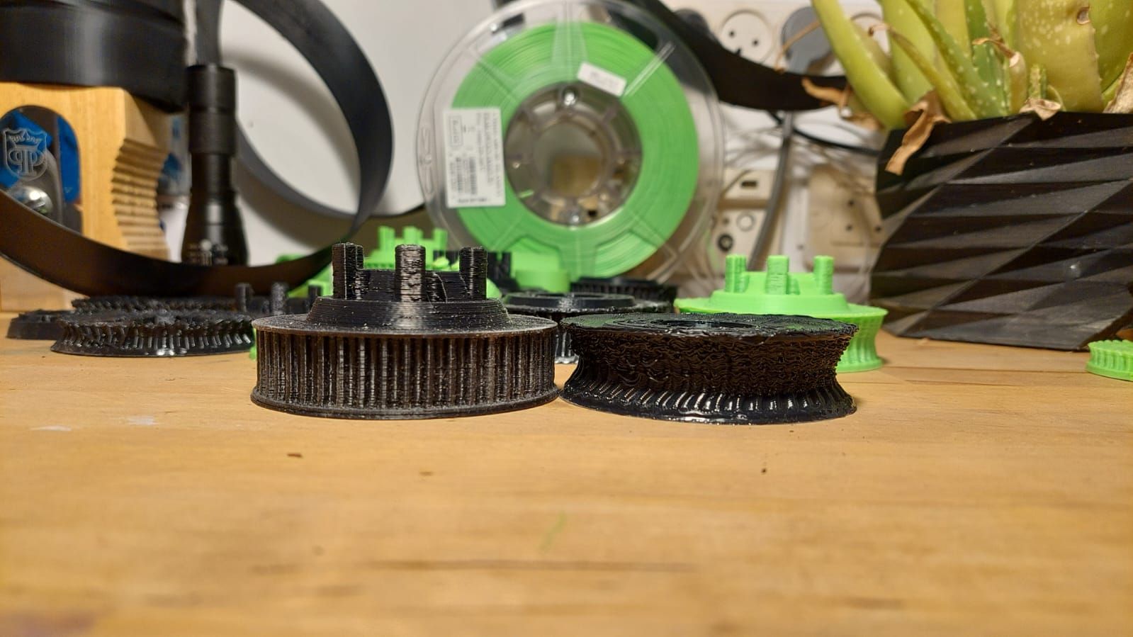
It would be great if you could send one last photo.
Maybe even a cog with the problem and a current cog next to it.
I would be interested in the end result, because the GIF doesn't show how well the print has become.
The top should also be visible.
Thanks !Thanks for all the tips, I'll definitely give them a try to see if I can improve my accuracy even more (or see how far off I am...)
First the side view (best I could do without a telecentric lens):
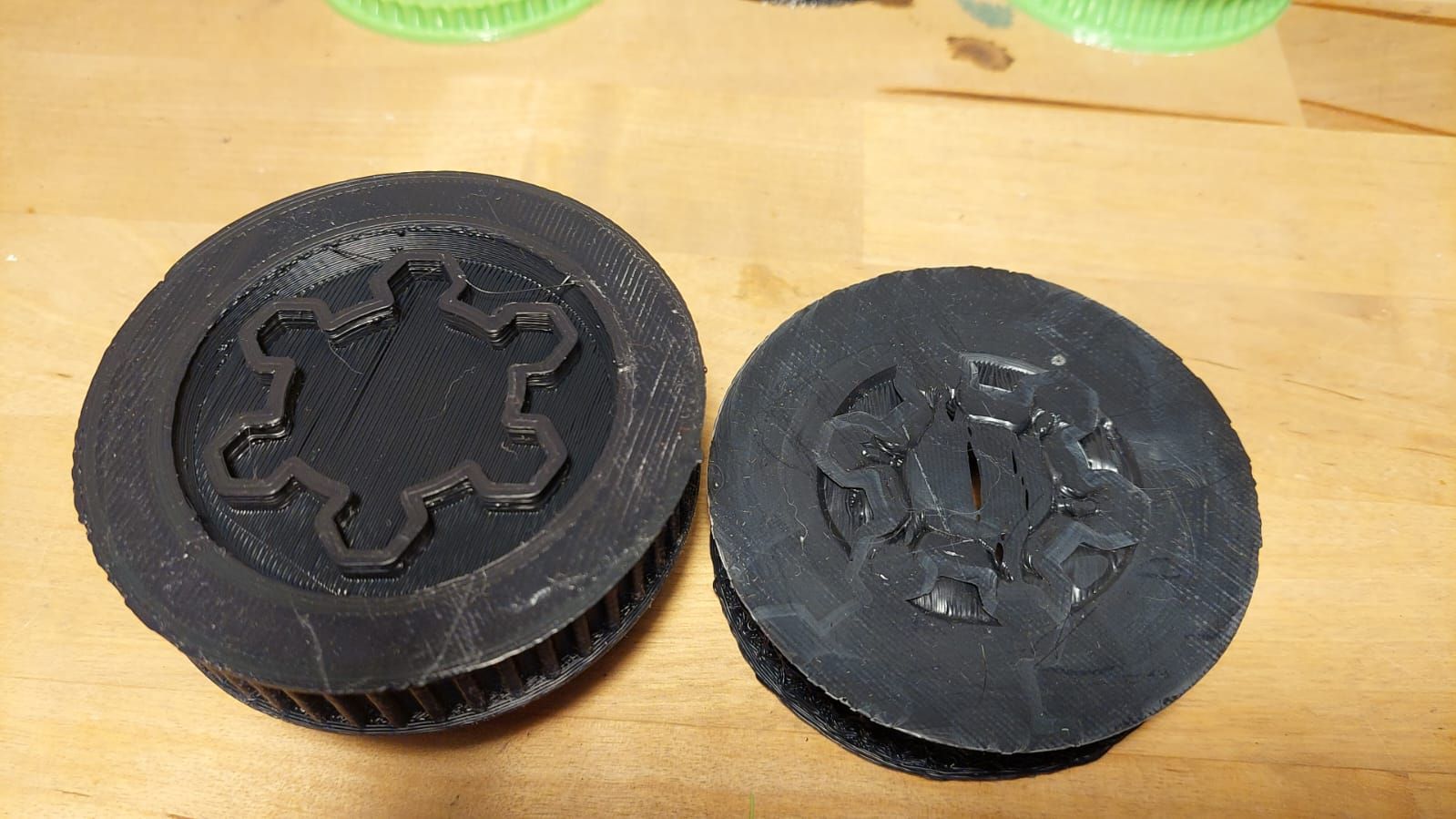
This shows the bottom cavity where the plastic collapsed into:
The next one is a GIF:
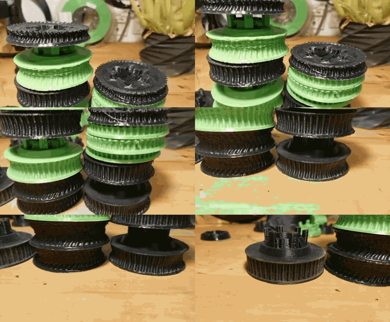
@o_lampe said in Mushrooming print - What could cause this?:
@leav
It still puzzles me, why it was able to collaps at 100% infill? But I'm glad you found a solution.The part designhas a central cavity, that gave the plastic a place to collapse into, that's my explanation for "where did the plastic go?".
@hackinistrator said in Mushrooming print - What could cause this?:
that's strange .
i have both esun ABS+ and polymaker ASA.
i use much higher bed temp , around 120-130c and never had this effect .
maybe your bed temp readings are way off .Definitely could be. I double checked with an IR thermometer and got ~5°c off the printer's reading (which is good for an unknown emissivity, I'd say...). Can't find my multimeter's thermocouple at the moment but I will double check it.
However I think there is a possibility that the readings are accurate and the cause for the different behavior might be:- High temperature inside the chamber (4 of the 6 walls are double aluminum panels with an air gap between them for better insulation, and the remaining doors are thick glass panels)
- Reflective aluminum walls bouncing the IR radiation from the oversized bed back to part to be absorbed.
-
Definitely could be. I double checked with an IR thermometer and got ~5°c off the printer's reading (which is good for an unknown emissivity, I'd say...). Can't find my multimeter's thermocouple at the moment but I will double check it.
However I think there is a possibility that the readings are accurate and the cause for the different behavior might be:- High temperature inside the chamber (4 of the 6 walls are double aluminum panels with an air gap between them for better insulation, and the remaining doors are thick glass panels)
- Reflective aluminum walls bouncing the IR radiation from the oversized bed back to part to be absorbed.
i suggest you measure the bed temp with a thermocouple + multimeter . some of the parts look completely melted (way higher then 100c) . my chamber temp is higher then 50c , its around 60 .at work i have stratasys printer thats prints abs with 90c chamber and nothing like that is happening .
your bed is huge , maybe the heat is uneven . also its worth checking the nozzle temp with external measurement -
@leav
If the area of a printed part is too small, the filament often gets too hot at this point and the nozzle underneath pushes/squeezes the layer outside.
You can see it in your photo where I drew the red circle.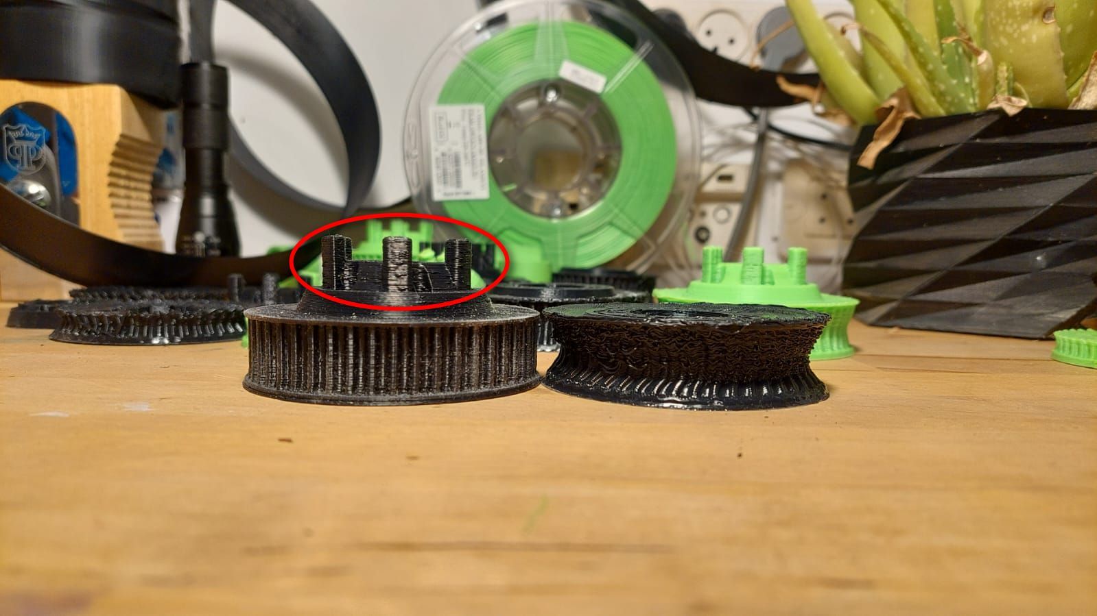
There is an extra setting in the slicer where you can enter the minimum print time for a layer, from when the fan should bring more cooling, the printer takes a short break or prints more slowly so that the filament can cool down there a little, making it firmer, before continuing to print.
This prevents such unsightly / deformed areas.
But you can also set the fan higher in the slicer using user-defined GCode from a certain layer, e.g. with the command M106 S127 (S0 = 0% / S255=100%).Example: With PrusaSlicer...
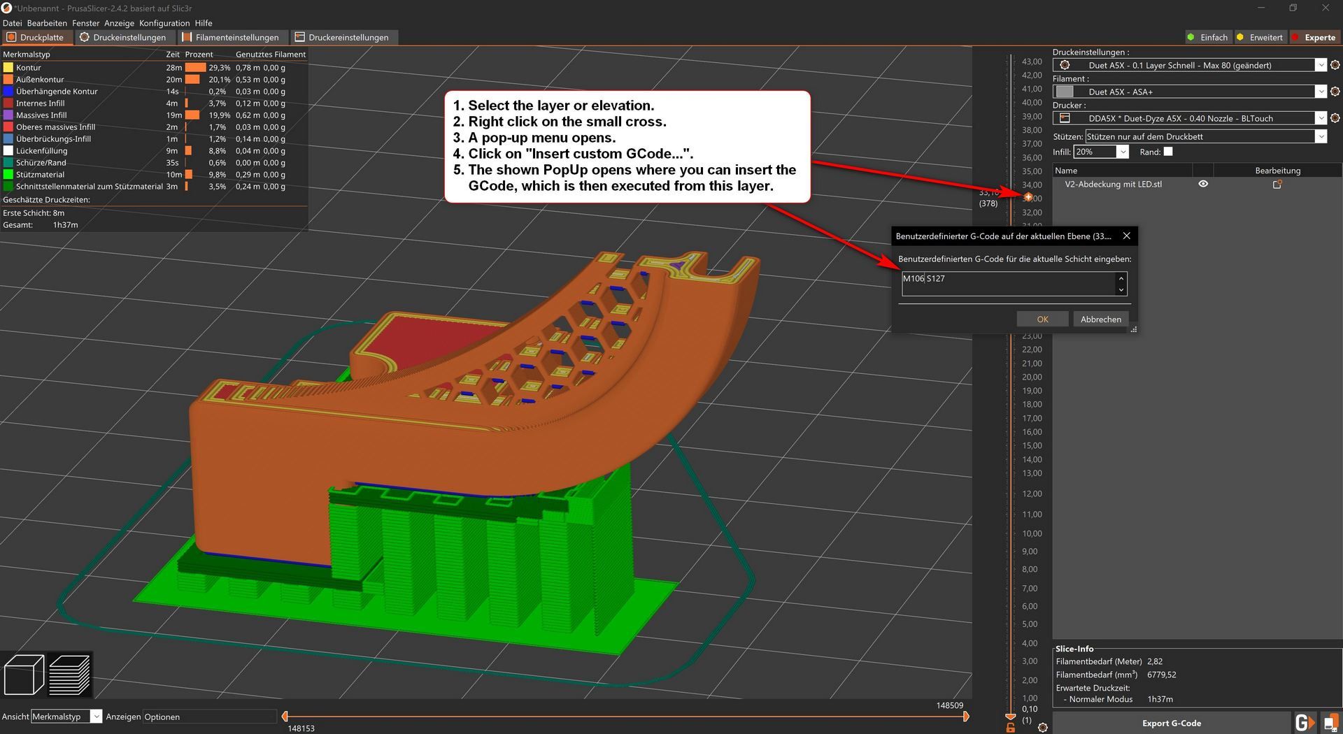
I also see that with the inner cavity where the filament flowed at 100% infill.
Maybe there was even a small suction effect where the air was heated by the pressure plate like a chimney and that's why the filament was always pulled inwards and there was never an outward flow direction.
At least I can't explain it any other way.Google Translate
--- Original Text ---Wenn die Fläche bei einem Druckteil zu klein wird, dann wird oft das Filament an dieser Stelle zu heiß und durch die Düse wird der darunter liegende Layer nach außen gedrückt / gequetscht.
So zu sehen auf Deinem Foto wo ich den roten Kreis eingezeichnet habe.
(Foto siehe oben)Es gibt dafür extra eine Einstellung im Slicer wo man die minimale Druckzeit für einen Layer eintragen kann, ab wann der Lüfter mehr Kühlung bringen soll, der Drucker eine kleine Pause einlegt oder langsamer druckt damit sich das Filament dort etwas abkühlen kann, somit fester wird, bevor weiter gedruckt wird.
Das verhindert solche unschönen / deformierten Stellen.
Man kann aber auch im Slicer per benutzerdefiniertem GCode ab einem bestimmten Layer, den Lüfter zB mit dem Befehl M106 S127 (S0 = 0% / S255=100%) höher stellen.Beispiel: Beim PrusaSlicer... (Screenshot siehe oben)
Das mit dem inneren Hohlraum wohin das Filament bei 100% Infill geflossen ist, sehe ich auch so.
Vielleicht entstand dort sogar ein kleiner Sogeffekt wo die Luft durch die Druckplatte wie ein Kamin erhitzt wurde und deswegen das Filament immer nach innen gezogen wurde und es nie die Fließrichtung nach außen hin gegeben hat.
Zumindest kann ich es mir anders nicht erklären. -
An IR thermometer cannot measure shiny surfaces as well.
It is best to stick a matt black adhesive tape on the printing plate and then measure the temperature there.PS:
What does the DWC show for temperatures at your HotEnd and your print bed if all parts are at room temperature?
Are the two values identical or at least very close to each other?P.P.S:
Is the thermistor from the heatbed cast directly into the heatmat or is it attached somewhere else?
If necessary, you should check whether it is still in contact with the heating bed.You should definitely check that first, because there is a very high risk that your printer will catch fire.
So there is danger to life !!! -
- IR Thermometer was pointed at the black FR4/G10 sheet (not the glass)
- At room temp, the readings are:
 Bed: 26.0°c
Hotend: 24.4°c
Chamber: 26.3°c
Multimeter probe on bed: 28°c
I suspected that my bed thermistor position was not giving a good reading, it was not exactly in the most sensible location.
Here you can see the temperature probe location (under the glass) and the multimeter's probe (I found it) placed on the bed in the center.
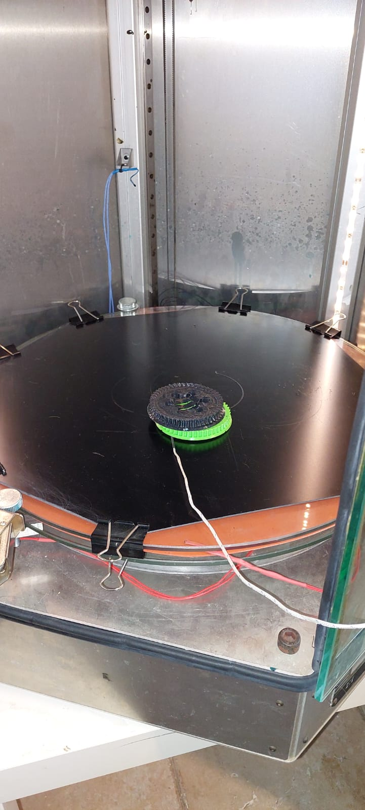
I later moved the bed probe (the one the printer uses) to the center of the bed and measured again (in the photo you see it on top of the glass, that's just to show where I placed it, in reality it is under the glass):
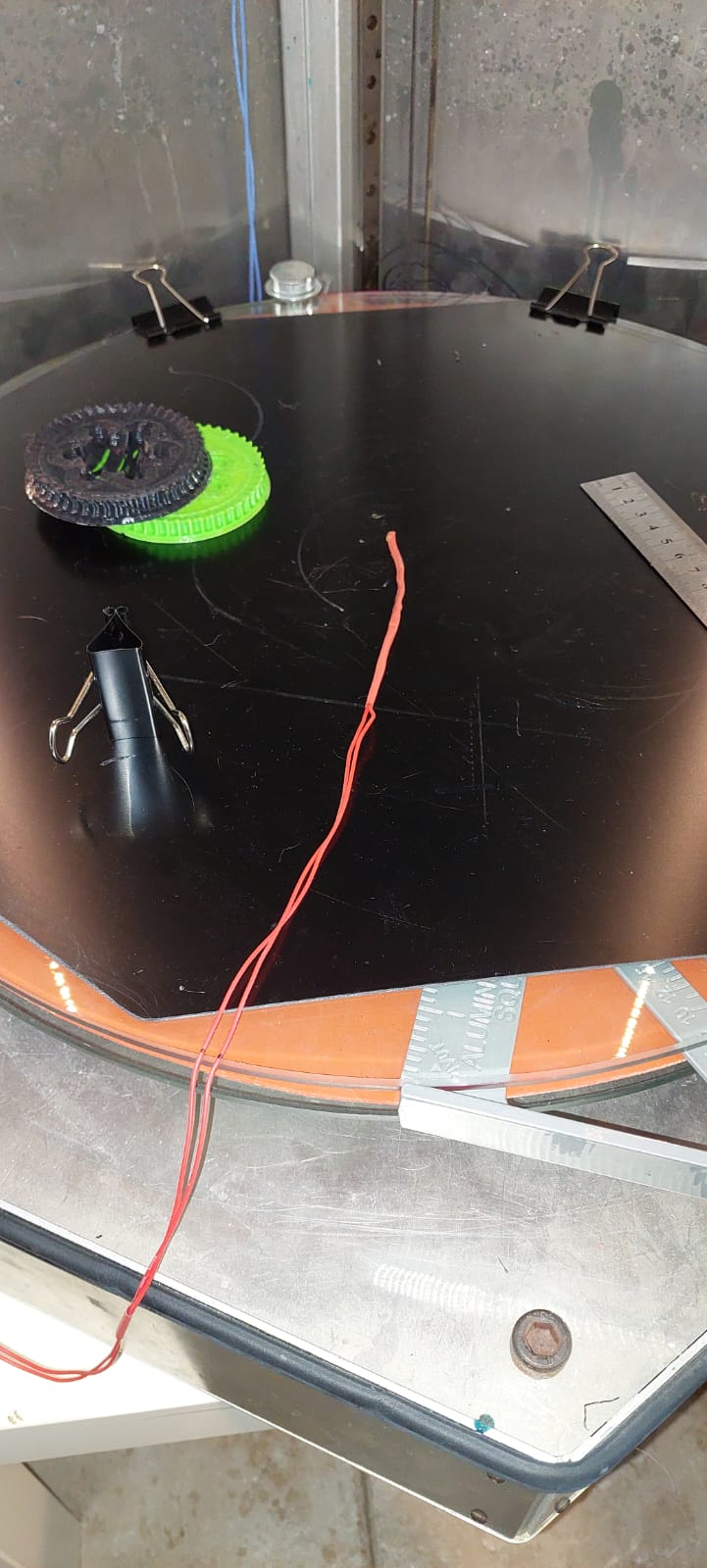
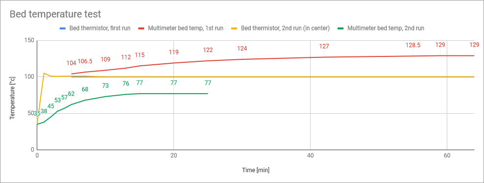
The results are quite dramatic:
- In both cases bed temp target is 100°c, and in both cases that temp is maintained on the thermistor very well (blue and yellow lines, blue is barely visible).
- The red line shows that when the probe was not in the correct location, the actual temperature in the center of the bed was much higher and reached ~130°c
- The green line shows that when the probe is placed in the center of the bed, the top of the bed reaches ~77°c
- This is both a large change between the two temperature measurements (~60°c) and in both cases a large error between the value that the controller sees and the actual temperature on top of the bed. I'll have to see how I can address this, possibly a different temperature probe location.
- To be clear, this means that when I thought my print bed temp was 110°c, it was closer to ~140°c, which could explain a few things.
-
@leav
Uijuijui.
After looking closely at this photo I guessed also an actual temperature around 140°C.
If something is flattened by heat and its own weight like the part on the right in the picture, then 110°C at ASA is not enough.I guess if you put matte black electrical tape on the glass plate, the temperature will be slightly higher than on the FR4 plate because of the possible air gap between FR4 and glass plate.
But this minimal difference is currently uninteresting.At the moment I don't even know how to adjust the temperature by command in config.g.
I think I've read something about this before!?
My brain sometimes has holes like Swiss cheese.
However, I would strongly advise against comparing the temperature of the surface with the Duet, since the temperature difference is very large.
I don't know exactly how your print bed is set up, how thick the glass plates are, etc.
But glass is generally not a good conductor of heat.
Because of this, I would be more inclined to worry about the difference between the set temperature and the actual temperature, or to make the bed more thermally conductive.An aluminum plate instead of glass would be the first step.
Insulate the heating mat from below against heat loss, I have a 10mm thick cork plate with me.
Cork is said to withstand temperatures slightly above 200°C.
I glued the heating mat to the 8mm aluminum plate with silicone adhesive that can withstand temperatures of up to 350°C.If I had to do it again today, I would put the print bed in a vacuum bag after gluing and leave it there for about 24 hours.
At that time I placed a heavy marble slab (base plate of a large parasol stand) on the printing bed.
Printbay's Blackprint magnet system is glued to the aluminum plate.
This magnetic plate can withstand heat up to 110°C.
The printing surface is a matte black FR4 plate with no overprints...all matte black.Printbay also has Blackprint magnetic systems for Delta printers, and you can get almost all sizes, I think he also cuts them to size, when I ordered my plate from him it was still a one-man operation.
For me, the maximum temperature difference between the display in the DWC and the measurement with an IR thermometer on the bed surface is about 2°C towards the edges (without housing) when I print at 60°C.
At 90°C the difference gets a bit higher, but I print 99% with temperatures from 60°C to 70°C, tending towards 60°C.Google Translate
--- Original Text ---Uijuijui.
Als ich mir dieses Foto genau angesehen hatte, vermutete ich auch eine tatsächliche Temperatur um die 140°C herum.
Wenn etwas durch Hitze und sein eigenes Gewicht so platt gedrückt wird wie das rechte Teil auf dem Bild ist, dann reichen 110°C bei ASA dazu nicht aus.Ich schätze wenn Du mattschwarzes Isolierband auf die Glasplatte klebst, ist die Temperatur etwas höher als auf der FR4 Platte, wegen dem möglichen Luftspalt zwischen FR4 und Glasplatte.
Aber dieser minimale Unterschied ist momentan uninteressant.Ich weiß im Moment gar nicht wie man die Temperatur per Befehl in config.g justiert.
Ich glaube ich habe darüber schon mal etwas gelesen !?
Mein Hirn hat manchmal Löcher wie ein schweizer Käse.
Ich würde aber dringend davon abraten die Temperatur der Oberfläche mit dem Duet abzugleichen, da der Temperaturunterschied doch sehr groß ist.
Ich weiß nicht wie Dein Druckbett genau aufgebaut ist, wie dick die Glasplatten sind etc pp.
Aber Glas ist allgemein kein guter Wärmeleiter.
Deswegen würde ich eher dazu tendieren sich mit dem Unterschied der eingestellten Temperatur und der tatsächlichen Temperatur zu angergieren oder das Bett Wärmeleitfähiger zu machen.Eine Aluplatte anstelle von Glas wäre der erste Schritt.
Die Heizmatte nach unten hin vor Wärmeverlust isolieren, ich habe bei mir eine 10mm starke Platte aus Kork.
Kork soll Temperaturen etwas über 200°C standhalten.
Die Heizmatte habe ich mit Silikonkleber der bis zu 350°C aushält, an die 8mm Aluplatte geklebt.Würde ich es heute nochmal machen müssen, würde ich das Druckbett nach dem kleben in ein Vakuumbeutel stecken und es dort für etwa 24 Stunden belassen.
Ich habe damals eine schwere Marmorplatte (Grundplatte eines großen Sonnenschirmständers) auf das Druckbett gestellt.
Auf der Aluplatte ist das Blackprint-Magnetsystem von Printbay geklebt.
Diese Magnetplatte hält Hitze bis 115°C stand.
Die Druckoberfläche ist eine mattschwarze FR4 Platte ohne Aufdrucke... alles mattschwarz.Printbay hat auch Blackprint Magnetsysteme für Delta Drucker, und man bekommt fast alle Größen, ich glaube er schneidet auch zu, als ich meine Platte bei ihm bestellte war es noch ein Einmann-Betrieb.
Bei mir ist der maximale Temperaturunterschied zwischen Anzeige im DWC und der Messung mit einem IR-Thermometer auf der Bettoberfläche etwa 2°C zu den Rändern hin (Ohne Umhausung) wenn ich mit 60°C drucke.
Bei 90°C wird der Unterschied etwas höher, aber ich drucke zu 99% mit Temperaturen von 60°C bis 70°C, mit der Tendenz zu 60°C. -
 undefined Norder referenced this topic
-
 undefined Norder referenced this topic
-
 undefined Norder referenced this topic
-
 undefined Norder referenced this topic
-
 undefined Norder referenced this topic
-
 undefined Norder referenced this topic