Toolboard 1LC "Port must be on mainboard"
-
Almost finished setting up my new Duet 3 Toolboard 1LC, but having trouble . i have everything wired and most peripherals working, but I get "Port must be on mainboard" error. Ive attached a wiring picture, my config.g, and the output of M98 P"config.g" and M122 B121:
M98 P"config.g"
9/30/2022, 3:33:11 PM 	Warning: Heater 0 predicted maximum temperature at full power is 328°C
Error: Port must be on main board
Warning: the height map was loaded when the current Z=0 datum was not determined by probing. This may result in a height offset.
Warning: Macro file config-override.g not found
M122 B121
9/30/2022, 3:34:16 PM 	M122 B121
Diagnostics for board 121:
Duet TOOL1LC rev 1.1 or later firmware version 3.4.2 (2022-09-13 15:06:56)
Bootloader ID: SAMC21 bootloader version 2.3 (2021-01-26b1)
All averaging filters OK
Never used RAM 2592, free system stack 62 words
Tasks: Move(notifyWait,0.0%,153) HEAT(notifyWait,0.2%,115) CanAsync(notifyWait,0.0%,61) CanRecv(notifyWait,0.0%,76) CanClock(notifyWait,0.0%,65) ACCEL(notifyWait,0.0%,61) TMC(delaying,3.0%,57) MAIN(running,91.8%,349) IDLE(ready,0.0%,26) AIN(delaying,4.9%,142), total 100.0%
Last reset 00:04:02 ago, cause: power up
Last software reset data not available
Driver 0: pos 0, 80.0 steps/mm,standstill, SG min 0, read errors 0, write errors 0, ifcnt 11, reads 55790, writes 11, timeouts 0, DMA errors 0, CC errors 0, steps req 0 done 0
Moves scheduled 0, completed 0, in progress 0, hiccups 0, step errors 0, maxPrep 0, maxOverdue 0, maxInc 0, mcErrs 0, gcmErrs 0
Peak sync jitter -3/8, peak Rx sync delay 207, resyncs 0/0, no step interrupt scheduled
VIN voltage: min 24.0, current 24.1, max 24.1
MCU temperature: min 23.4C, current 33.5C, max 33.5C
Last sensors broadcast 0x00000002 found 1 209 ticks ago, 0 ordering errs, loop time 0
CAN messages queued 4938, send timeouts 0, received 2248, lost 0, free buffers 37, min 37, error reg 0
dup 0, oos 0/0/0/0, bm 0, wbm 0, rxMotionDelay 0
Accelerometer: LIS3DH, status: 00
I2C bus errors 0, naks 3, other errors 0
Config.g
; General preferences
G90                                     ; send absolute coordinates...
M83                                     ; ...but relative extruder moves
M550 P"V-Core3"                         ; set printer name
M669 K1                                 ; CoreXY
G21                                     ; Set Units to Millimeters

; Network
M552 S2                                 ; enable network
M586 P0 S1                              ; enable HTTP
M586 P1 S0                              ; disable FTP
M586 P2 S0                              ; disable Telnet

G4 S2 ; wait for expansion boards to start

; Drives
M569 P0.0 S0 D2	                        ; Left Z physical drive 0.0 goes forwards
M569 P0.1 S0 D2                         ; Rear Z physical drive 0.1 goes forwards
M569 P0.2 S0 D2                            ; Right Z physical drive 0.2 goes forwards
M569 P0.3 S1 D2                            ; Right physical drive 0.3 goes forwards
M569 P0.4 S1 D2                            ; Left physical drive 0.4 goes forwards
M569 P121.0 S1 D2                            ; Extruder physical drive 0.5 goes forwards
M584 X0.4 Y0.3 Z0.0:0.1:0.2 E121.0        ; set drive mapping
M350 X16 Y16 Z16 E16 I1                 ; configure microstepping with interpolation

M92 X80.00 Y80.00 Z800.00 E400               ; set steps per mm
M906 X1400 Y1400 Z1400 E600 I30              ; set motor currents (mA) and motor idle factor in per cent -- safe for Duet 3 mini 5+
M84 S30                                 ; Set idle timeout

M566 X1000.00 Y1000.00 Z6.00 E120.00 P1          ; set maximum instantaneous speed changes (mm/min)
M203 X30000.00 Y30000.00 Z1000.00 E3600.00     ; set maximum speeds (mm/min)
M201 X12000.00 Y12000.00 Z100.00 E3600.00        ; set accelerations (mm/s^2)

; Axis Limits
M208 X0 Y0 Z0 S1                               ; set axis minima
M208 X310 Y310 Z300 S0                         ; set axis maxima

; Endstops
M574 X1 S1 P"121.io2.in"                           ; configure active high endstops
M574 Y2 S1 P"io1.in"                           ; configure active high endstops

M671 X-4.5:150:304.5 Y-4.52:305:-4.52 S5       ; define positions of Z leadscrews or bed levelling screws
M557 X20:280 Y20:280 P5                        ; define 5x5 mesh grid

; Heaters
M308 S0 P"temp0" Y"thermistor" T100000 B3950 A"Bed"    ; configure sensor 0 as thermistor on pin temp0
M950 H0 C"out0" T0 Q10												; Define Heater0 as the heated bed, bind to Sensor0
M140 H0 P0															; Define Heated Bed
M307 H0 A303.1 C356.7 D1.4 S1.00 V24.0 B0
;M307 H0 R0.860 C439.9 D11.80 S1.00 B0							; PID Tuning for Heater0, Heated Bed (45C)
M143 H0 S110														; Set temperature limit for Heater0 to 120C

M308 S1 P"121.temp0" Y"thermistor" T100000 B4725 C7.060000e-8 A"Hotend"
M950 H1 C"121.out0" T1 Q100													; Define Heater1 as Extruder0 heater, bind to Sensor1
M307 H1 R3.075 K0.558:0.000 D4.86 E1.35 S1.00 B0 V24.0
;M307 H1 R2.794 C119.4:105.8 D3.09 S1.00 V24.1 B0					; PID Tuning for Heater1, Extruder0 (200C)
;M307 H1 A751.5 C196.6 D4.7 S1.00 V23.9 B0
M143 H1 S285														; Set temperature limit for heater 1 to 285C
;M308 S2 P"temp2" Y"thermistor" A"Chamber" T100000 B4725 C7.060000e-8; Define Sensor2 as Chamber temperature (Semitec 104GT2)
M308 S3 Y"mcu-temp" A"MCU"											; Define Sensor3 as the integrated MCU temperature sensor
M308 S4 Y"drivers" A"TMC Drivers"									; Define Sensor4 as the TMC overheat sensor

; Fans
M308 S2 Y"drivers" A"4028 Power"    								; configure sensor 0 as thermistor on pin temp0
M950 H2 C"!out2" T2 Q10												; Define Heater2 as the 4028 fan power, bind to Sensor2
M143 H2 P2 S200
;M307 H2 I1 S1
;M106 P2 C"4028 Power" S0 H-1										; 4028 power using spare heater

;M950 F0 C"121.out1" Q500                   							; create fan 0 on pin out4 and set its frequency
M950 F0 C"!121.out1+out1.tach" Q25000
M106 P0 C"Layer Fan" S0 L0.0 X1.0 H-1
;M106 P0 C"Layer Fan" S0 H-1            							; set fan 0 name and value. Thermostatic control is turned off

;M950 F1 C"out3" Q500                   ; create fan 1 on pin out3 and set its frequency
M950 F1 C"121.out2+out2.tach" Q500 				; Fan 1 uses out3, and using out3.tach as a tacho input
M106 P1 C"Hotend Fan" S0 H1 T45        ; set fan 1 name and value. Thermostatic control turned on for Hotend

;M950 F1 C"out5" Q500                   ; create fan 1 on pin out5 and set its frequency
;M106 P1 C"Hotend Fan" S0 H1 T45        ; set fan 1 name and value. Thermostatic control turned on for Hotend

; Tools
M563 P1 D0 H1 F0 S"Mosquito Magnum"           										; define tool 0
G10 P1 X0 Y0 Z0            ; set tool 0 axis offsets
G10 P1 R190 S0               ; set initial tool 0 active 60C and standby temperatures to 0C

;M563 P0 H0 F0 S"Keenevo 600W Bed"
;G10 P0 X0 Y0 Z0
;G10 P0 R50 S0

; EVA 2 / BMG / E3D V6

;M92 E400          ; set extruder steps per mm, 0.9 angle/step (LDO Pancake)
;M906 E800         ; set extruder motor current (mA) and idle factor in per cent

;M308 S1 P"temp1" Y"thermistor" T100000 B4725 C7.060000e-8 A"Hotend"
;; Run Heater PID Tune!!
;; M307 H1 A751.5 C196.6 D4.7 S1.00 V23.9 B0

; Z-Probe
;; Inductive Probe
;M558 P5 C"io3.in" H5 F400 T5000       ; set Z probe type to unmodulated and the dive height + speeds
M558 P8 C"121.io0.in" H5 F400 T5000       ; set Z probe type to unmodulated and the dive height + speeds
G31 P1000 X-28 Y-15 Z0.79               ; set Z probe trigger value, offset and trigger height, more Z means closer to the bed
;G31 P500 X-30 Y-15 Z0

;; BLTouch
; M950 S0 C"io7.out"                     ; Create a servo pin on io7
; M558 P9 C"io7.in" H5 F240 T10800 A5    ; set Z probe type to unmodulated and the dive height + speeds
; G31 P25 X-28.00 Y-13.00 Z0.78          ; set Z probe trigger value, offset and trigger height, more Z means closer to the bed

;Accelerometer
M955 P0 C"121.io2.out+121.io2.in" I54

;Input Shaper
;M593 P"zvd" F41.9		; for 10k acceleration
;M593 P"mzv" F41.9		; for 15k acceleration

; Select default tool
T0

;Filament Sensor0
M591 D0 P3 C"121.io1.in" S1
M591 D0 L24

;PanelDue 5i
M575 P1 S1 B57600

; Custom settings are not configured
G29 S1
M572 D0 S0.10; set Pressure Advance K-factor
M501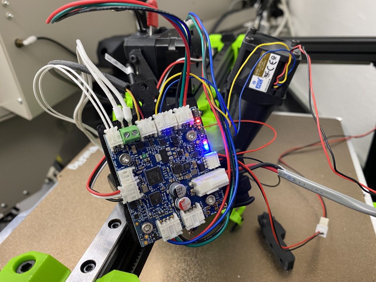
-
@rogerpodacter said in Toolboard 1LC "Port must be on mainboard":
M955 P0 C"121.io2.out+121.io2.in" I54
That is not how you configure the accelerometer built into the toolboard. From the docs:
To use an accelerometer on a CAN-connected expansion board, use the form Pboard-address.device-number for example P22.0.So in your case:
M955 P221.0 I54Should hopefully work. See: https://docs.duet3d.com/User_manual/Reference/Gcodes#notes-144
-
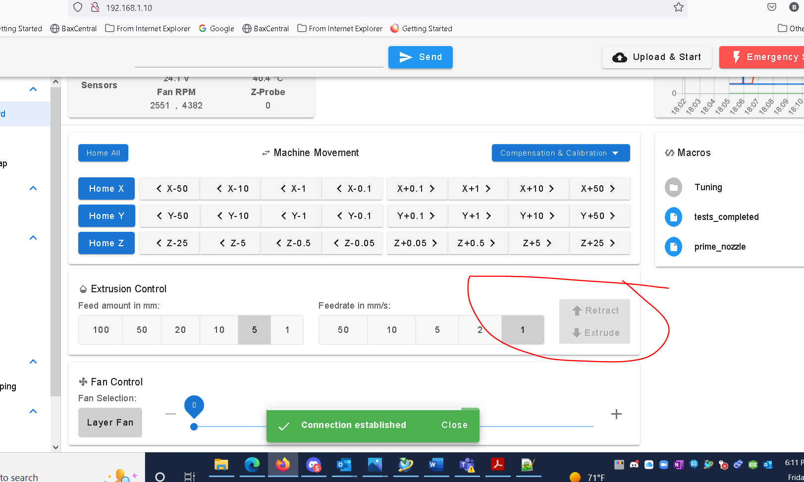
@gloomyandy Thanks, that removed that error but gave another one. but i wasnt clear in my original post. My extruder is the issue which does not work. When i bring up to temperature, i cannot extrude anything as the buttons are not active. Screenshot is below.
Also, the new error is now this:
EDIT: nevermind i fixed the accelerometer error by using M955 P121.0 I54. but i still have no extruder working.M98 P"config.g"
9/30/2022, 6:05:59 PM 	Error: Response timeout: CAN addr 93, req type 6034, RID=42
Warning: the height map was loaded when the current Z=0 datum was not determined by probing. This may result in a height offset.
Warning: Macro file config-override.g not found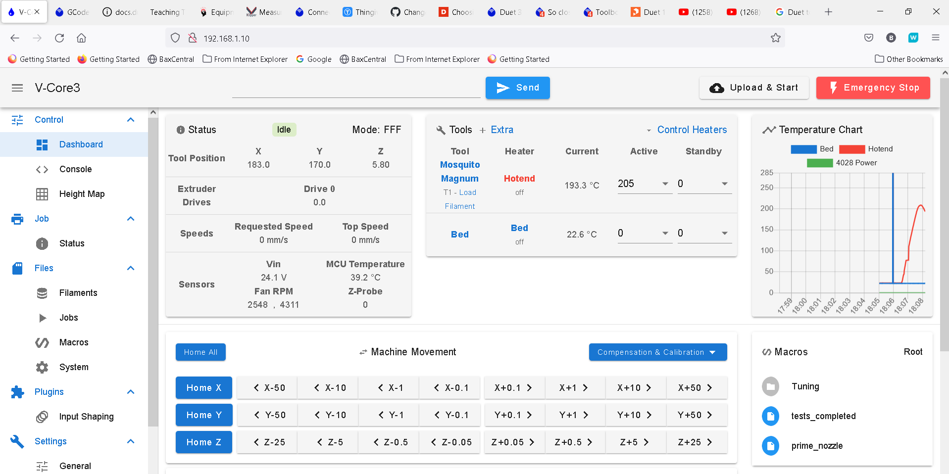
-
EDIT: deleted my config.g backup and the issue resolved itself. i've experienced that on a few occasions. i make a change and it does not take effect even after a reboot. one or 2 times later it finally takes hold.
@rogerpodacter now its even stranger. i ran a print job, and the extruder ran backwards, even though my wiring is identical to when it was connected to the mainboard.
M569 P121.0.0 S1 D2
So then i switched to this, and it still ran backwards.
M569 P121.0.0 S0 D2Either one of those run backwards, how is that possible?
-
@rogerpodacter is the toolboard running the right firmware?
Post the output ofM115andM115 B121 -
@rogerpodacter most likely the main board is starting up and sending commands to the tool board before the tool board has finished starting up.
-
Check that in config.g you have a delay command such as G4 S2 before the first command that refers to board 121 (which is probably your M569 command).
-
Also use M122 B121 to check which bootloader version the tool board has.
-