Delta bed leveling issues
-
I've finally determined I need to ask some experienced eyes to help me out! Any and all assistance is greatly appreciated!
I have a Rostock v3 max that I've extensively upgraded. One of my interns at a previous company assembled this printer (not always a recipe for complete success!
") ). It has never once in its life worked quite right. Over the last year (while working at home sitting through Teams calls!), I tore it down and did a bunch of upgrades, I found a couple of intern-induced issues with the build, but nothing I've fixed so far has gotten me to a properly performing printer.
). It has never once in its life worked quite right. Over the last year (while working at home sitting through Teams calls!), I tore it down and did a bunch of upgrades, I found a couple of intern-induced issues with the build, but nothing I've fixed so far has gotten me to a properly performing printer.The hardware setup is now as follows:
- a v3 Max base,
- original glass bed with a PEI sheet stuck on it,
- 0.9-degree steppers all around with the 16 tooth pulleys,
- the newer SE300 effector with strain-based touch probing,
- carbon fiber arms,
- Duet 3 MB6HC (MB6HC),
Firmware: RepRapFirmware for Duet 3 MB6HC 3.4.1 (2022-06-01)
I've tried both 6-point and 8-point (6-point plus bed angle variety) calibration without seeing much difference between them. When I do a bed surface scan with the touch probe, the result has a pattern that suggests a systemic alignment issue; I just can't put my finger on exactly what's wrong.
At this point, the only thing I have not messed with too much is the actual tower assembly. My assumption has been since the tower positions are set by semi-precision (injection molded and laser cut) parts, they should be pretty accurate.
I did check the towers for warp with a machinist's straight edge, and they all seem quite good.I've attached the following:
config.g
config-override.g
bed.g
homedelta.g
heightmap.csvPhoto of the first layer of a bed size test piece show how the outer areas have very different coverage than the center.
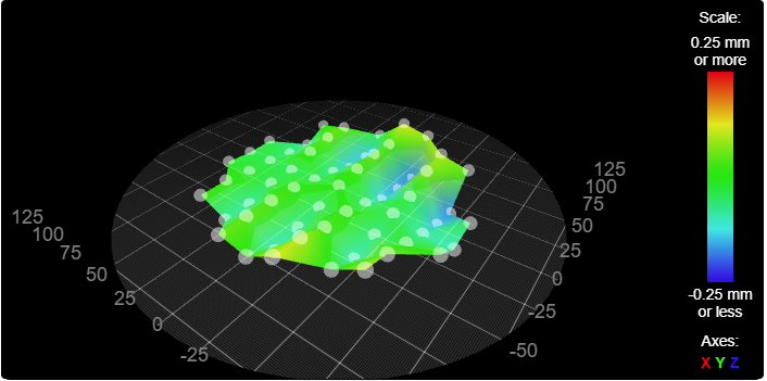
Screenshot of the 3D render of the bed height map.

heightmap.csv
config-override.g
config.g
bed.g
homedelta.gAny advice would be great. I can think of a couple of next steps, but they are getting to be more and more effort, so I figured I would see if this symptom was something someone else was familiar with!
-
@rndmnmbr
I've seen this wave pattern that the heightmap shows before.
I'll link you to the thread with the problem here.The problem was due to the eccentric screws of the print head, which was always tilted back and forth due to the tension of the toothed belt, thus creating the wave pattern on the MBL.
So check all moving parts for play or loose screws.
Google Translate
-- Original Text --Dieses Wellenmuster was die heightmap anzeigt, habe ich schon einmal gesehen.
Ich verlinke Dir hier mal den Thread mit dem Problem.Das Problem lag an den Exenterschrauben des Druckkopfes, der durch den Zug des Zahnriemens immer hin und her gekippt wurde und so das Wellenmuster beim MBL entstand.
Kontrolliere also alle beweglichen Teile auf Spiel oder lockere Schrauben.
-
@rndmnmbr I had the exact same issue on my delta with the smart effector, which for me the cause was backlash in the mechanics. I fixed it by changing all screw-nuts holding the arms and effector to nyloc to avoid them being able to unscrew themselves. I'm not sure how the Rostock effector and arms are attached but it might be something worth trying out
-
@rndmnmbr that pattern is caused by backlash in the movement as @Snimax reported. What's happening is that when you command the nozzle to a particular point, the height that it ends up at depends on the direction that you approached the point from. For example, if the point is at X=+100 then backlash will cause the actual height to change depending on whether you approached it from a higher or a lower X position. At X=-100 the effect is reversed. The pattern you see is caused because when RRF does grid probing, it probes the first row in the +X direction, then the second row in the -X direction, then the third row in the +X direction u.s.w.
So I suspect that either the joints or the linear rails in your machine are sticky, or the belts are loose, or you have the stepper motor current set much too low, or you have a slightly loose pulley, or some part of the mechanics isn't tightened up as was the case for @Snimax.
-
Thanks so much for the input! It's really appreciated.
I'll look at those factors and see what comes out of it.I've got a lot of hands on with CNC mills, so I'm pretty familiar with backlash. @dc42 what you are saying makes a lot of sense - I just never really wrapped my head around what backlash looks like on a delta!
-
Oh man, I've chased that delta printer backlash down to ~0.05mm on my rostock metal max. I stopped chasing it after it got that low since it gets harder to identify the source the smaller the backlash gets.
-
@lord-binky What kind of sources did you find?
I went ahead and yanked off the arms and effector to start with, and put an upside down dial indicator on the bed. I've been using that to examine unloaded backlash at each tower.
I found one tower "skate" that isn't quite right. It's got a "click" and some displacement when I put lateral force on it. I suspect this may be the root of at least some of my issue. I need to troubleshoot this and then keep going.
I'm thinking I'll stick some mass on each skate and then recheck to see what the loaded numbers look like. On a mill, loaded is frequently better than unloaded ...