2 Kinematics / 1 Printer - filament arm
-
hello all together,
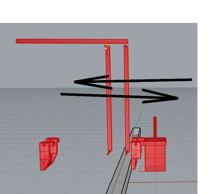
I´m working on a arm which helps to hold the filament hose and cables right above the tool.
It´s a very hugh tool changer.My idea is to have an 2 axis arm which has a different kinematic compared to my cartesian style printer and it may be activated by macros.
I know everything about macros, sadly nothing about meta commands, yet ( I wanna change this).My biggest question is how to install an 2 axis arm configuration.
May somebody can give me some Information which will help to implement a good kinematic.
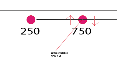
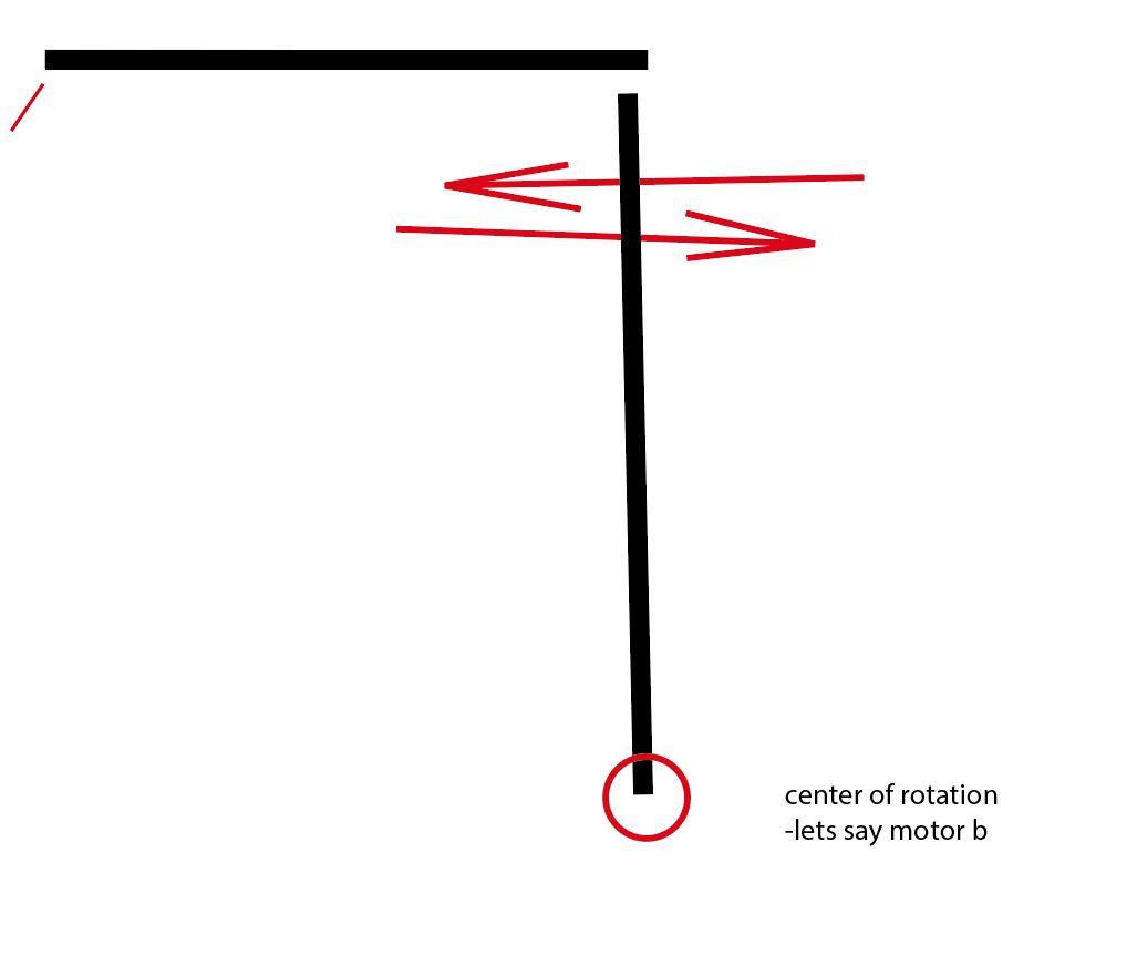
Every arm should have a base turning point (see pictures) and and a motor to push the the axis forwards and backwards.
I hope my pictures will help to understand it.
I´m working with a always updated Duet 3 6hc and SBC.Thanks to all who is helping in this great and helpful forum
Richard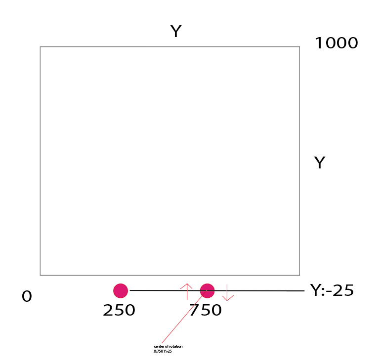
-
@IndeX4D are you planning on synchronization of the arm movement with the main machine kinematics during printing? Also why did you choose an arm for this purpose and not a stacked gantry design like @deckingman has?
-
@T3P3Tony
yes I wanna synchronize the arm. It should hold heavy wires and different filament hose. It´s a very big machine with high speed ambitions.I wanna use the arm because it´s cheap to build, I have some things already here to build and it´s saving space because the roof is not high enough for the printer.
Where can I finf this gantry thing from @deckingman?
Thanks
-
@IndeX4D
I found deckingmans machine.
This is not an option for me because of the size.
I´m building insutrail size tool changer and we have been thinking a lot about this system.But it´s really hard to have support for such a project in terms of g codes or meta commands.
Also when I could make a description for all other users.... ;/ -
@IndeX4D how rigid would the connection between the arm and the tool be? Does it need to be exactly in sync (in which case I think it would need to be in the same kinematics), or does it just need to be generally in the same area of the printer?
Another option, at least for initial R&D is define the arm as two more axes and then directly control the motor positions with gcode as part of the movement commands of the main printer. That would require custom gcode generation in a slicer or post processor.
-
@IndeX4D said in 2 Kinematics / 1 Printer - filament arm:
@IndeX4D
I found deckingmans machine.
This is not an option for me because of the size.
I´m building insutrail size tool changer and we have been thinking a lot about this system.But it´s really hard to have support for such a project in terms of g codes or meta commands......................
As I saw my name being mentioned, I thought I'd just jump in here. So, my machine has two XY axes. The first XY carries the (heavy) multi-input hot end. The second (UV) carries the 6 extruders which feed that hot end. So the application is similar in concept to what I believe to be your use case.
Size wise, my machine has outer dimensions of 600mm x 600mm in X and Y but it could be scaled up to any dimensions. If you can build an XY gantry large enough for your needs, then you can almost certainly build a duplicate above it. The distance between the two gantries can be large or small - there are no restrictions which wouldn't also apply to any other "arm".
With regard to gcodes and meta commands, there are two options that I use. The first is the simplest in that you map the UV motors to the XY axes. So any G1 Xnn Ynn command will move both gantries in synchronisation with each other. You can use standard gcode files from any slicer and you can home the gantries individually by splitting the motors to individual XYU and V axes, then combine them at the end of homing. So no special or gcode commands required, nor any custom kinematics (CoreXYUV is "natively" supported). The second option is to leave the axes as individual XYU and V axes but then you have to post process the sliced gcode file to generate the U and V moves. That is what I do because I prefer the UV gantry to follow the XY gantry but within an allowable tolerance. It's more complicated but allows me to (for example) position the UV gantry in the centre of a circle or other small feature where it will remain stationary while the hot end on the XY axis carries out the small moves necessary to print that feature.
There is a third option but it's not so elegant. That is not have your arm or gantry actively driven with separate motors but rather to provide a mechanical linkage to the tool carriage so that it gets passively "dragged around".
-
yes I wanna synchronize the arm movement with the machine kinematics.
I choosed this method because I can easily install it with a few printed parts and motors which I have here.
I also don´t need a accurate movement. The end of the arm will be a bit flexible. It´s mainly to keep the load away from printhead and safe space to the roof.Thanks
-
@deckingman
thanks for your detailed reply.I think to say it short. I would like to have an lightweigth arm for each tool, which follows the movement of the printhead and carrys cables and filament hose, but the end (near the printhead) is flexibel. One motor turns the arm (Lets say center of rotation is at x250 Y-25) , one motor stretches the arm like a littel crane.
I think for my use case I prefer the option with the CoreXYUV, but I´m not sure how to tell the printer the exact movement, because the move is not linear like the other axis....@deckingman
I saw that your heavy gantry is not doing small moves, because it´s also flexibel between the the gantrys. May I would like to know or learn more about it and the post processing work. That is very interesting for me. I think I would prefer this way also when it´s more complicated.
May you can give me a small overview about the post processing etc.
That would be awesome!! or something to read and learn by myself.or in other words... I think it´s nice to have your movement system but with an 2 motors arm instead of a second gantry.
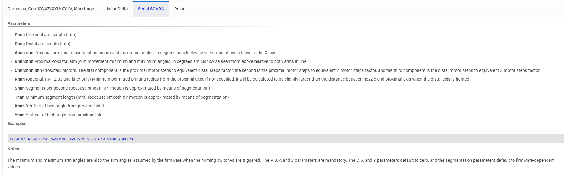
EDIT: I found this kinematic and I wonder If I can coose this one just for the arm(s), but in my style with a vertical joint for the proximal-to-distal joint/motor. Or bad idea?
Thanks a lot
Richard -
I'm not entirely sure, but AFAIK it's not possible to mix cartesian and SCARA kinematics on one controller.
But you might have a chance with a special SBC setup, where the SBC controls two independent Duets: one for cartesian, the other for all the SCARA stuff.
The SBC would run a "gcode-splitter" which sends axis commands for XYZ to the cartesian controller and the other axes to the other controller.
Not sure if thats just a wet dream, @chrishamm ? -
@IndeX4D said in 2 Kinematics / 1 Printer - filament arm:
@deckingman
thanks for your detailed reply.I think to say it short. I would like to have an lightweigth arm for each tool, which follows the movement of the printhead and carrys cables and filament hose, but the end (near the printhead) is flexibel.
If all it's carrying is the cables and filament, your could do what I do with my third gantry which I haven't mentioned before. This is my AB gantry which used to be driven and which used to do the opposite of the XY and UV gantries and acted as a load balancing/force cancelling gantry to counteract the effect of throwing 3Kgs of mass around. Since I changed my control boards, I have removed the motors and belts from this gantry and mounted the control board onto it. The gantry is passively "dragged" around by the cables connecting the control board to the extruders and hot end. Because of the low mass, it works well - of course I had to make sure that I had strain relief to prevent excessing strain on the connector. No special kinematics or configuration required - custom or otherwise.
@deckingman
I saw that your heavy gantry is not doing small moves, because it´s also flexibel between the the gantrys. May I would like to know or learn more about it and the post processing work. That is very interesting for me. I think I would prefer this way also when it´s more complicated.
May you can give me a small overview about the post processing etc.
That would be awesome!! or something to read and learn by myself.Well I'm not very good at writing code - I'm a 69 year old retired mechanical engineer with no formal training in writing code. But I've uploaded my python script to me google drive so you can download it from here
https://drive.google.com/file/d/1ORiCAP4LhMWPwDH45SS12oqpDNxHSFfP/view?usp=sharingI can't tell you much about it because I wrote it a long time ago, but it's fairly well annotated. It isn't pretty and I'm sure that someone who knew how to write code better than me, would make a more elegant solution. But it gets the job done reasonably well.
-
-
https://forum.duet3d.com/topic/17479/assign-axes-to-kinematic-multiple-kinematics
How about this threads..... Can´t I just install an arm?How about the CoreXYUV. I could not find a solution to tell the printer the turning point or base turning point of the U and V and how to define those. I mean it´s a non linear move and I ask again: Is this possible with this kinematic?
How to define a 2 axis arm? @T3P3Tony
I´m sorry but I have been thinking a lot about my filament arm. I just need software support and not 10 more physical ideas......like I also had many ideas. I tried everything without a motor on the arm by moving it by hand. It´s physycally working...
I mean it should be working to have an arm which follows the printhead, I think.
Thanks a lot
-
@IndeX4D said in 2 Kinematics / 1 Printer - filament arm:
I just need software support and not 10 more physical ideas......like I also had many ideas. I tried everything without a motor on the arm by moving it by hand. It´s physycally working...
The reason i mentioned other options for this is they already exist as kinematics in firmware. What you need is a new, custom, kinematics class to achieve your requirements and currently cant use multiple kinematics at the same time. That is unless @JoergS5 's work would generalise as far as this.
In the mean time you could potentially process the gcode so the commands for the arm movement were included in the same command as the main printer command:
e.g.
G1 Xnn Ynn Znn Ann BnnWhere the Ann and Bnn were the absolute rotations required to keep the end of the arm where you needed it for the XY positions of the main printer. That is basically doing the kinematics for this part of the system outside of the firmware.
-
@IndeX4D said in 2 Kinematics / 1 Printer - filament arm:
How about the CoreXYUV. I could not find a solution to tell the printer the turning point or base turning point of the U and V and how to define those. I mean it´s a non linear move and I ask again: Is this possible with this kinematic?
No
-
@o_lampe In v3.5 we will support independent motion systems and it will be possible to operate two independent G-code streams in SBC mode then.
In theory you can run two DSF instances on a single SBC controlling two Duets but for your proposed scenario it would still require a plugin to split up incoming codes from the main DSF instance and to send them to the second instance when necessary.
-
@deckingman said in 2 Kinematics / 1 Printer - filament arm:
The second option is to leave the axes as individual XYU and V axes but then you have to post process the sliced gcode file to generate the U and V moves. That is what I do because I prefer the UV gantry to follow the XY gantry but within an allowable tolerance. It's more complicated but allows me to (for example) position the UV gantry in the centre of a circle or other small feature where it will remain stationary while the hot end on the XY axis carries out the small moves necessary to print that feature.
I think that will be the solution.
Thank you for the script. I think that´s very helpful.
I have a friend who is data scientist so he can help me with it...... he said it´s well written!Like I told above, I think it´s gonna be the solution with the five ´´XYZAB´´ Robot.
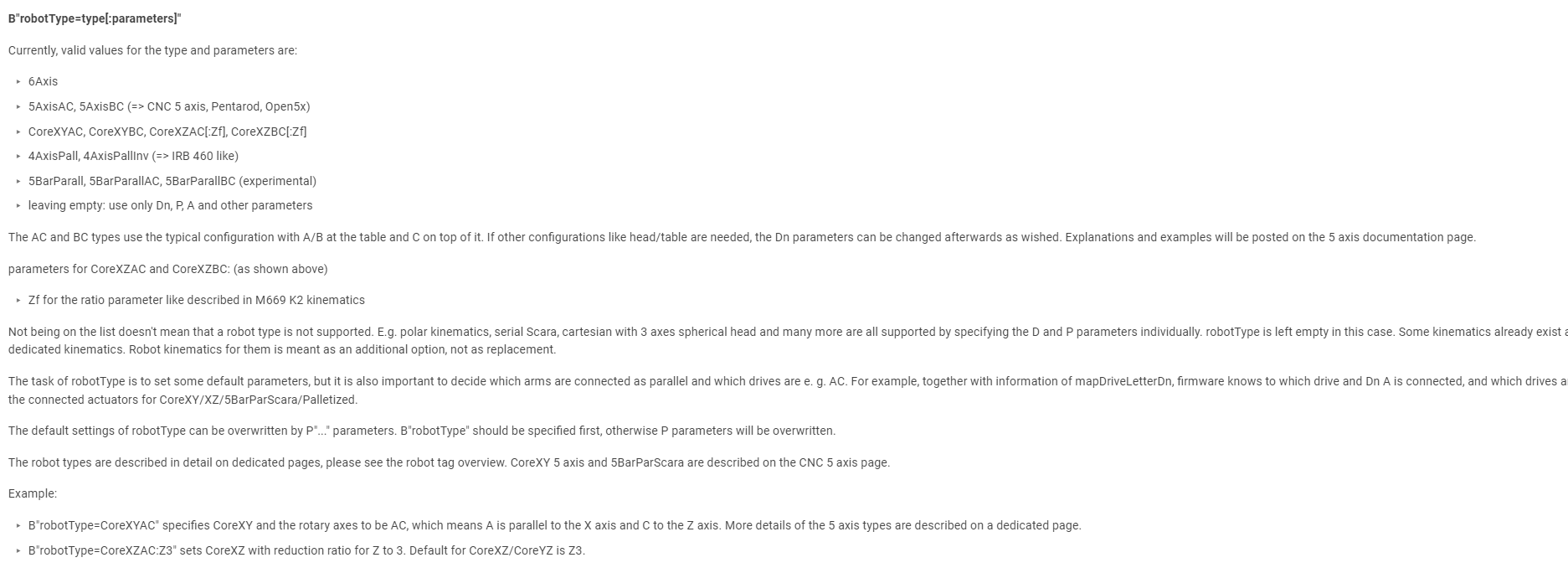
I read this https://docs.duet3d.com/User_manual/Machine_configuration/Configuring_RepRapFirmware_for_a_Robot_printer
and at the Moment I´m doing to prepare the g code.I´m not sure about robot type. I think ´´ leaving empty´´ is the right solution here?! because there is no 5 axisAB?
In the next hours and days, I´ll built my arm - then going ahead with software.
-
"Where the Ann and Bnn were the absolute rotations required to keep the end of the arm where you needed it for the XY positions of the main printer. That is basically doing the kinematics for this part of the system outside of the firmware."
To be not confused. After post-processing in cura, my g code should have A and B information, but in Angles and not in coordinates?
Example style: G1 X3.213 Y4.4 Z10 A39° B23.89° ? -
@IndeX4D yes that was my idea (except you would not add the degree signs) you would setup A and B as rotary axis and set the "steps/mm" to be "steps/degree".
-
@T3P3Tony
Ok that sounds like a good plan.
May there is somewhere a script which does exactly this? Otherwise I have to work on that..... could share it later.Drive assigment : M584 X0 Y1 Z2
M584 A3
M584 B4Is this ok when having 2 y-axis-motors`?
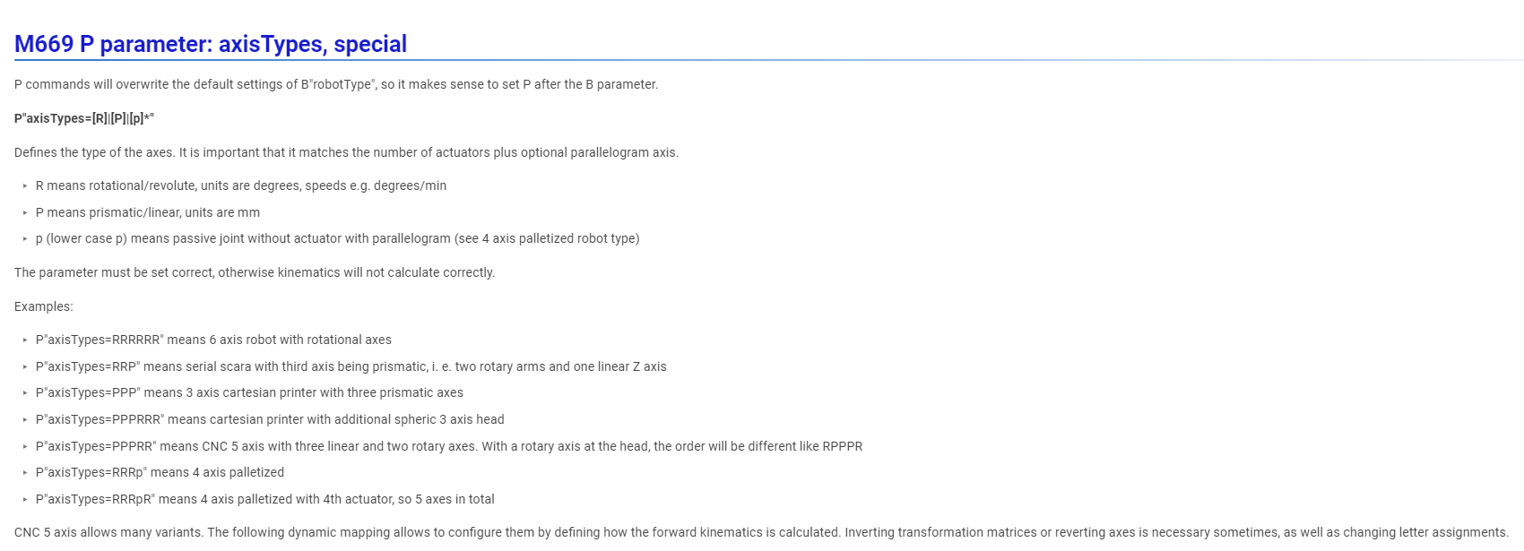
Axis type:
I guess I have to chooese --> P"axisTypes=PPPRR"
-