Skew calibration with calibration square? Maths help needed
-
I am aware that Duet3D have their own skew calibration method since the Ormerod times, but I recently used https://www.thingiverse.com/thing:2563185 on another machine and I think these somewhat easier to print and measure squares could also be used to compute the angles RRF requires for skew compensation.
But I lack the maths brain to do so. Has anyone done this or can help me out how to get from measuring the diagonals and width to the RRF values?
<>RatRig V-Minion Fly Super5Pro RRF<> V-Core 3.1 IDEX k*****r <> RatRig V-Minion SKR 2 Marlin<>
-
it is complicated , as your measuring across the corner . who wrote the code for the compensation?
<
-
@oliof You need to work out the amount of deviation from perpendicular for each axis, for XY, YZ and XZ. RRF uses M556, and there's a guide here: https://docs.duet3d.com/en/User_manual/Tuning/Orthogonal_axis_compensation
Marlin seems to be able to take the diagonal measurements and calculate these itself, then uses it in M852. Details and formulae here https://github.com/MarlinFirmware/Marlin/blob/7503ac3c67b1521f8d2c822f51b46c97a884a21e/Marlin/Configuration.h#L2162
You could use a macro and meta Gcode to input the diagonals, then calculate and set the M556 for you (just checking with @dc42 if RRF can actually accept user input in a macro...)
Ian
Bed-slinger - Mini5+ WiFi/1LC | RRP Fisher v1 - D2 WiFi | Polargraph - D2 WiFi | TronXY X5S - 6HC/Roto | CNC router - 6HC | Tractus3D T1250 - D2 Eth
-
@droftarts Klipper uses the diagonals to compute as well, see https://www.klipper3d.org/Skew_Correction.html
A Macro with parameters would be nice, I just need to know the maths (-:
-
@oliof It's in the Marlin firmware link I posted:
 * Marlin automatically computes skew factors from these measurements.
 * Skew factors may also be computed and set manually:
 *
 *  - Compute AB     : SQRT(2*AC*AC+2*BD*BD-4*AD*AD)/2
 *  - XY_SKEW_FACTOR : TAN(PI/2-ACOS((AC*AC-AB*AB-AD*AD)/(2*AB*AD)))
 *
 * If desired, follow the same procedure for XZ and YZ.
 * Use these diagrams for reference:
 *
 *    Y                     Z                     Z
 *    ^     B-------C       ^     B-------C       ^     B-------C
 *    |    /       /        |    /       /        |    /       /
 *    |   /       /         |   /       /         |   /       /
 *    |  A-------D          |  A-------D          |  A-------D
 *    +-------------->X     +-------------->X     +-------------->Y
 *     XY_SKEW_FACTOR        XZ_SKEW_FACTOR        YZ_SKEW_FACTOR
Ian
Bed-slinger - Mini5+ WiFi/1LC | RRP Fisher v1 - D2 WiFi | Polargraph - D2 WiFi | TronXY X5S - 6HC/Roto | CNC router - 6HC | Tractus3D T1250 - D2 Eth
-
@moth4017 you could probably check the source code repositories to figure out who wrote it.
-
@droftarts Thanks, I completely missed that (-: I think I will be able to sort it from here.
-
@oliof M291 in RRF v3.5beta1 has been extended to allow user input with S4/5/6/7. But you can just have a gcode with a list of variables to set, get it to "do the math(s)" and set M556.
Ian
Bed-slinger - Mini5+ WiFi/1LC | RRP Fisher v1 - D2 WiFi | Polargraph - D2 WiFi | TronXY X5S - 6HC/Roto | CNC router - 6HC | Tractus3D T1250 - D2 Eth
-
@droftarts a parametrized macro would be perfectly fine.
<>RatRig V-Minion Fly Super5Pro RRF<> V-Core 3.1 IDEX k*****r <> RatRig V-Minion SKR 2 Marlin<>
-
@oliof Okay, that took a little time! Marlin's M852 uses the ‘skew factor'; Klipper and Marlin (in configuration.h) allow you to put the measured diagonals in, and calculates the skew factor from them. RRF's M556 uses the physical distance of measuring points, and converts these internally, or put the skew factor in directly (see following post).
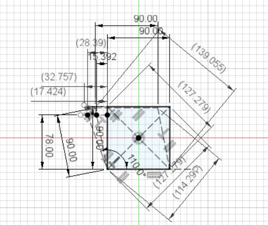
To allow RRF to use the diagonal measurement of a test piece, we need to calculate the skew factor from those measurements. I drew a quick test in OnShape to check my maths:
You can play around with this here (open 'Sketch1' and select 'Top' view): https://cad.onshape.com/documents/6ff12352632c0ad7ab55a879/
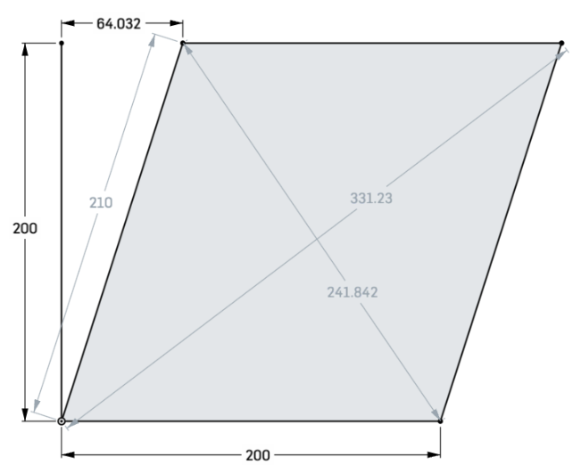
And then did some meta Gcode to calculate the skew distance/factor using the Marlin formulae. The file below calculates the distance AB for each of XY, XZ and YZ, then calculates the (Marlin) skew factor (which could be used directly to set M556, see following post), then calculates the skew mm offset for the given side length (AD - this is the same for XY, XZ and YZ, though could be changed so they can be different) for M556 in RRF. It sets M556, then sends M556 again to report the skew factor in use, which should look like the Marlin skew value, as RRF converts the skew mm offset to skew factor internally. Hope that helps!; Y Z Z ; ^ B-------C ^ B-------C ^ B-------C ; | / / | / / | / / ; | / / | / / | / / ; | A-------D | A-------D | A-------D ; +-------------->X +-------------->X +-------------->Y var AD = 200 var XY_AC = 331.229 var XY_BD = 241.842 var XY_skew_mm = 0 var XZ_AC = 262.488 var XZ_BD = 304.795 var XZ_skew_mm = 0 var YZ_AC = 283.551 var YZ_BD = 282.137 var YZ_skew_mm = 0 ; Compute XY var XY_AB = sqrt((2 * (var.XY_AC * var.XY_AC)) + (2 * (var.XY_BD * var.XY_BD)) - (4 * (var.AD * var.AD)))/2 var XY_skew_factor = tan(pi/2-acos((var.XY_AC * var.XY_AC - var.XY_AB * var.XY_AB - var.AD * var.AD)/(2 * var.XY_AB * var.AD))) if (var.XY_AC-var.XY_BD>=0) set var.XY_skew_mm = sqrt(var.XY_AB * var.XY_AB - var.AD * var.AD) else set var.XY_skew_mm = -sqrt(var.XY_AB * var.XY_AB - var.AD * var.AD) ; Compute XZ var XZ_AB = sqrt((2 * (var.XZ_AC * var.XZ_AC)) + (2 * (var.XZ_BD * var.XZ_BD)) - (4 * (var.AD * var.AD)))/2 var XZ_skew_factor = tan(pi/2-acos((var.XZ_AC * var.XZ_AC - var.XZ_AB * var.XZ_AB - var.AD * var.AD)/(2 * var.XZ_AB * var.AD))) if (var.XZ_AC-var.XZ_BD>=0) set var.XZ_skew_mm = sqrt(var.XZ_AB * var.XZ_AB - var.AD * var.AD) else set var.XZ_skew_mm = -sqrt(var.XZ_AB * var.XZ_AB - var.AD * var.AD) ; Compute YZ var YZ_AB = sqrt((2 * (var.YZ_AC * var.YZ_AC)) + (2 * (var.YZ_BD * var.YZ_BD)) - (4 * (var.AD * var.AD)))/2 var YZ_skew_factor = tan(pi/2-acos((var.YZ_AC * var.YZ_AC - var.YZ_AB * var.YZ_AB - var.AD * var.AD)/(2 * var.YZ_AB * var.AD))) if (var.YZ_AC-var.YZ_BD>=0) set var.YZ_skew_mm = sqrt(var.YZ_AB * var.YZ_AB - var.AD * var.AD) else set var.YZ_skew_mm = -sqrt(var.YZ_AB * var.YZ_AB - var.AD * var.AD) echo "XY: AB ", var.XY_AB, " Skew mm " , var.XY_skew_mm, " Skew factor ", var.XY_skew_factor echo "XZ: AB ", var.XZ_AB, " Skew mm " , var.XZ_skew_mm, " Skew factor ", var.XZ_skew_factor echo "YZ: AB ", var.YZ_AB, " Skew mm " , var.YZ_skew_mm, " Skew factor ", var.YZ_skew_factor M556 S{var.AD} X{var.XY_skew_mm} Y{var.XZ_skew_mm} Z{var.YZ_skew_mm} M556Sample output:
M98 P"0:/macros/Skew calibration"
XY: AB  210.0002  Skew mm  64.03204  Skew factor  0.3201567
XZ: AB  202.2374  Skew mm  -29.9996090  Skew factor  -0.1500003
YZ: AB  200.0031  Skew mm  1.105738  Skew factor  0.0049993
Axis compensations - XY: 0.32016, YZ: -0.15000, ZX: 0.00553
Ian
Bed-slinger - Mini5+ WiFi/1LC | RRP Fisher v1 - D2 WiFi | Polargraph - D2 WiFi | TronXY X5S - 6HC/Roto | CNC router - 6HC | Tractus3D T1250 - D2 Eth
-
@oliof Also just found out (from @dc42) that if you use S1 in M556 then XYZ values are the skew factors!
Ian
Bed-slinger - Mini5+ WiFi/1LC | RRP Fisher v1 - D2 WiFi | Polargraph - D2 WiFi | TronXY X5S - 6HC/Roto | CNC router - 6HC | Tractus3D T1250 - D2 Eth
-
@droftarts Fantastic, thanks!
-
@oliof No worries, good meta gcode practice for me! I'm updating the main post for clarity, so might change in the next few minutes (but not the code). Let me know if you need it to do something different.
Ian
Bed-slinger - Mini5+ WiFi/1LC | RRP Fisher v1 - D2 WiFi | Polargraph - D2 WiFi | TronXY X5S - 6HC/Roto | CNC router - 6HC | Tractus3D T1250 - D2 Eth
-
@droftarts I think just adding parameters so this can be put in as an M556.1 would be a great addition.
-
@oliof I asked @dc42 that exact question, with that exact Gcode! However, I'm not even sure how many people are using skew compensation as to whether it's worth it, now that there is this workaround for diagonal lengths. Probably not a high priority. Feel free to add it to the firmware wishlist, though, see if it gets any traction.
It's also a question about whether this is a more accurate method of measuring skew than the existing method, though at least it doesn't need any extra vitamins. The accuracy of both methods depends on whether there are corner bulges and how uniform/good the print is. Any feedback on that would be useful.
Ian
Bed-slinger - Mini5+ WiFi/1LC | RRP Fisher v1 - D2 WiFi | Polargraph - D2 WiFi | TronXY X5S - 6HC/Roto | CNC router - 6HC | Tractus3D T1250 - D2 Eth
-
@droftarts
I'm not sure I agree with your drawing (as it applies to the calculations in Marlin).
If the X and Y axis are skewed you should end up with a rhombus.
i.e. all four sides are the same lengths, but the corner angles are no 90 degrees.
I came up with this macro
It requires RRF 3.5.0b1+ as it takes user input in M291
When you enter the measured length of the first diagonal it calculates what the other diagonal should be and puts that in as the default.I have checked my calculations against this formula and they seem correct.
It also seems to work with the 100mm3 test piece I printed, although my printed Z dimensions do not match what they should be.
Someone has logged this as a bug, so I'm not sure if that's the causeI think if we use M556 P1, the results can be directly applied.
I'd love if someone could review my methodology.
EDIT:
Code changed to correct mistake in calculating area and expected diagonals of rhombus; set_skew_M556.g ; calculate the skew values based on diagonal measurements of a test object ; https://www.thingiverse.com/thing:2972743/comments ; Mark the test point corners A,B,C,D as per the diagram below ; computation formulae from Marlin firmware ; - Compute AB : SQRT(2*AC*AC+2*BD*BD-4*AD*AD)/2 ; - XY_SKEW_FACTOR : TAN(PI/2-ACOS((AC*AC-AB*AB-AD*AD)/(2*AB*AD))) ; If desired, follow the same procedure for XZ and YZ. ; ; Use these diagrams for reference: ; ; Y Z Z ; ^ B-------C ^ B-------C ^ B-------C ; | / / | / / | / / ; | / / | / / | / / ; | A-------D | A-------D | A-------D ; +-------------->X +-------------->X +-------------->Y ; XY_SKEW_FACTOR XZ_SKEW_FACTOR YZ_SKEW_FACTOR var xySkew = 0 var xzSkew =0 var yzSkew = 0 M291 S3 P"Measure X-Y Skew?" R"Measure X-Y" G4 P200 ; Maximum size limited to whichever axis is smallest var max = min(move.axes[0].max,move.axes[1].max,move.axes[2].max) M291 S6 P{"Enter side length of square (mm) max = " ^ var.max} R"Square" L10 H{var.max} F100.00 J1 var calculatedDiagonal = sqrt((input*input) + (input*input)) var A_D = input var x2 = move.axes[0].max * move.axes[0].max var y2 = move.axes[1].max * move.axes[1].max ; limit the diagonal to teh max possible iin the print volume var maxDiagonal = sqrt(var.y2 + var.x2) M291 S6 P"Enter A -> C measurement" R"A -> C" R"X -> Y" F{var.calculatedDiagonal} L10.0 H{var.maxDiagonal} J1 var A_C = input ; calculate area of rhombus given one side and diagonal ; 1/2 var.A_D sqrt(4*var.A_D*var.A_D) - var.A_C * var.A_C var area = 1/2* var.A_C * sqrt(4 * var.A_D * var.A_D - var.A_C * var.A_C) echo "Area = " ^ var.area var difXY = (var.area / var.A_C) * 2 ; calculates second diagonal of a rhombus given length of first M291 S6 P"Enter B -> D measurement" R"B -> D" R"X -> Y" F{var.difXY} L10.0 H{var.maxDiagonal} J1 var B_D = input var A_B = sqrt((2 * var.A_C * var.A_C) + (2 * var.B_D * var.B_D) - (4 * var.A_D * var.A_D))/2 set var.xySkew = tan(pi/2-acos((var.A_C*var.A_C-var.A_B*var.A_B-var.A_D*var.A_D)/(2*var.A_B*var.A_D))) echo "Set M556 for X-Y Skew to M556 S1 X" ^ var.xySkew ^ " Ynn Znn" G4 P200 M291 S4 P{"Apply skew (" ^ var.xySkew ^ ") to X-Y?"} R"Apply?" K{"Yes","No"} F0 J1 if input = 0 M556 S1 X{var.xySkew} else set var.xySkew = 0 ; revert back to zero as not applied G4 P200 ; move to X Z M291 S3 P"Continue to X-Z Skew?" R"Measure X-Z" G4 P200 M291 S6 P"Enter A -> C measurement" R"A -> C" R"X -> Z" F{var.calculatedDiagonal} L10.0 H{var.maxDiagonal} J1 set var.A_C = input set var.area = 1/2* var.A_C * sqrt(4 * var.A_D * var.A_D - var.A_C * var.A_C) var difXZ = (var.area / var.A_C) * 2 ; calculates second diagonal of a rhombus given length of first echo var.difXZ M291 S6 P"Enter B -> D measurement" R"B -> D" R"X -> Z" F{var.difXZ} L10.0 H{var.maxDiagonal} J1 set var.B_D = input set var.A_B = sqrt((2 * var.A_C * var.A_C) + (2 * var.B_D * var.B_D) - (4 * var.A_D * var.A_D))/2 set var.xzSkew = tan(pi/2-acos((var.A_C*var.A_C-var.A_B*var.A_B-var.A_D*var.A_D)/(2*var.A_B*var.A_D))) echo "Set M556 for X-Z skew to M556 S1 Xnn Ynn Z"^ var.xzSkew G4 P200 M291 S4 P{"Apply Skew (" ^var.xzSkew ^ ") to X-Z?"} R"Apply?" K{"Yes","No"} F0 J1 if input = 0 M556 S1 Z{var.xzSkew} else set var.xzSkew = 0 ; revert to zero as not applied G4 P200 ; move to Y Z M291 S3 P"Continue to Y-Z Skew?" R"Measure Y-Z" G4 P200 M291 S6 P"Enter A -> C measurement" R"A -> C" R"Y -> Z" F{var.calculatedDiagonal} L10.0 H{var.maxDiagonal} J1 set var.A_C = input set var.area = 1/2* var.A_C * sqrt(4 * var.A_D * var.A_D - var.A_C * var.A_C) var difYZ = var.area / var.A_C * 2 echo var.difYZ M291 S6 P"Enter B -> D measurement" R"B -> D" R"Y -> Z" F{var.difYZ} L10.0 H{var.maxDiagonal} J1 set var.B_D = input set var.A_B = sqrt((2 * var.A_C * var.A_C) + (2 * var.B_D * var.B_D) - (4 * var.A_D * var.A_D))/2 set var.yzSkew = tan(pi/2-acos((var.A_C*var.A_C-var.A_B*var.A_B-var.A_D*var.A_D)/(2*var.A_B*var.A_D))) echo "Set M556 for Y-Z skew to M556 S1 Xnn Y" ^ var.yzSkew ^ "Znn" M291 S4 P{"Apply skew (" ^var.yzSkew ^ ") to Y-Z?"} R"Apply?" K{"Yes","No"} F0 J1 if input = 0 M556 S1 Y{var.yzSkew} else set var.yzSkew = 0 ; revert back to zero as not applied if (move.compensation.skew.tanXY != var.xySkew) || (move.compensation.skew.tanXZ != var.xzSkew) || (move.compensation.skew.tanYZ != var.yzSkew) echo "Calculated skew settings should be:" echo "M556 S1 X" ^ {var.xySkew}^ " Y" ^ {var.yzSkew} ^ " Z" ^ {var.xzSkew} echo "Actual setting" M556 M291 S4 P{"One or more skew settings has not been applied - Apply Now?"} R"Settings not applied?" K{"Yes","No"} F0 J1 if input = 0 M556 S1 X{var.xySkew} Y{var.yzSkew} Z{var.xzSkew} M556 M291 S1 T10 P"Review results in console or send M556 to confirm" R"Done" -
@droftarts
I just ran your macro against mine and they essentially gave the same output when the same values were used, so I think I've misunderstood how you applied the measurements based on your drawing.var AD = 180 var XY_AC = 244 var XY_BD = 265.57 var XY_skew_mm = 0 var XZ_AC = 254.5584 var XZ_BD = 254.5584 var XZ_skew_mm = 0 var YZ_AC = 254.5584 var YZ_BD = 254.5584 var YZ_skew_mm = 0your output

My output

-
Thinking on all this, I have to say that in many ways, the RRF method of using the measured skew at a given distance from a plane does probably make for an easier method.
It means you don't have to worry about over/under extrusion or other factors affecting the printed part size.
If I'm using diagonals then it only works if the printed part is exactly dimensionally accurate. Especially if it's based on a cube or square.
If I print something that's supposed to be 100x100x100 and it ends up 99.6 x 100 x 101.2 then my macro doesn't really work.
But if I print something approximately 110x110x110 and measure the skew at 100mm from the plane then the angles will be correct regardless of the actual dimension.
To me that probably gives you more chance of getting accurate skew settings without other possible inaccuracies in the system getting in the way.
Alternately we'd have to measure the actual dimensions on each face and calculate to diagonals of a parallelogram.
In truth it's probably taken longer to do the macro to use diagonals than it would have to make a measuring tool per the RRF docs.As mentioned above, for some reason the diagonal measurement test piece I did was quite a bit out on the Z direction. (>1.5mm too high)
X & Y are near perfect (<0.2mm from dimension)
I have checked that Z steps are correct by measuring from frame to X gantry, carrying out a 100mm move and measuring again. Actual movement it exactly 100mm.
WTF?
Now I'm printing a plain 100mm cube to double check.
Down the rabbit hole I go
-
@OwenD Thanks for chiming in! I was thinking about this earlier, and I think you are correct. I took the Marlin formulae as correct, and didn't think it through. The shape produced from misaligned axes would be a rhombus not a parallelogram. The two axes, assuming they have been configured correctly, should move the set distance in their plane, so the square would deform into a rhombus.
So, we shouldn't be calculating AB; AB = AD. Your calculations work in the same way as mine, taken from Marlin; AB is calculated where the point B is perpendicular to AD, at the distance AD. I haven't sat down and drawn out the two formula that Marlin uses, I took it that they were correct... but perhaps they are not! I did notice some small differences when calculating the skew factor from the Marlin formulae vs from the measured skew (the old way of doing it).
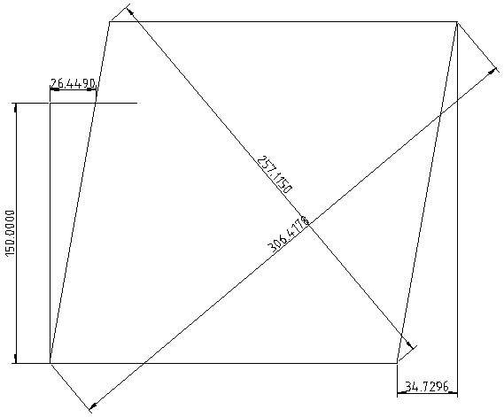
The interesting thing about the old way of doing this is that it is unambiguous. Take this:
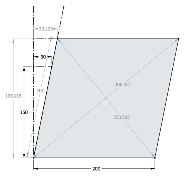
If you measure up 150mm, you get a skew distance of 30mm. Skew factor is 30/150=0.2
If I run these diagonals and AD of 200 through yours I get 0.1999988, and through mine I also get 0.1999988, which is, arguably, very close. But it feels it should work out to 0.2!However, as we're assuming the square deforms into a rhombus, the nice thing is that it makes an isosceles triangle with the diagonal measurements. So the trigonometry should be easy to do. But tomorrow, because it's a bit late here.
Ian
Bed-slinger - Mini5+ WiFi/1LC | RRP Fisher v1 - D2 WiFi | Polargraph - D2 WiFi | TronXY X5S - 6HC/Roto | CNC router - 6HC | Tractus3D T1250 - D2 Eth
-
@droftarts
I just realised I made a mistake in my calculations.
It only affected the calculation of the expected length of the diagonals and the area.
I was using the area of the square and not the rhombus.
If I use these dimensions with the RRF method and with my macro the results are essentially the same..
RRF Method

My macro