Tramming bed multiple times
-
I was wondering if the conditional gcode listed in the documentation which the example is for a delta printer can be used for leveling/tramming a corexy bed multiple times until it is within a certain deviation? It is just a nuisance having to run the bed.g manually multiple times especially using a Euclid probe that has to re-dock every time.
I don't really understand conditional gcode and programming so I have no idea if what I typed up/copied below would work.
If I was the mimic the example but put in my bed.g would this work?
M561 ; clear any bed transform
G28
M401 P0 ; pick up Euclid
G1 X290 Y32.5 Z5 F10000 ; go to first probe point to get ready
while true
if iterations = 5
abort "Too many calibration attempts"
G30 P0 X290 Y32.5 Z-99999 ; PROBE NEAR FRONT RIGHT
if result != 0
continue
G30 P1 X290 Y287.5 Z-99999 ; PROBE NEAR REAR RIGHT
if result != 0
continue
G30 P2 X40 Y159.5 Z-99999 S3 ; PROBE NEAR LEFT
if result !=0
continue
if move.calibration.initial.deviation <= 0.05
break
echo "Repeating calibration because deviation is too high (" ^ move.calibration.initial.deviation ^ "mm)"
;end loop
echo "Auto calibration successful, deviation", move.calibration.final.deviation ^ "mm"G1 X138 Y179 F9000 ; go to center of bed in advance of probe that point
G30 ; probe center of bed to re-establish Z
M402 P0 ;Return Euclid -
make sure when you copy it to your macro that all the spacing on each line is important else it wont work correctly.
while true if iterations = 5 abort "Too many auto calibration attempts" G30 P0 X17 Y17 Z-99999 ; probe starboard bow if result != 0 continue G30 P1 X293 Y17 Z-99999 ; probe port bow if result != 0 continue G30 P2 X293 Y283 Z-99999 ; probe port stern if result != 0 continue G30 P3 X17 Y283 Z-99999 S3 ; probe starboard stern S3 = 3 z axis if result != 0 continue if move.calibration.initial.deviation <= 0.04 break echo "Repeating calibration because deviation is too high (" ^ move.calibration.initial.deviation ^ "mm)" ; end loop echo "Auto calibration successful, deviation", move.calibration.final.deviation ^ "mm" -
@moth4017
For some reason it didn't post the spacing I had done. Is there a certain amount of spaces required or just that each section has the same offsets?I had done two spaces for each indent...
Another question, since I plan to put this all in my bed.g, the macro just has to call G32, correct?
-
@JamesM
2 spaces are fine , G32 calls the bed.g macro.
what problem do you have?this is my bed.g file, i dont have the same probe as you , but i am picking up a probe and dropping it off.
;G32  Auto calibration routine for large bed
M561                    ; clear any bed transform

; If the printer hasn't been homed, home it
if !move.axes[0].homed || !move.axes[1].homed || !move.axes[2].homed
  G28
M98 P"/macros/ProbePickUp"	; probe pick up

; Probe the bed and do auto calibration
G1 X14 Y44 Z30 F6000        ; go to just above the first probe point
while true
  if iterations = 5
    abort "Too many auto calibration attempts"
  G30 P0 X17 Y17 Z-99999               ; probe starboard bow
  if result != 0
    continue
  G30 P1 X293 Y17 Z-99999              ; probe port bow
  if result != 0
    continue
  G30 P2 X293 Y283 Z-99999             ; probe port stern
  if result != 0
    continue
  G30 P3 X17 Y283  Z-99999 S3          ; probe starboard stern   S3 = 3 z axis
  if result != 0
    continue
  if move.calibration.initial.deviation <= 0.04
    break
  echo "Repeating calibration because deviation is too high (" ^ move.calibration.initial.deviation ^ "mm)"
; end loop
echo "Auto calibration successful, deviation", move.calibration.final.deviation ^ "mm"
G1 F6000 X155 Y185					; probe to center bed
G30 F2000							;Single Z-Probe
M98 P"/macros/ProbeDropOff"	; probe drop off
G1 Z30 F10000                ; get the head out of the way
<
-
It's not a problem, just trying to save time from having to manually run my "equalize leadscrews" macro multiple times until everything is within what I believe is an acceptable deviation between my 3 leadscrews.
-
I just tried it and it only ran it once but I know for sure if I run it again the deviation is not going to be 0.000 like the results say.
I guess I need to need to try and learn how to program this so it automatically runs the probing at least 3 times but I'm totally clueless with this stuff unfortunately...lol.
-
it would be unusual to get a deviation of 0.000 , perhaps try a probe test .
something like this and see what the results are like.
M291 P"Probe will be tested 10 times and return mean and standard deviation. Ok or Cancel?" R"WARNING" S3 ; User must click OK or cancel. G30 P0 X155 Y155 Z-9999 G30 P1 X155 Y155 Z-9999 G30 P2 X155 Y155 Z-9999 G30 P3 X155 Y155 Z-9999 G30 P4 X155 Y155 Z-9999 G30 P5 X155 Y155 Z-9999 G30 P6 X155 Y155 Z-9999 G30 P7 X155 Y155 Z-9999 G30 P8 X155 Y155 Z-9999 G30 P9 X155 Y155 Z-9999 S-1 -
@JamesM Just to say that you might want to consider adding another check. Also, that you are probably probing at the wrong positions (most people do). I did a YouTube video about this but I'm on my phone right now so not easy to post a link. If you look at my sig, you'll see a link to my yt channel where you can find the video l made about bed levelling.
But in a nutshell, if you probe near each of the 3 lead screws, you'll end up with a flat plane but it won't necessarily be tram if you have any sort of twist in the frame. That is to say, you'll have a flat plane that is tram with a plane described by the lower lead screw positions but necessarily tram with the upper frame members on which the XY gantry runs. Assuming you have lead screws at front left, front right, and rear centre, after levelling the bed, you should then check rear right, rear left and front centre. If the bed to nozzle distance at any of these points is off, then you have a twist in the upper frame members which needs to be corrected.EDIT - now that I'm in front of a computer, here is a link to the video I mentioned https://www.youtube.com/watch?v=H9O1r46Izn8
-
@JamesM said in Tramming bed multiple times:
I just tried it and it only ran it once but I know for sure if I run it again the deviation is not going to be 0.000 like the results say.
The reported new deviation is only meaningful if you use more probe points than you have Z motors. If you have the same number then it will always be reported as zero.
-
@deckingman
My leadscrews are actually one in the middle left and two on the right side. I have the railcore II cast bed from 713maker on my BLV cube printers.I was always under the impression that I was supposed to do my bed.g with probing by the leadscrews but if that's not the case then I'll change that. I assumed that is how it was supposed to be set up since the Duet documentation lists this example:
G28 ; home
G30 P0 X20 Y190 Z-99999 ; probe point 0 near a leadscrew
G30 P1 X180 Y190 Z-99999 ; probe point 1 near a leadscrew
G30 P2 X100 Y10 Z-99999 S3 ; probe point 2 near a leadscrew and calibrate 3 motors
Should I still probe by the leadscrews and then add additional locations such the left rear, left front and also the right center and then rear center and front center?
Something like this
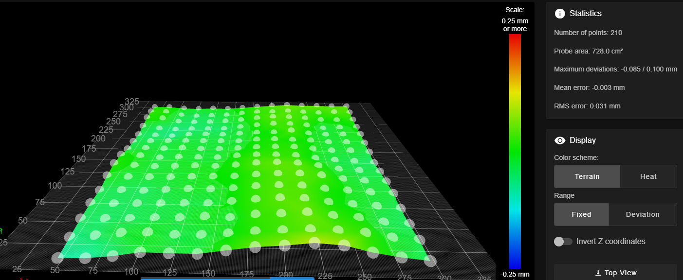
M562 ;clear bed transform G28 ;home all M401 P0 ;pickup Euclid probe G30 P0 X310 Y32.5 Z-99999 ; right front leadscrew G30 P1 X310 Y179 Z-99999 ;right center G30 P2 X310 Y287.5 Z-99999 ; right rear leadscrew G30 P3 X40 Y290 Z-99999 ;left rear G30 P4 X40 Y159.5 Z-99999 ;left center leadscrew G30 P5 X40 Y30 Z-99999 ;left front G30 P6 X138 Y30 Z-9999 ;front middle G30 P7 X138 Y290 Z-99999 S3 ;rear center G1 X138 Y179 F9000 ;go to center of bed in advance of probe that point G30 ;probe center to re-establish Z M402 P0 ;Return Euclid probe -
Gave me a pretty nice heightmap
-
@JamesM Did you watch my YT video? If not, I suggest you do. To summarise (again), if you probe close to the lead screws, you'll get a plain that is level to a plain described by the bottom fixing positions of the lead screws. However, with a cuboid shaped printer frame, the XY gantry will run on rails fixed to the top of the frame. If the XY rails aren't absolutely parallel with the lower fixing positions of the lead screws, then they won't be tram with your (levelled) bed. So regardless of the actual positions of the lead screws, after levelling the bed, it's a good idea to check the diametrically opposite positions.
If you are absolutely sure that your frame is perfectly square (within say 0.1mm) and that the frame will stay that way, then you can omit that check.
I made my comments based on your title which refers to "tramming" as opposed to "levelling". A build plate might be level, but if it isn't level with respect to the XY axes of the print head, then it won't be tram. -
@deckingman hi great video, so it got me thinking if you have a good probe ( good repeatability ) you could apply the same measures technique as you used with the dial gauge to do an auto tram to see if the frame is twisted if your using mutiple motors , side note my core xy i build 6 years a go has three lead screws and 1 motor and a belt and i used the same technique to alter the height ..
-
@JamesM This new bed.g would trigger the bed tramming, since it has more probe points than leadscrews.
But it doesn't repeat the probing if deviation is bigger than 0.x.
You'd have to wrap the code between pickup euclid probe and return euclid probe in a while loop, as shown before. -
@deckingman
Yes, I did watch your video and I think I had actually watched it in the past.I do seem to be getting better prints with the additional probing now but I do think I'll need to tweak my bed mesh manually since there are still a few spots when printing where I'll get the filament ripple on the first few layers from when it is too close.
-
@JamesM I don't use any form of flatness or levelling compensation, so I can't comment on your mesh results. But I have found in the past that a slight change to the overall Z offset will fix first layer rippling if it occurs, even if that ripple is only across part of the print. On my machine at least, it seems that if one bead of filament lifts slightly due to a spec of dust or for some other reason, then subsequent touching beads will also lift at the same spot. Generally reducing the offset by 0.05 or 0.1mm is enough to cure the problem for me.
Edit. To be clear, if I find that the bed is level but not tram with print head, I fix the problem with the frame, rather than using mesh compensation. -
@deckingman said in Tramming bed multiple times:
I fix the problem with the frame, rather than using mesh compensation.
Many people underestimate gantry sag. They spend $$$ for an extra flat bed, but it still doesn't work. (don't ask, how I know
") )
) -
@o_lampe said in Tramming bed multiple times:
......... Many people underestimate gantry sag. They spend $$$ for an extra flat bed, but it still doesn't work. (don't ask, how I know
)That too can be a problem. Personally I use two parallel rails with my (heavy) hot end fixed between them. No sagging but it does take a up a bit of potential travel in the Y direction compared to a single rail.
-
@deckingman & @o_lampe
On my big ratrig v-core 3.1 I suspect it has some gantry sag..it's a big printer...500x500. I am re-doing a few things on that right now, replaced the gantry extrusion with a quality one from misumi, re-printed most of the printed parts, new y-linear rails since one that came with it was less than ideal.I'm really curious to see how it is after all the replacements I'm doing on it. I even had two small custom extrusions cut from misumi to use as alignment spacers for the extrusions the y-rails mount to so they would be precisely lined up.