Rough print finish and dimensional inaccuracy
-
Hello, I have modified my Ender 5 Plus with a Duet 3 with an E3D Hemera and Volcano. I am getting a rough finish which looks unappealing and causes dimensional inaccuracy. I have leveled the bed, tensioned the belts, calibrated E-Steps, calibrated XYZ steps using calibration cube, and calibrated flow. With a maximum deviation of +-0.03mm, which is tolerable. However, I am still having poor print quality. I am attaching photos and have highlighted problem areas. My config.g:
-
; Configuration file for Duet 3 MB 6HC (firmware version 3.3)
; executed by the firmware on start-up
;
; generated by RepRapFirmware Configuration Tool v3.3.12 on Mon Sep 05 2022 02:51:18 GMT-0700 (Pacific Daylight Time)
G4 S5
; General preferences
G90                                              ; send absolute coordinates...
M83                                              ; ...but relative extruder moves
M550 P"Duet 3"                                   ; set printer name
; Drives
M569 P0.0 S1                                     ; physical drive 0.0 goes forwards
M569 P0.1 S1                                     ; physical drive 0.1 goes forwards
M569 P0.2 S1                                     ; physical drive 0.2 goes forwards
M569 P121.0 S0                                   ; physical drive 121.0 goes forwards
M584 X0.0 Y0.1 Z0.2:0.3 E121.0                       ; set drive mapping
M350 X16 Y16 Z16 E16 I1                          ; configure microstepping with interpolation
M92 X79.9 Y79.8 Z798.929 E409                ; set steps per mm
M566 X900.00 Y900.00 Z60.00 E3000              ; set maximum instantaneous speed changes (mm/min)
M203 X6000.00 Y6000.00 Z180.00 E7200          ; set maximum speeds (mm/min)
M201 X500.00 Y500.00 Z20.00 E6000              ; set accelerations (mm/s^2)
M906 X800 Y800 Z800 E1100 I30                    ; set motor currents (mA) and motor idle factor in per cent
M84 S30                                          ; Set idle timeout              ; Set idle timeout
M671 X290:290:40:40 Y0:270:0:270 P0.5

; Axis Limits
M208 X0 Y0 Z0 S1                                ; set axis minima
M208 X295 Y320 Z250 S0                           ; set axis maxima

; Endstops
M574 X2 S1 P"io0.in"                             ; configure switch-type (e.g. microswitch) endstop for high end on X via pin io0.in
M574 Y2 S1 P"io1.in"                             ; configure switch-type (e.g. microswitch) endstop for high end on Y via pin io1.in
M574 Z1 S2                                       ; configure Z-probe endstop for low end on Z

; Z-Probe
M950 S0 C"121.io0.out"                           ; create servo pin 0 for BLTouch
M558 P9 C"121.io0.in" H5 F600 T12000 A2 S0.03 R0.4  ; set Z probe type to bltouch and the dive height + speeds
G31 P500 X-50 Y-15 Z3.9
M557 X15:295 Y5:315 S35                         ; define mesh grid
M591 D0 P3 C"121.io1.in" R80:140  E7.5 L24.54 S1  ; filament monitor

; Heaters
M308 S0 P"temp0" Y"thermistor" T100000 B3950     ; configure sensor 0 as thermistor on pin temp0
M950 H0 C"out0" T0                               ; create bed heater output on out0 and map it to sensor 0
M307 H0 B0 S1.00                                 ; disable bang-bang mode for the bed heater and set PWM limit
M140 H0                                          ; map heated bed to heater 0
M143 H0 S100                                     ; set temperature limit for heater 0 to 120C
M308 S1 P"121.temp0" Y"pt1000"                   ; configure sensor 1 as PT1000 on pin 121.temp0
M950 H1 C"121.out0" T1                           ; create nozzle heater output on 121.out0 and map it to sensor 1
M307 H1 B0 S1.00                                 ; disable bang-bang mode for heater  and set PWM limit
M143 H1 S500                                     ; set temperature limit for heater 1 to 450C
; Fans
M950 F0 C"121.out1" Q500 ; create fan 0 on pin 121.out1 and set its frequency
M106 P0 C"Print Cooling fan" S0 H-1       ; set fan 0 value. Thermostatic control is turned off

M950 F1 C"121.out2" Q500                         ; create fan 1 on pin 121.out2 and set its frequency
M106 P1 C"Hotend Fan" S1 H1 T45                                ; set fan 1 value. Thermostatic control is turned on
; Tools
M563 P0 S"E3D Hemera with Volcano" D0 H1 F0                   ; define tool 0
G10 P0 X0 Y0 Z0                                  ; set tool 0 axis offsets
G10 P0 R0 S0                                     ; set initial tool 0 active and standby temperatures to 0C
M912 P0 S-10
G4 S5
M591 D0
M570 H1 P15 T30 ; An anomaly on heater 1 must persist for 4 seconds, and must be greater or less than 15C from the setpoint, to raise a heater fault.
M501


Cura Profile:
How do I get a smooth finish and make it dimensionally accurate?
-
@TRATOON I also just noticed the dimensional inaccuracies are along the x axis, everything the y axis does is fine.
-
@TRATOON is it that the X axis exhibits a small random shift, i.e. if a layer slightly overhangs the previous layer at one side then it is slightly indented at the other side?
Duet WiFi hardware designer and firmware engineer
Please do not ask me for Duet support via PM or email, use the forum
http://www.escher3d.com, https://miscsolutions.wordpress.com -
@dc42 No the layers are just coming out at both sides of X axis it is not where one side overhangs and then that same layer is indented on other side. For example, at the bottom left side, it is pretty much perfectly smooth, but on the right side, only some of those layers are protruding. For some reason, one side of the X axis is always smooth while the other is only slightly rough. And also, at the corners, a part sticks out, "corner ridges".
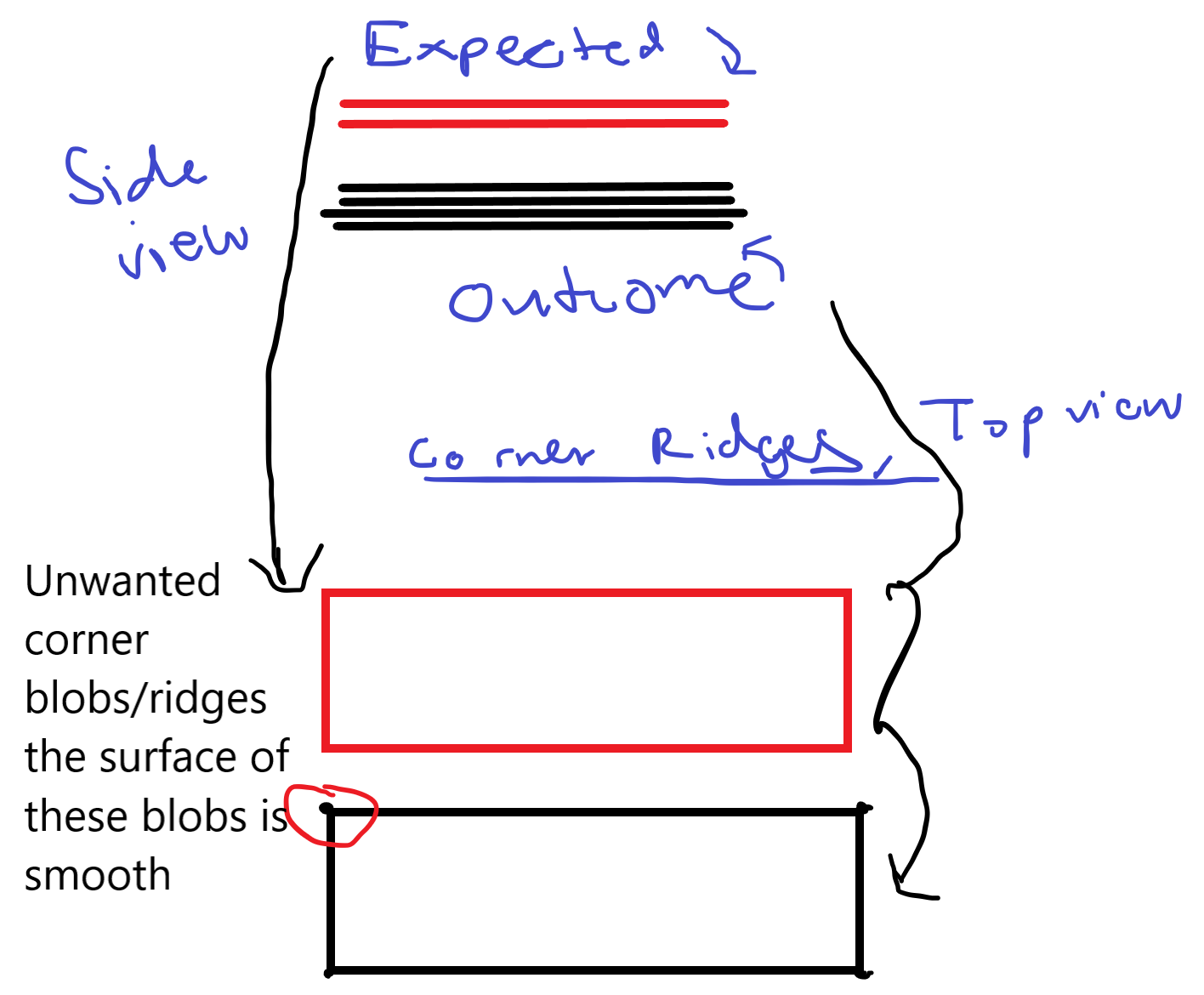 The first part shows the roughness, and the bottom shows these corner ridges that add to dimensional inaccuracy.
 -
Do you have another slicer setup to test against? Like Prusa Slicer?
-
@Phaedrux No, and I don't really want to because there are a lot of settings that would need to be changed and I'm not sure if it would behave the same.
-
@TRATOON if you rotate the object your printing 90 degrees on the bed does the bad printed side follow the rotation? Or remain on the same axis ? If so could you have a mechanical problem.
-
@moth4017 The whole part has a rough finish it is just worse along the X axis and this problem seems to get worse the bigger the part is. A 20mm calibration cube has an almost perfect finish but anything bigger than that has a rougher finish. But yes, the worst side is always along the X axis.
-
@TRATOON i guess you will need go back to first steps,
steps/mm for steppers
extruder steps/calibration ,etc etc
-
@TRATOON The squished out layer in your illustration looks like a Z axis problem- that layer is thinner than the others, but they use the same amount of plastic, so it has to go somewhere. Are you using a full step multiple for print layer thickness?
Another thing that can contribute to rough surface is the extruder filament drive gears, especially if it uses "dual drive".
Corner issues can be due to things like speed, acceleration, and pressure advance.
-
@mrehorstdmd My layer height is 0.2 mm and 0.3 mm for first layer.
-
@TRATOON How did you decide to use these steps/mm:
M92 X79.9 Y79.8 Z798.929 E409In general it is probably not a good idea to "calibrate" your printer by adjusting these values (especially if you are using a printed object as the calibration tool). It is possible that by using these values rather than 80, 80 800 (which is what I suspect the mechanics of your printer is set up to be), you may be making things worse as it is likely that you are now squeezing more plastic into a line/layer than the slicer expects. If when using the "standard" values for your printer your prints are not coming out at the correct size then I think you should be investigating why, rather than adjusting around the problem. See the following for more details... https://teachingtechyt.github.io/calibration.html#xyzsteps
-
@TRATOON said in Rough print finish and dimensional inaccuracy:
M92 X79.9 Y79.8 Z798.929 E409 ; set steps per mm
How did you arrive at 798.929 steps/mm in Z?
With screws/belts having even pitch values like 2 mm/rev, and motors usually having 200 steps/rev, you should not have such a weird value for Z steps/mm. I assume the numerical value you're looking for here is 800 steps/mm. A 200 um layer would then be 160 full steps. A 300 um layer would be 240 full steps.
You want to use full step multiples for layer thickness because you can't rely on microstepping to provide an accurate position. With your odd value of Z steps/mm, there's no telling what actual layer thickness you're going to end up with.
@gloomyandy is right about X and Y as well. With X being 79.9 steps/mm and Y being 79.8, a line in X will be a little longer than a line in Y. If the same amount of plastic is being deposited, the line will be thinner in X.
Video about Z axis problems due to dual drive gear extruder.
-
@gloomyandy Yes the values are supposed to be 80,80,800. However, I thought it was common practice to calibrate these values which is how I reached these values.
-
@mrehorstdmd What is step multiples for layer thickness? What layer height should I be using for 80,80,800?
-
@mrehorstdmd I am was using 10000mm/s/s for acceleration in cura and 80mm/s for speed but I reduced it to 2750 for acceleration and 60mm/s for speed and I saw a little improvement. iam nost sure what pressure advance is.
-
@TRATOON Is the 800 steps/mm full steps or is it based on 16:1 ustepping? or some other ustepping ratio?
A Z axis with 800 full steps/mm moves1.25 um per full step of the Z axis motor(s). Your print layer thickness should be any whole number multiple of 1.25 um. A 200 um layer will be 160 full steps. A 300 um layer will be 240 full steps. A 100 um layer 80 steps, etc.
If 800 steps/mm is based on 16:1 ustepping, then you actually have 50 full steps/mm or 20 um. In that case you can still print in 200 or 300 um layers, but don't print in 150 um layers because 150/20 = 7.5 : not a whole number.
Pressure advance is one of the various ways of tuning the extrusion to fix certain types of problems, especially blobbing in corners. See: https://docs.duet3d.com/en/User_manual/Tuning/Pressure_advance
-
@mrehorstdmd No it is just 800m/s no upstepping. So you are saying I set it back to 800m/s and I will be fine printing at 0.2 mm and 0.35mm as both of those are divisible evenly by 1.25um?
-
@TRATOON Your existing configuration is using 16 microsteps on Z see:
M350 X16 Y16 Z16 E16 I1so the 800 (or 798.929 as you currently have it) steps/mm will include that, which as above means 50 full steps/mm.
-
@TRATOON I'd say this was classic Z-banding, where the Z axis isn't moving the correct amount, due to not using a multiple of whole steps each layer. As @mrehorstdmd has pointed out, your Z steps per mm are Z798.929. Change it to Z800, and use a multiple of 0.02mm for your layer height. I'd be amazed if you can actually measure the 0.125% difference in height!
Personally I'd use whole numbers for steps per mm, and if you need to scale the print afterwards, use M579 to scale axes (but not Z). Though I think once it is printing nicely in Z, you'll find the X, Y and Z dimensions are more accurate. If Z scaling is noticeable, you will be better off scaling in the slicer, so you maintain the Z layer height.
Also, your Z axis is using two drivers (
M584 X0.0 Y0.1 Z0.2:0.3 E121.0), but you don't have an M569 for the second driver. Add this to config.g (check S parameter makes the motor go the correct direction):M569 P0.3 S1 ; physical drive 0.3 goes forwardsIan