challenge: controlling 88 output pins
-
Hello,
I would like to use the Duet3D 6HC main board for running a 3 axis 3d-printer. This printer however, uses 88 valves+nozzles to spray water on a print bed. It does this in a scanning motion, so for every X position there is a certain state (open/close) of all the 88 valves. This means I need 88 digital outputs.. which is not trivial on the Duet3d.
I was wondering what kind of ideas some of the experts here have to make this possible. I have full freedom in the design of the electronics that actually control the valves, so I could add a CAN or UART based port expanders, or some Ethernet based solution etc. Important is that the 88 outputs are controllable from the g-code (currently, in my prototype, I am using 3 valves using the M670 IO port bit mapping feature, but this won't scale up to 88 outputs as far as I know).
I am also considering a alternative solution of just sending the X position (either as a absolute value, or as a pulse-signal) to a external controller which has the pattern of the valves stored, which then sends the signals to the valves based on the position. But this is a bit more complex logistically, as each time the pattern needs to be uploaded to the external controller, plus the two need to communicate to synchronize beforehand). I prefer having everything in one g-code file.
I am curious what you think could be the possibilities, and what would be the easiest to implement / utilize.
-
@arvest I think it would make more sense to encode the X position and pass that to a controller that operates the 88 valves. How many bits of resolution would you need in the X position? M670 is currently limited to 16 bits.
Duet WiFi hardware designer and firmware engineer
Please do not ask me for Duet support via PM or email, use the forum
http://www.escher3d.com, https://miscsolutions.wordpress.com -
@dc42 For a accuracy of 0.2 mm over 1000 mm, I guess around 13 bits would be the minimum. However, as the X motion is a constant speed motion, I can also imagine sending pulses every 0.2mm, possibly with some sync pulses every X centimeters.
-
@arvest I would do something like use the second UART to connect to an Arduino or other small microcontroller and send messages using M115 containing the next pattern for the 88 outputs.
This could be 88 1/0 characters or something smarter using 4 or more bits-per character.
The Arduino could be connected to an 11-stage shift register using one of the many serial-to-parallel shift registers available like the 74595
After shifting out the pattern, the Arduino-like thing would wait for an individual GPIO from the Duet to latch all 88 outputs and turn on the nozzles.
You could also use M115 to send messages setting the duration of the output pulses and have the Arduino-thing turn them all off after some time.
Using shift registers with a separate storage register and output stage allows you to completely synchronize all 88 outputs so they turn on at the same time and not one-at-a-time.
SeemeCNC Rostock Max V3 converted to V3.2 with a Duet2 Ethernet Firmware 3.2 and SE300
-
@arvest said in challenge: controlling 88 output pins:
@dc42 For a accuracy of 0.2 mm over 1000 mm, I guess around 13 bits would be the minimum. However, as the X motion is a constant speed motion, I can also imagine sending pulses every 0.2mm, possibly with some sync pulses every X centimeters.
88 nozzle over 1000mm gives a spacing of 11.3mm between nozzles if they are in a single row, more if they are in multiple rows. So do you really need a resolution of 0.2mm? I would have thought 5mm would be more than adequate.
Is the nozzle energising pattern very simple, e.g. energise the 6 nozzles closest to the current X coordinate?
Duet WiFi hardware designer and firmware engineer
Please do not ask me for Duet support via PM or email, use the forum
http://www.escher3d.com, https://miscsolutions.wordpress.com -
@arvest I think a sketch of the critical parts of the design would be helpful.
The Y axis has 88 nozzles, spaced out, scanning over the X axis? X axis travel is 1000mm? The on/off settings of the valves need to be updated every 0.2mm of Taxis travel? At what maximum speed?
-
@arvest wouldnt spi driven i/o expanders be the easiest option? I not that familiar w spi on duet/rrf, but I think end user has full control of protocol and data...
-
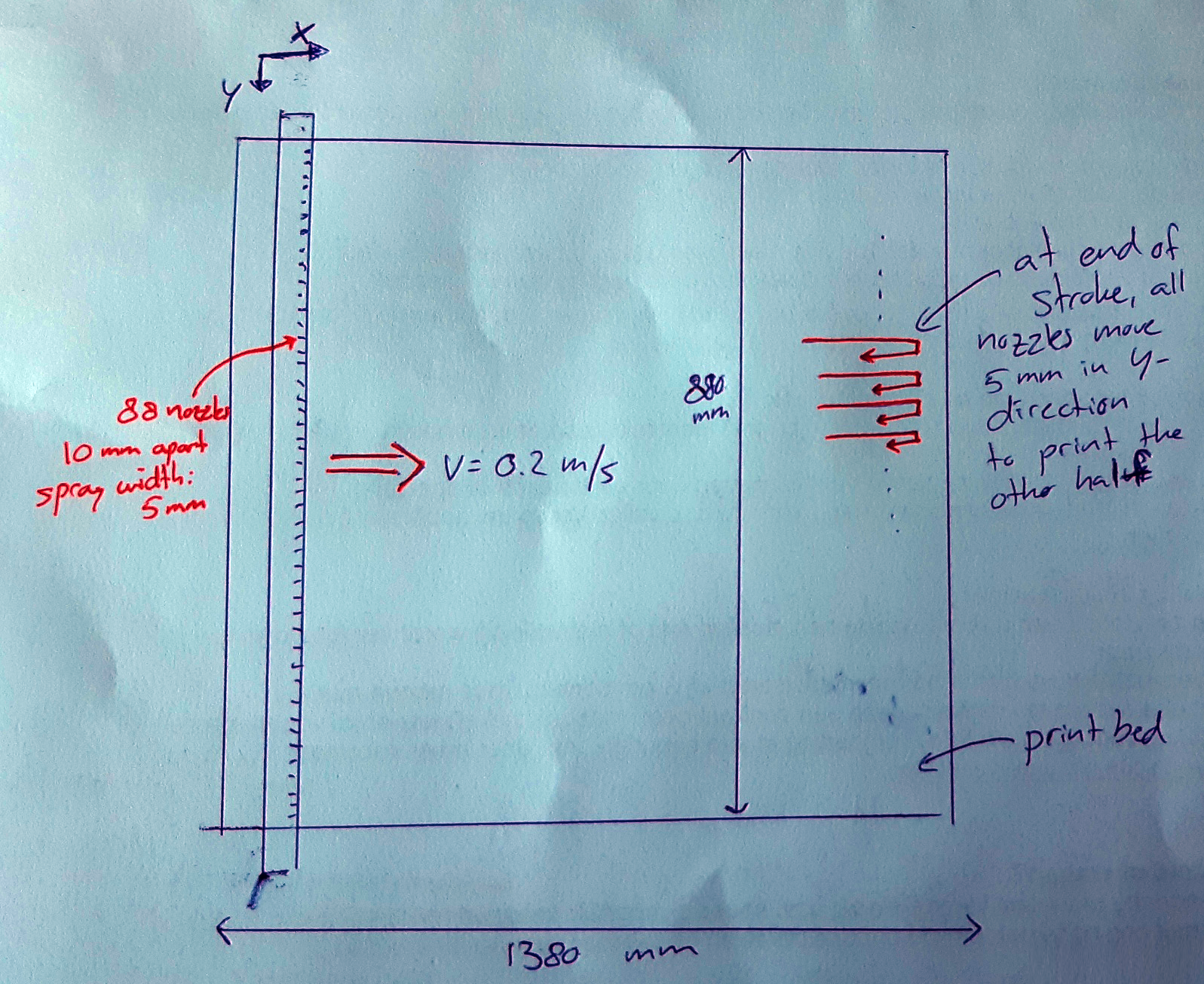
@dc42 please find here a rough sketch of the basic numbers on the printer.
So: 88 nozzles spread out over the Y axis, moving in X-direction. They are spaced 10mm apart, and spray a pattern of 5 mm wide. At the end of each stroke, the nozzles move 5 mm in Y-direction, and the other half of the print bed is covered on the back stroke (in the future this may be increased to 3.3mm Y-movement over 3 strokes).
Speed is ~0.2 m/s.
Thinking more about the X position update: 0.2mm is indeed quite extreme.. 1 mm resolution is more than plenty (even considering the possibility of 3.3mm spray size)
The X travel is actually 1380mm.
-
@alankilian I guess you mean M118: Send Message to Specific Target to send it to the second UART.
Yes this would be definitely an option. I can also imagine using SPI would be an option, but I don't see any reference to that in the G-code documentation, other then misusing M150: Set LED colours for controlling LEDs, which apparently uses SPI?
-
@arvest I presume you have your own GCode generator for this project, or perhaps a GCode post-processor that changes the G1 moves to add the P parameter for controlling the I/O ports and splitting longer moves up into smaller segments. If that's the case, then I think the simplest option would be to use the P parameter to pass a 10-bit X position to an Arduino or RPi Pico or similar controller, and have that controller operate the nozzles.
What voltage and current are needed to operate the nozzles?
Duet WiFi hardware designer and firmware engineer
Please do not ask me for Duet support via PM or email, use the forum
http://www.escher3d.com, https://miscsolutions.wordpress.com -
@dc42 good ideas here, thank you!
yes, we have our own slicer for this.
the voltage of the valves is 24V, current draw is about 70mA on average, peak current draw I have no idea, they are of the solenoid type. They will have there own power source, there will be a 3.3/5V control / communication signal to the valve controller board
So to summarize: you would use a separate valve controller (arduino + shift registers) to which you send the pattern for the current layer through M118 before starting the layer, and then using G1 + P parameter to pass the current position so the valve controller energizes the correct nozzles.
-
@arvest you can buy chips that take SPI input and can drive eight solenoid valves directly, for example this one https://www.digikey.co.uk/en/products/detail/stmicroelectronics/L9825TR/715854. You would need to check that the output clamping energy rating is not exceeded, which will depend on the inductance of the valves on on how often you turn them off.
-
@arvest said in challenge: controlling 88 output pins:
So to summarize: you would use a separate valve controller (arduino + shift registers) to which you send the pattern for the current layer through M118 before starting the layer
I guess it would be safer and faster, when the arduino part holds the pattern data on it's own SD-card. The duet would only control the moves and send a "line number" or a next line signal to the valve controller.
I'm almost tempted to say, a good old RAMPS-controller could do the trick without UART or SPI bottleneck. Everything is onboard, except the shift registers.