Duet3D Logo Duet3D
    • Tags
    • Documentation
    • Order
    • Register
    • Login

    Duet 3 Mini 5+ controlling Power Supply with SSR

    Scheduled Pinned Locked Moved Solved
    Duet Hardware and wiring
    4
    23
    777
    Loading More Posts
    • Oldest to Newest
    • Newest to Oldest
    • Most Votes
    Reply
    • Reply as topic
    Log in to reply
    This topic has been deleted. Only users with topic management privileges can see it.
    • jaclopundefined
      jaclop @dc42
      last edited by

      @dc42

      This is the ciruit with the transistor I used previously with the transistor, diode and resistor that can be seen in the previous photo:

      https://www.susa.net/wordpress/2012/06/raspberry-pi-relay-using-gpio/

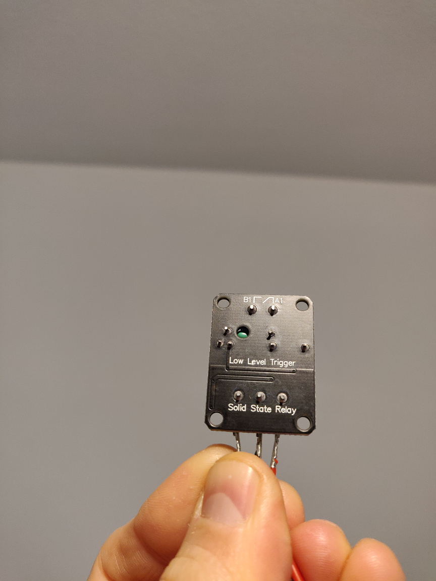
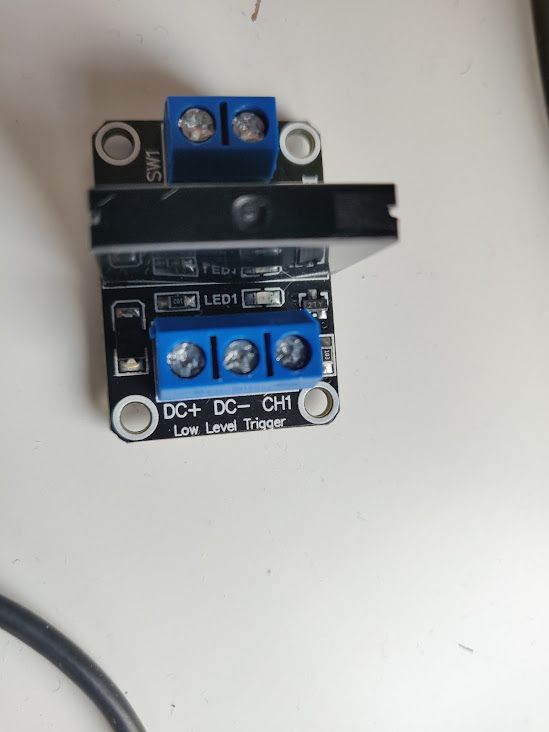
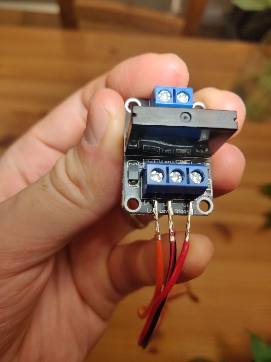
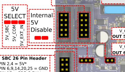
      Here are the labels of the board:

      ssr_module.jpg

      I guess I can directly connect 5V to DC+, PSON to DC- and 3.3V to CH1?

      Then when I use M80 and M81, I expect it will turn the relay on and off.

      achrnundefined dc42undefined 2 Replies Last reply Reply Quote 0
      • achrnundefined
        achrn @jaclop
        last edited by

        @jaclop As noted in the thread, the Duet board is designed to drive a SSR directly, and doesn't need the board, but with the board, I'd connect DC+ to 3.3V, DC- to GND, and the CH1 to io4.out. All three connections can be made on IO_4 header. This is making use of the fact that on a mini-5 IO_4 and ps_on are the same signal (but driven at different levels).

        If that doesn't work, DC+ to a 5V connection somewhere on the Duet board, DC- to a GND connection somewhere on the board and CH1 to the pson pin. I don't think you can get the 5V from the EXT 5V connector, because that's just for feeding 5V in, you'll need to get it from somewhere else (this is why this is my second choice).

        In either case you then need to test which polarity activates the SSR - ie whether you want M80 C"pson" or M80 C"!pson" (the board markings suggest probably pulling the output low will switch the SSR on, but it's more definitive to try both and see what happens).

        1 Reply Last reply Reply Quote 0
        • dc42undefined
          dc42 administrators @jaclop
          last edited by dc42

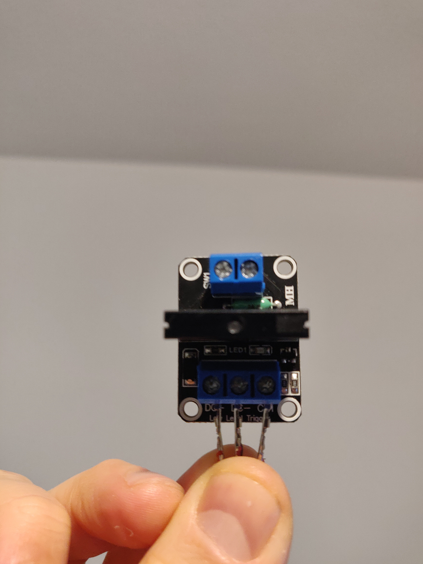
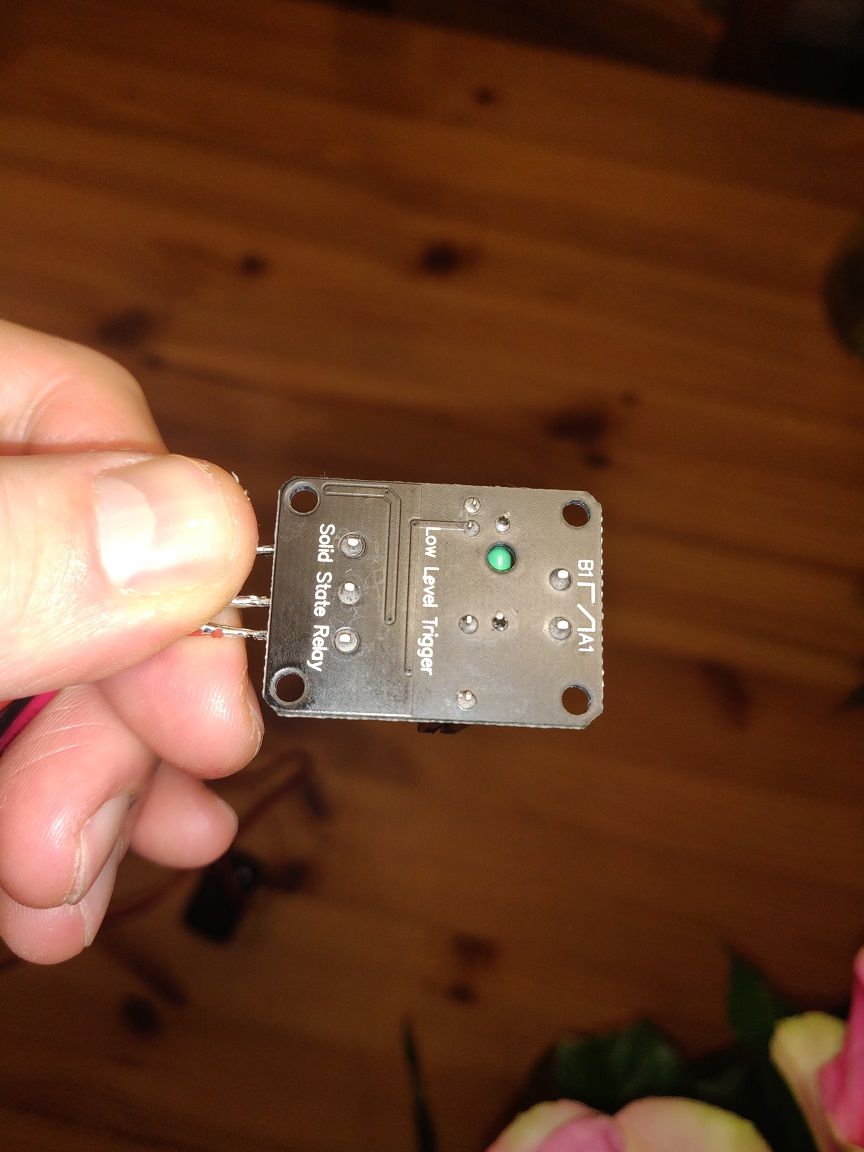
          @jaclop I can see that the board has a transistor driver on it. Please post a photo of the underside of that board, which may enable me to confirm my guess about how it should be connected.

          Duet WiFi hardware designer and firmware engineer
          Please do not ask me for Duet support via PM or email, use the forum
          http://www.escher3d.com, https://miscsolutions.wordpress.com

          jaclopundefined 1 Reply Last reply Reply Quote 0
          • jaclopundefined
            jaclop @dc42
            last edited by jaclop

            @dc42 ssr_bottom_2.png

            ssr_top_2.png

            Thanks for your help.

            dc42undefined 1 Reply Last reply Reply Quote 0
            • dc42undefined
              dc42 administrators @jaclop
              last edited by

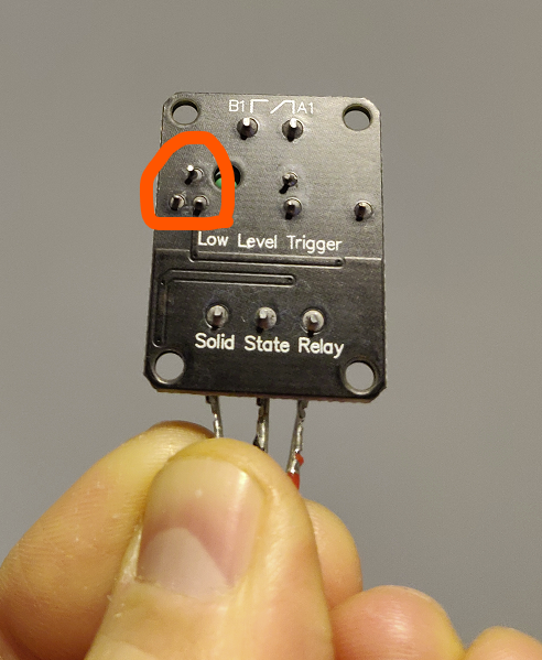
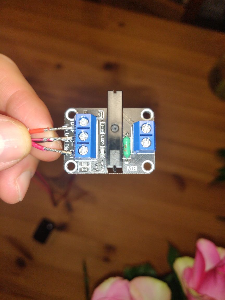
              @jaclop thanks. I can see the traces clearly on the underside, but not on the top side. So I still can't work out the schematic. Can you provide a photo of the top side with good lighting?

              I am a little concerned that there are high voltage connections close to low voltage connections on that board:
              09f8fdce-69a2-419d-a614-cbc756f00dd7-image.png

              Duet WiFi hardware designer and firmware engineer
              Please do not ask me for Duet support via PM or email, use the forum
              http://www.escher3d.com, https://miscsolutions.wordpress.com

              jaclopundefined 1 Reply Last reply Reply Quote 0
              • jaclopundefined
                jaclop @dc42
                last edited by

                @dc42 top_2.jpg top_1.jpg bottom.jpg Thanks again for your patience and help.

                dc42undefined 1 Reply Last reply Reply Quote 0
                • dc42undefined
                  dc42 administrators @jaclop
                  last edited by

                  @jaclop it looks to me that you can connect DC+ to +5V, DC- to GND, and CH1 to the PS_ON pin.

                  Duet WiFi hardware designer and firmware engineer
                  Please do not ask me for Duet support via PM or email, use the forum
                  http://www.escher3d.com, https://miscsolutions.wordpress.com

                  jaclopundefined 1 Reply Last reply Reply Quote 0
                  • jaclopundefined
                    jaclop @dc42
                    last edited by

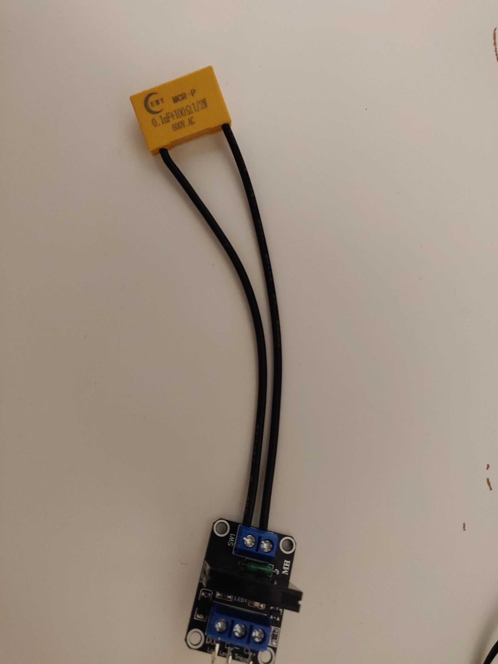
                    @dc42 Thanks. Is it also recommended to use a snubber like so between the two live wire contacts? In the past, I had to replace the SSR every 9 months or so which I'm guessing were failing due to voltage spikes.
                    snubber.jpg

                    dc42undefined 1 Reply Last reply Reply Quote 0
                    • dc42undefined
                      dc42 administrators @jaclop
                      last edited by dc42

                      @jaclop a snubber is usually only needed when the SSR drives an inductive load.

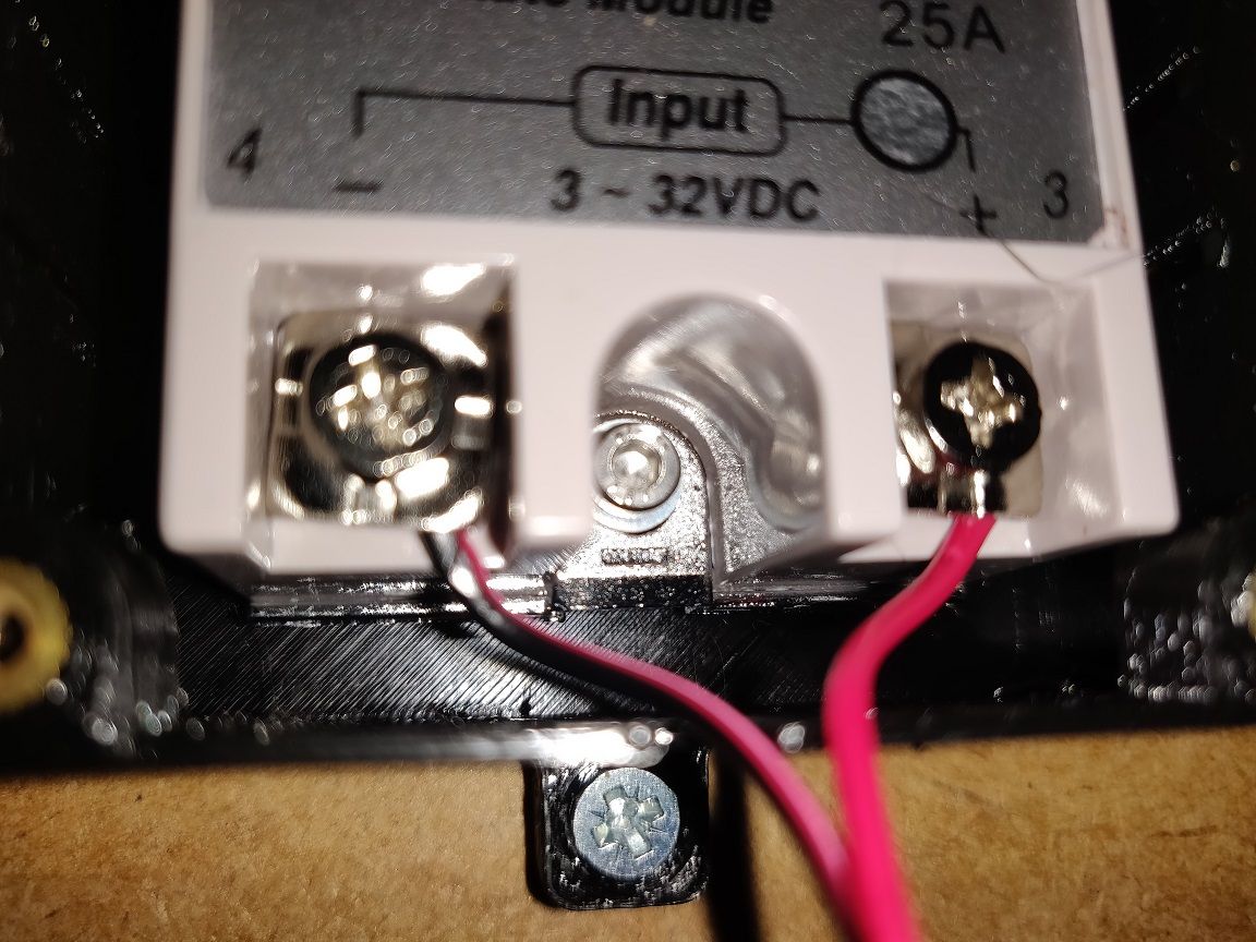
                      I suspect that the SSR may have failed because the surge current that the PSU draws when you start it up was too large. A larger SSR such as SSR25DA might be a better choice and can be driven directly from +5V (+ve control input) and PS_ON (-ve control input). Note, many Fotek SSR25DA listings on shopping sites are fakes.

                      Duet WiFi hardware designer and firmware engineer
                      Please do not ask me for Duet support via PM or email, use the forum
                      http://www.escher3d.com, https://miscsolutions.wordpress.com

                      jaclopundefined 1 Reply Last reply Reply Quote 0
                      • jaclopundefined
                        jaclop @dc42
                        last edited by

                        @dc42 Thanks. I could not get the SSR module working and due to the likelihood of future failures I have installed the SSR25DA but this is also not working.

                        I have M81 C"!pson" in my config.g file. I tried initially with i04.out and now have the positive input of the SSR25DA connected to 5V_EXT of IO_4 and the negative input of the SSR connected to pson. I have tried sending these commands: M80 C"!pson", M80 C"pson", M81 C"!pson", M81 C"pson, but the relay is not turning on the 12V PSU. My Duet Mini 5+ is being powered via the Micro USB using a 5V 2.5A power supply.

                        Am I doing something wrong or is there something I can try to troubleshoot this issue?

                        DIY-O-Sphereundefined 1 Reply Last reply Reply Quote 0
                        • DIY-O-Sphereundefined
                          DIY-O-Sphere @jaclop
                          last edited by

                          @jaclop
                          Which RRF version?

                          (UTC+1)

                          jaclopundefined 1 Reply Last reply Reply Quote 0
                          • jaclopundefined
                            jaclop @DIY-O-Sphere
                            last edited by

                            @DIY-O-Sphere

                            From Machine-Specific General Tab:

                            Board: Duet 3 Mini 5+ (Mini5plus)
                            Firmware: RepRapFirmware for Duet 3 Mini 5+ 3.3RC2 (2021-05-11)
                            Duet WiFi Server Version: 1.26

                            DIY-O-Sphereundefined 1 Reply Last reply Reply Quote 0
                            • DIY-O-Sphereundefined
                              DIY-O-Sphere @jaclop
                              last edited by DIY-O-Sphere

                              @jaclop
                              With RRF 3.3 you only need to add

                              M80
                              

                              at the end of config.g

                              (UTC+1)

                              jaclopundefined 1 Reply Last reply Reply Quote 0
                              • jaclopundefined
                                jaclop @DIY-O-Sphere
                                last edited by

                                @DIY-O-Sphere I added M80 to the end of the config file and applied the new configuration by running it but it did not activate the relay.

                                DIY-O-Sphereundefined 1 Reply Last reply Reply Quote 0
                                • DIY-O-Sphereundefined
                                  DIY-O-Sphere @jaclop
                                  last edited by

                                  @jaclop
                                  https://forum.duet3d.com/topic/19161/smart-remote-power-control?
                                  Maybe the wiring diagram helps. Have a look on the input side of the relay.
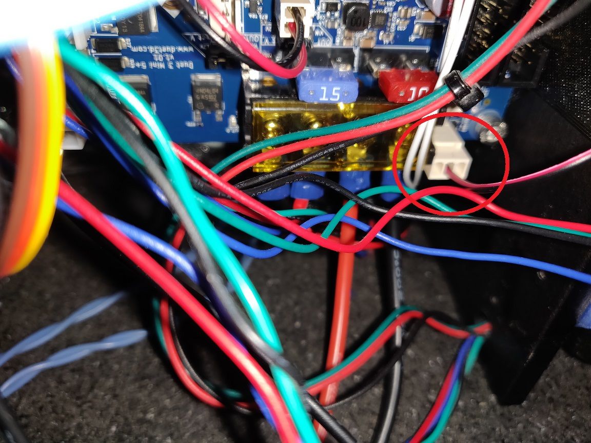
                                  You need the +5V and the middle pin of PS-On

                                  (UTC+1)

                                  jaclopundefined 1 Reply Last reply Reply Quote 0
                                  • jaclopundefined
                                    jaclop @DIY-O-Sphere
                                    last edited by jaclop

                                    @DIY-O-Sphere Re-checked my wiring but I still can't get the relay to activate.

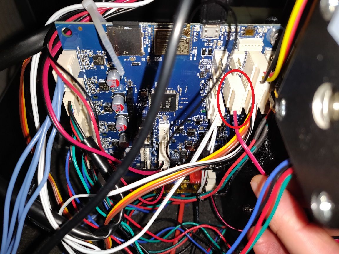
                                    This is the relay, the 5V_EXT connection and the PSON connection:

                                    relay_1.jpg
                                    5v_ext.jpg
                                    pson.jpg

                                    Is activating the relay using a GPIO pin an option? If so, how would I do that?

                                    DIY-O-Sphereundefined 2 Replies Last reply Reply Quote 0
                                    • DIY-O-Sphereundefined
                                      DIY-O-Sphere @jaclop
                                      last edited by DIY-O-Sphere

                                      @jaclop said in Duet 3 Mini 5+ controlling Power Supply with SSR:

                                      5V_EXT

                                      What is your setup of these two jumpers?
                                      400f7e3b-cb8b-47b4-8a1f-4b753161f500-grafik.png

                                      (UTC+1)

                                      1 Reply Last reply Reply Quote 0
                                      • DIY-O-Sphereundefined
                                        DIY-O-Sphere @jaclop
                                        last edited by

                                        @jaclop said in Duet 3 Mini 5+ controlling Power Supply with SSR:

                                        Is activating the relay using a GPIO pin an option?

                                        PS_ON should do the job....I guess you don't have the +5v voltage on the 5V_EXT pin

                                        (UTC+1)

                                        jaclopundefined 1 Reply Last reply Reply Quote 0
                                        • jaclopundefined
                                          jaclop @DIY-O-Sphere
                                          last edited by

                                          @DIY-O-Sphere It's working! I went to take a picture of my jumper set-up and accidentally "nudged" the cable connecting the 5V pin and PS_ON pin. My PSU turned on... I can now turn it on and off my PSU with M80 and M81 commands. I will double check the connections next time. Thanks a lot for your help, will mark this as resolved.

                                          1 Reply Last reply Reply Quote 0
                                          • dc42undefined dc42 marked this topic as a question
                                          • dc42undefined dc42 has marked this topic as solved
                                          • First post
                                            Last post
                                          Unless otherwise noted, all forum content is licensed under CC-BY-SA