5 bar scara on duet3!
-
@o_lampe said in 5 bar scara on duet3!:
studying silicone moulding with resin-printed moulds
BG, we are true brothers in mind
That's the reason why I had a short thread in the forum asking how many times it's possible to recycle ABS (or 3D printing material in general): I plan 3D printing molds and make injection molding of such things like the flex spline.
The first mold 3D printed, then inject something easy to fill in (PLA eg), then make a silicone mold of this, then injection mold something strong like aluminium or flexible like PP, maybe mixing with polycarbonate.
There are aluminium sorts which can be similar flexible as string steel.But I plan to make a postprocess CNC routing, because I expect that the teeth will not be perfect.
-
haha I was driving home from work contemplating if you could mass produce a plastic, lower cost harmonic drive for all the mechatronics nerds out there
") I feel like there's a need out there for a lowish cost, zero backlash reducer for robotics projects.
I feel like there's a need out there for a lowish cost, zero backlash reducer for robotics projects.Interesting to hear about the belt flex. Does that present as backlash or just lack of holding torque? Can you just increase the squish rate a bit to make up for that flexibility?
I keep going back to this guy as he's got a simple design and has demonstrated a large format scara arm printing really well. https://www.youtube.com/watch?v=2WuPUq7ELWI&ab_channel=KoalDesigns
I'm thinking about modifying this design a bit to use an HTD belt rather than an SLS printed belt and to also wrap this design around a 20mm rod which is what I'm using in my design. The integration with the belt reducer to the input of the harmonic drive is slick too. Once you realize that the stationary spline is just a modified pitch circle with a few teeth less than than the drive side it's pretty simple to design. The HTD tooth profile is simpler than GT2 as well.
I'm planning for a 9mm belt and some 3mm bearings that are 4mm wide stacked two tall mounted on 3mm shaft rather than screws. The height of this assembly should drive holding torque, which I don't want or need as I'd rather have the arms snap out of the way if they bump into anyone or anything
I'm hoping I can cut out the 90mm outside bearings and just have everything ride on the 20mm rod down the center as I have plenty of 20mm bearings and that's going to be way more rigid than bearings mounted into plastic. more to come on this design!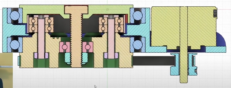
-
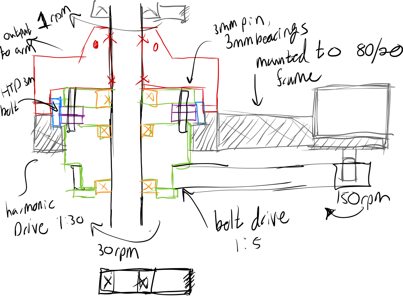
Here's a quick sketch I came up with for a design to try. I think I can use pairs of bearings to accomplish the same thing as as one big bearing on the outside. The 20mm rod in black down the center is the out put, and the red part from the harmonic drive is fixed to it. The green part is the input to the reducer and sits on bearings on the 20mm rod. The gray part is the fixed part of the reducer and is mounted to the 80/20 frame. I'll have to see how well I can float this part around the reducer. I suppose that's the potential hold up, but it's worth a go.
-
@michaelr123 a topic which you should imho add to the list to develop is an encoder for the actuators to detect skipped steps or alike. If you don't want to add it now, you should add space to your planning to have space to add it later.
-
I would love to add encoders to this and my duet powered voron at some point! I'm just waiting for the software and hardware to develop to the point where it's more or less a drop in upgrade with a bit of tuning. So far it seems like the project is in development stage and has just started to get dedicated hardware built for the duet 3 ecosystem like from LDO. Unfortunately I don’t have the time to dig into code and helping develop the project otherwise I would! I will probably gear the encoder directly to the 20mm shaft to make sure I’m getting right to the actual output rather than going through the harmonic drive. You’re getting the control theory side of my brain going again haha
To start off I’m going to get the dedicated drive unit for the extruder to cutdown the number of cables to just a power and signal cable. Managing a giant bundle of cables on my old machine was always a pain.
I’ll report back on the harmonic drive idea, but it’ll come down to how well it actually works on on the printer. The more I look the more I see a war going on between cycloidal drives and harmonic drives. I think it’s pretty well understood that fully printed flex spline cups don’t hold up well over time so you have to use some sort of flexible timing belt to perform this task.
Cycloidal boxes just use a pile of hardware, especially if you want multiple stages to smooth out the motion. I’ve seen what look to be robust solutions using both styles of gear boxes, so hopefully I can just pick one and make it work.
-
@michaelr123 said in 5 bar scara on duet3!:
fully printed flex spline cups don’t hold up well over time
I've bought used harmonic drives and even those flexsplines made out of steel have very damaged teeth, so I don't use them as templates.
Edit Feb 19: I thought about it: the teeth are very damaged, but I don't know how the harmonic drive was used. It depends on torque usage etc., so I don't have information about how long it can be used without replace. 3D printers will probably have low torque and robots with low payload also.
-
A gearbox- and robotarm design should allow easy access to the parts that wear out.
I've built a cycloidal drive with dual disks a few years back (not my design, though)
The dual disks eliminated the vibrations caused by the excenter drive path of the rotor.
I'm not sure how much a harmonic drive vibrates and if it's possible to have two rotors/flex-splines with a 180° excenter?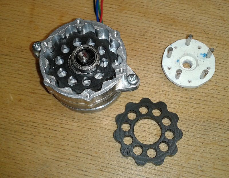
@JoergS5 A moulded part will show the imperfections of the FDM-printer (rounded corners, layer-gaps). With ABS-moulds you have the chance to smooth the surface with acetone, but will it still be accurate afterwards?
That's why I'm interested in resin printed moulds. I hope, they will need much less manual labour.
My Lychee resin slicer also has options to build a negative form from any .stl file and split it in halfes. Pretty easy to build moulds. -
I did a little looking into steppers with encoders and the HCL1. I'd consider it for my voron, but I'd also have to upgrade that machine to a duet 3 from a duet 2 along with the motors and drivers. That's a pretty pricey upgrade for a home built machine I'm pretty happy with lol.
I'm not sure how much of a difference closed loops motors would have for this giant scara arm as I'm gearing it up so much for the resolution. I don't think a drop in motor encoder would correct the issues I'll see at the end effector through all the gears. Also, do we know if the closed loop control works in non-cartesian work spaces?
This is what I'd go with for a motor along with the HCL1's (US source).
-
@michaelr123 the reasoning for my encoder recommendation is not for closed loop and to rescue from lost steps, but to have a reference angle.
I need to go a bit into the details:
"normal" kinematics like CoreXY and Cartesian need only relative positions for the position information. If the endstop reference is inexact, this is no problem, because if you have e.g. 3 mm wrong position, this is no problem. The endstops triggers and you and your firmware think it's at 0 position, but in truth you're at 3, e.g. But this is no problem, because your print object will be 3 mm off, but the whole object, so that's no problem.
With delta, scara, robot, parallel Scara, Tripteron etc. this is different: here not only the relative position, but also the absolute position is important. Because kinematic calculation includes trigonometric and other algorithms and 3 mm off means wrong actuator angle calculations for this position and you'll get incorrect results. The calculation is for 0, but the realitiy is 3 for your physical reality. Positioning will be wrong and your straight lines will be curved.
So the main reason to recommend an encoder is to get the correct 0 degree (or other fixed) reference every time, and to be able to check it between layers.
An absolute encoder is IMHO better than a relative encoder for this use case, because relative encoders are often based on methods like hall effect which are inexact on their own.
For this use case there are different methods to assure angle exactness and encoder is only one method. You can assure by laser path through all hinges and arms if you like. Another possibility is to set specific endpoint(s) as reference and assure that moving there gets the correct result every time, by triggering it or by camera or other means.
-
all good points on more complicated motion systems. That's the kind of thing you don't figure out until you're actually working with it

The nice thing with this design is that I can adjust the arm lengths a bit to dial in the arm lengths to be as close as I can get them with a tape measure.
I'll post a picture of my design tonight, but I'm really happy with how it's turned out so far. It's based on a 75t HTD 3m belt. Zero back lash as far as I can tell so far. I ended up using 5mm bearings inside just riding on bolts to start, but I'm really happy with the results so far. The stationary gear is just free-floating without being fixed to a piece of 80/20 yet. I may add a built in bearing using 5mm ball bearings to connect the output side to the input. This might not be necesary once it's connected via pillow blocks and aluminum extrusion.

I found this guy who printed a harmonic drive that used a printed bearing raceway that looks really solid. He's printing the flexspline with a .25mm nozzle and dialing in his settings for PETG. I'm curious to try it. He's using it for very slow speed and low torque applications as drives for astronomy.
https://www.printables.com/de/model/309144-791-harmonicdrive-for-keen-one-eq/comments -
@michaelr123 said in 5 bar scara on duet3!:
points on more complicated motion systems
I want to offer you a buffet, and you choose your personal caviar from it
") You don't need to eat all you can...
You don't need to eat all you can...Thanks for the link, this harmonic drive looks promising. It also supports my theory that having more balls at the wave generator is better than only 2 like some design on thingiverse have.
I already found several interesting homepages about astronomy, they are very creative people from whom one can learn a lot for precision mechanics.
-
@michaelr123 said in 5 bar scara on duet3!:
dial in the arm lengths to be as close as I can get them with a tape measure
When your mechanical construction is precise enough, you can go the other round, measuring the endpoints and calculating back how long the elements are and set the configuration accordingly.
-
@michaelr123 I tried to understand how your harmonic drive works, so please correct me where I'm wrong:
- The belt has contact with two involute gears
- One involute gear is fixed, the other is the output gear
- They have a different tooth-count which determines the gear ratio
What's the tooth count of them and is it important how many teeth the belt has?
The gear with the bigger tooth count has a wider diameter and that puts some stress to the belt? You need good meshing teeth on both gears, for being backlash free, I guess.I'm just asking, because based on my assumptions, I may have a solution in mind, where despite different tooth count the diameter of both gears is identic.
-
 undefined oliof referenced this topic
-
@michaelr123 that would be @koaldesigns but they are busy with life AFAIK.
-
@o_lampe the commercial HDUA series has a flexspline with common teeth count and the circular splines with +0 and +2 teeth. And a double row ball bearing wave generator.
-
@JoergS5
I thought of something different:
instead of using a belt to connect the involute gears, use dual beveled gears which can rotate freely on a concentric rotor.
That way the fixed side and the output side can have different module and teeth count. (They don't have to share the pitch of the belt)I tried to make a quick sketch, but couldn't draw a beveled involute gear.
-
@o_lampe I would say this is similar to planetary gear and has backlash, but it is worth a try. In general, it would be good to compare all those gear ideas by measuring the precision they can achieve. There is one new gear idea of company harmonicdrive which can be added to the list (I currently don't find the link*)).
*) found it: Abacus: https://spectrum.ieee.org/sri-demonstrates-abacus-rotary-transmission
-
@JoergS5 said in 5 bar scara on duet3!:
this is similar to planetary gear and has backlash
I chose beveled gears, because the gap between the two outer rings can be adjusted to eliminate backlash.
If I had a real usecase, I'd like to print experimental gearboxes from resin. Maybe start with a small version like the orbiter? -
Check out split ring planetary gears: https://www.youtube.com/watch?v=4gkbb2CBzQI&ab_channel=LeviJanssen
When I was fresh out of engineering school I was obsessed with this design however, they never ran well and were complicated to design. There isn't much info on them and there are very gear ratios that line up properly (something about everything being multiples of each other).
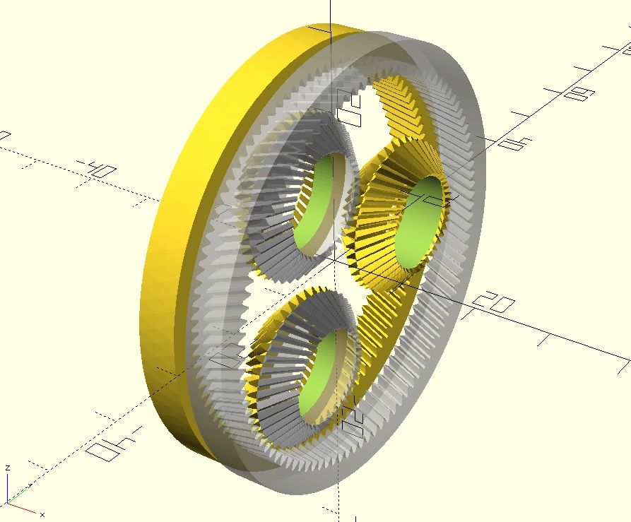
So far I'm a lot happier with the real-world performance from flex-splines. @JoergS5 - I agree with you you on having an elliptical driver rather than just a few sets of bearings. The HTD belt design I came up with works great as is, but I'm sure it would run better with an elliptical driver. I printed that 79:1 driver in PETG and was fairly impressed. It may need a slightly larger elliptical drive as the flex spline doesn't mesh tight enough to the ring gear as is. One other thing I don't like about this design is how tough it is to install the ball bearings and it's loud. The belt design is completely silent.
I'm going to play around with a fully printed flex spline design this weekend with a lower gear ratio as 79:1 plus a belt reduction is overkill. I'm trying to eliminate the HTD belt if possible as the they're pricey and you can't get them in many sizes both for tooth count and width.
-
yep you've got it. It's a split ring design where one half matches the tooth count of the belt and the other half is +2 teeth. So for a 75t 3m HTD belt it's 75t on one half and 77t on the other. the input is the elliptical part (what @JoergS5 and I are going back and forth about bearings vs. full ellipse). The tolerance needs to be fairly tight to get zero backlash, but also needs to allow for the belt to "stretch" a tooth so the 77t side can precess +2 teeth forward. I just drew it up and it worked well on my first attempt so I guess it's not too tough to dial in?
Either of the two halves can be the output or fixed (that might be incorrect technically, but just from playing with it seems like that's true). Also remember for the belted design they're not involute gear teeth, but HTD pulley teeth.