6 Axis linear Delta
-
Hello @dc42,
can you add a new kinematics type number for a six axis Delta?
"Tell me the name of your kinematics and ask me (dc42) to allocate a kinematics type number for it, via the Duet3d forum. The kinematics type number will be the K parameter in the M669 command." Duet3d/Github
Best regards
Tim -
Hello,
What does ...
fsquare(Q) //Line 111 LinearDeltaKinematics.cpp.. mean?
void LinearDeltaKinematics::Recalc() noexcept { towerX[DELTA_A_AXIS] = -(radius * cosf((30 + angleCorrections[DELTA_A_AXIS]) * DegreesToRadians)); towerY[DELTA_A_AXIS] = -(radius * sinf((30 + angleCorrections[DELTA_A_AXIS]) * DegreesToRadians)); towerX[DELTA_B_AXIS] = +(radius * cosf((30 - angleCorrections[DELTA_B_AXIS]) * DegreesToRadians)); towerY[DELTA_B_AXIS] = -(radius * sinf((30 - angleCorrections[DELTA_B_AXIS]) * DegreesToRadians)); towerX[DELTA_C_AXIS] = -(radius * sinf(angleCorrections[DELTA_C_AXIS] * DegreesToRadians)); towerY[DELTA_C_AXIS] = +(radius * cosf(angleCorrections[DELTA_C_AXIS] * DegreesToRadians)); Xbc = towerX[DELTA_C_AXIS] - towerX[DELTA_B_AXIS]; Xca = towerX[DELTA_A_AXIS] - towerX[DELTA_C_AXIS]; Xab = towerX[DELTA_B_AXIS] - towerX[DELTA_A_AXIS]; Ybc = towerY[DELTA_C_AXIS] - towerY[DELTA_B_AXIS]; Yca = towerY[DELTA_A_AXIS] - towerY[DELTA_C_AXIS]; Yab = towerY[DELTA_B_AXIS] - towerY[DELTA_A_AXIS]; Q = (Xab * towerY[DELTA_C_AXIS] + Xca * towerY[DELTA_B_AXIS] + Xbc * towerY[DELTA_A_AXIS]) * 2; Q2 = fsquare(Q); -
Hello,
next question, is radius (Line 93: LinearDeltaKinamtics.h) the same like the R parameter from the config. file( M665 with L### R### H### B### X### Y### Z###)
// Core parameters size_t numTowers; float diagonals[MaxTowers]; // The diagonal rod lengths -> float radius; // The nominal delta radius, before any fine tuning of tower positions float angleCorrections[UsualNumTowers]; // Tower position corrections for the first 3 axes float endstopAdjustments[MaxTowers]; // How much above or below the ideal position each endstop is float printRadius; float homedHeight; float xTilt, yTilt; -
@tkln said in 6 Axis linear Delta:
Hello @dc42,
can you add a new kinematics type number for a six axis Delta?
"Tell me the name of your kinematics and ask me (dc42) to allocate a kinematics type number for it, via the Duet3d forum. The kinematics type number will be the K parameter in the M669 command." Duet3d/Github
Best regards
TimI have reserved type code 14 for your kinematics in RRF 3.5 and later.
-
@tkln fsquare(x) is a function declared in RRFLibraries that returns the square of its operand. So fsquare(Q) is the same as Q * Q.
The 'radius' variable is initialised from the M665 R parameter.
-
@dc42 thanks for the fast reply
- Is there a reason why the file cannot be found?
I used vscode with the clone file from github
#include math/deviaion.h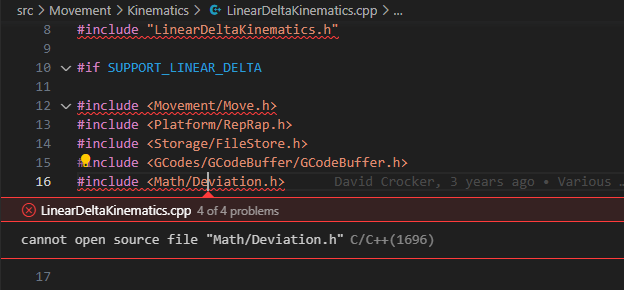
-> My next step is: define the positions of the six actuators relative to the base.
These are the corners of my tower
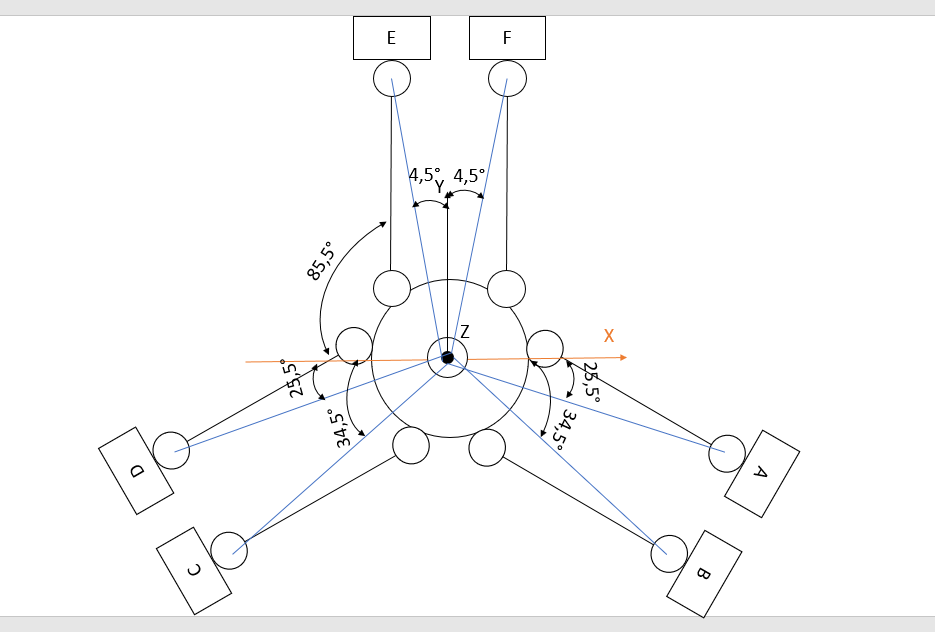
That would be the tower positions.
	towerX[DELTA_A_AXIS] = -(radius * cosf((25,5 + angleCorrections[DELTA_A_AXIS]) * DegreesToRadians));
	towerY[DELTA_A_AXIS] = -(radius * sinf((25,5 + angleCorrections[DELTA_A_AXIS]) * DegreesToRadians));
	towerX[DELTA_B_AXIS] = -(radius * cosf((34,5 + angleCorrections[DELTA_B_AXIS]) * DegreesToRadians));
	towerY[DELTA_B_AXIS] = -(radius * sinf((34,5 + angleCorrections[DELTA_B_AXIS]) * DegreesToRadians));
	towerX[DELTA_C_AXIS] = -(radius * cosf((34,5 - angleCorrections[DELTA_C_AXIS]) * DegreesToRadians));
	towerY[DELTA_C_AXIS] = +(radius * sinf((34,5 - angleCorrections[DELTA_C_AXIS]) * DegreesToRadians));
	towerX[DELTA_D_AXIS] = -(radius * cosf((25,5 - angleCorrections[DELTA_D_AXIS]) * DegreesToRadians));
	towerY[DELTA_D_AXIS] = +(radius * sinf((25,5 - angleCorrections[DELTA_D_AXIS]) * DegreesToRadians));
	towerX[DELTA_E_AXIS] = +(radius * cosf((4,5 - angleCorrections[DELTA_E_AXIS]) * DegreesToRadians));
	towerY[DELTA_E_AXIS] = +(radius * sinf((4,5 - angleCorrections[DELTA_E_AXIS]) * DegreesToRadians));
	towerX[DELTA_F_AXIS] = -(radius * cosf((4,5 + angleCorrections[DELTA_F_AXIS]) * DegreesToRadians));
	towerY[DELTA_F_AXIS] = +(radius * sinf((4,5 + angleCorrections[DELTA_F_AXIS]) * DegreesToRadians));
Questions about the tower positions
2. Or do I have to dial +-85.5° for Tower E and F?
3. When is the angleCorrections[DELTA_A_AXIS] positive and when is it negative?
4. From the LinearDeltaKinematics.cpp, the tower position is like in the picture, isn't it?towerX[DELTA_A_AXIS] = -(radius * cosf((30 + angleCorrections[DELTA_A_AXIS]) * DegreesToRadians)); towerY[DELTA_A_AXIS] = -(radius * sinf((30 + angleCorrections[DELTA_A_AXIS]) * DegreesToRadians)); towerX[DELTA_B_AXIS] = +(radius * cosf((30 - angleCorrections[DELTA_B_AXIS]) * DegreesToRadians)); towerY[DELTA_B_AXIS] = -(radius * sinf((30 - angleCorrections[DELTA_B_AXIS]) * DegreesToRadians)); towerX[DELTA_C_AXIS] = -(radius * sinf(angleCorrections[DELTA_C_AXIS] * DegreesToRadians)); towerY[DELTA_C_AXIS] = +(radius * cosf(angleCorrections[DELTA_C_AXIS] * DegreesToRadians));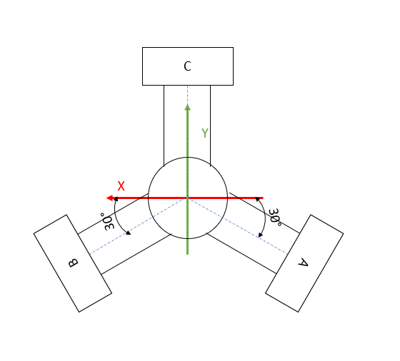
- What values do these variables represent?
float Xbc, Xca, Xab, Ybc, Yca, Yab;I don't quite understand what coordinates are calculated with it.
	Xbc = towerX[DELTA_C_AXIS] - towerX[DELTA_B_AXIS];
	Xca = towerX[DELTA_A_AXIS] - towerX[DELTA_C_AXIS];
	Xab = towerX[DELTA_B_AXIS] - towerX[DELTA_A_AXIS];
	Ybc = towerY[DELTA_C_AXIS] - towerY[DELTA_B_AXIS];
	Yca = towerY[DELTA_A_AXIS] - towerY[DELTA_C_AXIS];
	Yab = towerY[DELTA_B_AXIS] - towerY[DELTA_A_AXIS];
I am grateful for every comment, criticism, help and idea.
- Is there a reason why the file cannot be found?
-
- File Math/Deviation.h is in the RRFLibraries project, which is in the include path when compiling RRF under Eclipse.
2,3. I don't know, I haven't studied that kinematics. You have the additional complication that the effector can rotate; so the usual equations for linear delta kinematics don't apply. Your kinematics is akin to a Stewart platform, except that instead of changing the lengths of the rods you are changing the anchor positions.
-
Yes.
-
Xbc = towerX[DELTA_C_AXIS] - towerX[DELTA_B_AXIS]sets Xbc to the difference in the X coordinates of the C tower and the B tower.
-
@dc42
So the kinematics calculation is completed and tested with Matlab, so far everything works. Now I want to implement the refraction in the firmware. For this I would like to cut out everything unnecessary from the LinearDeltaKinematics.cpp. So that I can enter x,y,z and the three rotation angles u,w,v and the machine moves. Is it correct that I can delete everything in LinearDeltaKinematics.cpp from line 245 or does everything have to remain in place for it to work? -
@tkln you could write stub functions to replace the ones after line 245 in LinearDeltaKinematics.cpp.
-
@dc42
So is it correct that from line 245 everything else can be commented out? Or is any of this required for the Reprap firmware to work if I just want to test motion without any calibration? -
I have several questions about the LinearDeltaKinematics.h file.
- Is it enough to change these things in this file UsualNumTowers and "Axis names used internally" + "Derived values" for my kinematic calculation?
static constexpr size_t UsualNumTowers = 3;
-> static constexpr size_t UsualNumTowers = 6;```
// Axis names used internally static constexpr size_t DELTA_A_AXIS = 0; static constexpr size_t DELTA_B_AXIS = 1; static constexpr size_t DELTA_C_AXIS = 2; static constexpr size_t DELTA_D_AXIS = 3; static constexpr size_t DELTA_E_AXIS = 4; static constexpr size_t DELTA_F_AXIS = 5;- Can i use SUPPORT_LINEAR_DELTA for my Six Axis Delta or do I have to change something there?
-
@dc42
Is it correct that machinePos[X_AXIS], machinePos[Y_AXIS], machinePos[Z_AXIS] calculates the Z coordinate of the linear slides?// Calculate the Cartesian coordinates from the motor coordinates void LinearDeltaKinematics::ForwardTransform(float Ha, float Hb, float Hc, float machinePos[XYZ_AXES]) const noexcept { // Calculate RSUT such that x = (Uz + S)/Q, y = -(Rz + T)/Q const float R = ((Xbc * Ha) + (Xca * Hb) + (Xab * Hc)) * 2; const float U = ((Ybc * Ha) + (Yca * Hb) + (Yab * Hc)) * 2; // Note, Ka + Kb + Kc = 0 so we could calculate just two of them const float Ka = coreKa + (fsquare(Hc) - fsquare(Hb)), Kb = coreKb + (fsquare(Ha) - fsquare(Hc)), Kc = coreKc + (fsquare(Hb) - fsquare(Ha)); const float S = Ka * towerY[DELTA_A_AXIS] + Kb * towerY[DELTA_B_AXIS] + Kc * towerY[DELTA_C_AXIS]; const float T = Ka * towerX[DELTA_A_AXIS] + Kb * towerX[DELTA_B_AXIS] + Kc * towerX[DELTA_C_AXIS]; const float A = fsquare(U) + fsquare(R) + Q2; const float minusHalfB = Q2 * Ha + Q * (U * towerX[DELTA_A_AXIS] - R * towerY[DELTA_A_AXIS]) - (R * T + U * S); const float C = fsquare(towerX[DELTA_A_AXIS] * Q - S) + fsquare(towerY[DELTA_A_AXIS] * Q + T) + (fsquare(Ha) - D2[DELTA_A_AXIS]) * Q2; const float z = (minusHalfB - fastSqrtf(fsquare(minusHalfB) - A * C)) / A; machinePos[X_AXIS] = (U * z + S) / Q; machinePos[Y_AXIS] = -(R * z + T) / Q; machinePos[Z_AXIS] = z - ((machinePos[X_AXIS] * xTilt) + (machinePos[Y_AXIS] * yTilt)); -
@tkln, I suggest you create a new kinematics file and use the new type number that I allocated for you. Unless your kinematics uses the same inverse kinematics as for a linear delta, you will need to enable segmentation. This is done by supplying default segmentation parameters when calling the base class constructor. See the RotaryDeltaKinematics files for example.
-
@dc42
I understand that would be the best option for clean and orderly documentation.
I would like to test my kinematics first and for that I would like to have only the most necessary things in the kinematics file and keep everything as short as possible. For that I would like to not add something like autocalibration etc. in the first place. -
@dc42
Ah the tip with the Rotary Delta helped me, thanks. Now I can compare a bit. -
@dc42
Okay, last question for today, it's getting late in Germany
Sorry for all the questions but I'm so excited to finally see the machines in action.
If I just want to test the 6-axis kinematics first, is it possible to create 6 axes with "Creating additional axes" and feed them with motor positions? I would then convert a Gcode with my 6-axis kinematics and then give the values to the Duet.
Is there a command that I do not control the ABCDEF axes using Cartesian coordinates (X10 Y10 Z5) but directly using steps (A5 B10 C10 D10 E100 F10)?
Is there anything against it? -
@tkln said in 6 Axis linear Delta:
Is there a command that I do not control the ABCDEF axes using Cartesian coordinates (X10 Y10 Z5) but directly using steps (A5 B10 C10 D10 E100 F10)?
I guess by defining them as rotatry axes and setting a propper steps/degree value, you can mimic steps . (eg. with 16 microsteps it would be 'M92 A16')
-
@tkln
Solution: https://forum.duet3d.com/post/315912