6 Axis linear Delta
-
Hello @dc42,
can you add a new kinematics type number for a six axis Delta?
"Tell me the name of your kinematics and ask me (dc42) to allocate a kinematics type number for it, via the Duet3d forum. The kinematics type number will be the K parameter in the M669 command." Duet3d/Github
Best regards
Tim -
Hello,
What does ...
fsquare(Q) //Line 111 LinearDeltaKinematics.cpp.. mean?
void LinearDeltaKinematics::Recalc() noexcept { towerX[DELTA_A_AXIS] = -(radius * cosf((30 + angleCorrections[DELTA_A_AXIS]) * DegreesToRadians)); towerY[DELTA_A_AXIS] = -(radius * sinf((30 + angleCorrections[DELTA_A_AXIS]) * DegreesToRadians)); towerX[DELTA_B_AXIS] = +(radius * cosf((30 - angleCorrections[DELTA_B_AXIS]) * DegreesToRadians)); towerY[DELTA_B_AXIS] = -(radius * sinf((30 - angleCorrections[DELTA_B_AXIS]) * DegreesToRadians)); towerX[DELTA_C_AXIS] = -(radius * sinf(angleCorrections[DELTA_C_AXIS] * DegreesToRadians)); towerY[DELTA_C_AXIS] = +(radius * cosf(angleCorrections[DELTA_C_AXIS] * DegreesToRadians)); Xbc = towerX[DELTA_C_AXIS] - towerX[DELTA_B_AXIS]; Xca = towerX[DELTA_A_AXIS] - towerX[DELTA_C_AXIS]; Xab = towerX[DELTA_B_AXIS] - towerX[DELTA_A_AXIS]; Ybc = towerY[DELTA_C_AXIS] - towerY[DELTA_B_AXIS]; Yca = towerY[DELTA_A_AXIS] - towerY[DELTA_C_AXIS]; Yab = towerY[DELTA_B_AXIS] - towerY[DELTA_A_AXIS]; Q = (Xab * towerY[DELTA_C_AXIS] + Xca * towerY[DELTA_B_AXIS] + Xbc * towerY[DELTA_A_AXIS]) * 2; Q2 = fsquare(Q); -
Hello,
next question, is radius (Line 93: LinearDeltaKinamtics.h) the same like the R parameter from the config. file( M665 with L### R### H### B### X### Y### Z###)
// Core parameters size_t numTowers; float diagonals[MaxTowers]; // The diagonal rod lengths -> float radius; // The nominal delta radius, before any fine tuning of tower positions float angleCorrections[UsualNumTowers]; // Tower position corrections for the first 3 axes float endstopAdjustments[MaxTowers]; // How much above or below the ideal position each endstop is float printRadius; float homedHeight; float xTilt, yTilt; -
@tkln said in 6 Axis linear Delta:
Hello @dc42,
can you add a new kinematics type number for a six axis Delta?
"Tell me the name of your kinematics and ask me (dc42) to allocate a kinematics type number for it, via the Duet3d forum. The kinematics type number will be the K parameter in the M669 command." Duet3d/Github
Best regards
TimI have reserved type code 14 for your kinematics in RRF 3.5 and later.
Duet WiFi hardware designer and firmware engineer
Please do not ask me for Duet support via PM or email, use the forum
http://www.escher3d.com, https://miscsolutions.wordpress.com -
@tkln fsquare(x) is a function declared in RRFLibraries that returns the square of its operand. So fsquare(Q) is the same as Q * Q.
The 'radius' variable is initialised from the M665 R parameter.
-
@dc42 thanks for the fast reply
- Is there a reason why the file cannot be found?
I used vscode with the clone file from github
#include math/deviaion.h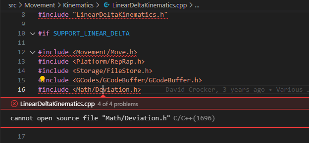
-> My next step is: define the positions of the six actuators relative to the base.
These are the corners of my tower
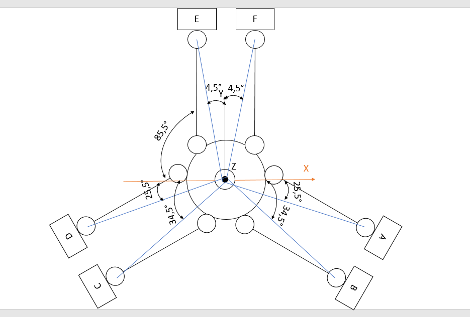
That would be the tower positions.
	towerX[DELTA_A_AXIS] = -(radius * cosf((25,5 + angleCorrections[DELTA_A_AXIS]) * DegreesToRadians));
	towerY[DELTA_A_AXIS] = -(radius * sinf((25,5 + angleCorrections[DELTA_A_AXIS]) * DegreesToRadians));
	towerX[DELTA_B_AXIS] = -(radius * cosf((34,5 + angleCorrections[DELTA_B_AXIS]) * DegreesToRadians));
	towerY[DELTA_B_AXIS] = -(radius * sinf((34,5 + angleCorrections[DELTA_B_AXIS]) * DegreesToRadians));
	towerX[DELTA_C_AXIS] = -(radius * cosf((34,5 - angleCorrections[DELTA_C_AXIS]) * DegreesToRadians));
	towerY[DELTA_C_AXIS] = +(radius * sinf((34,5 - angleCorrections[DELTA_C_AXIS]) * DegreesToRadians));
	towerX[DELTA_D_AXIS] = -(radius * cosf((25,5 - angleCorrections[DELTA_D_AXIS]) * DegreesToRadians));
	towerY[DELTA_D_AXIS] = +(radius * sinf((25,5 - angleCorrections[DELTA_D_AXIS]) * DegreesToRadians));
	towerX[DELTA_E_AXIS] = +(radius * cosf((4,5 - angleCorrections[DELTA_E_AXIS]) * DegreesToRadians));
	towerY[DELTA_E_AXIS] = +(radius * sinf((4,5 - angleCorrections[DELTA_E_AXIS]) * DegreesToRadians));
	towerX[DELTA_F_AXIS] = -(radius * cosf((4,5 + angleCorrections[DELTA_F_AXIS]) * DegreesToRadians));
	towerY[DELTA_F_AXIS] = +(radius * sinf((4,5 + angleCorrections[DELTA_F_AXIS]) * DegreesToRadians));
Questions about the tower positions
2. Or do I have to dial +-85.5° for Tower E and F?
3. When is the angleCorrections[DELTA_A_AXIS] positive and when is it negative?
4. From the LinearDeltaKinematics.cpp, the tower position is like in the picture, isn't it?towerX[DELTA_A_AXIS] = -(radius * cosf((30 + angleCorrections[DELTA_A_AXIS]) * DegreesToRadians)); towerY[DELTA_A_AXIS] = -(radius * sinf((30 + angleCorrections[DELTA_A_AXIS]) * DegreesToRadians)); towerX[DELTA_B_AXIS] = +(radius * cosf((30 - angleCorrections[DELTA_B_AXIS]) * DegreesToRadians)); towerY[DELTA_B_AXIS] = -(radius * sinf((30 - angleCorrections[DELTA_B_AXIS]) * DegreesToRadians)); towerX[DELTA_C_AXIS] = -(radius * sinf(angleCorrections[DELTA_C_AXIS] * DegreesToRadians)); towerY[DELTA_C_AXIS] = +(radius * cosf(angleCorrections[DELTA_C_AXIS] * DegreesToRadians));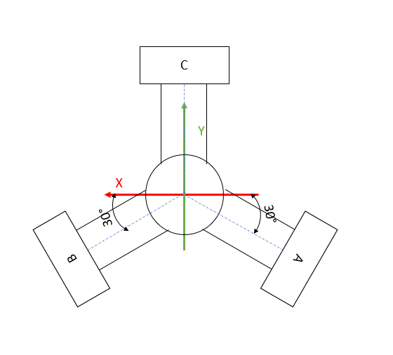
- What values do these variables represent?
float Xbc, Xca, Xab, Ybc, Yca, Yab;I don't quite understand what coordinates are calculated with it.
	Xbc = towerX[DELTA_C_AXIS] - towerX[DELTA_B_AXIS];
	Xca = towerX[DELTA_A_AXIS] - towerX[DELTA_C_AXIS];
	Xab = towerX[DELTA_B_AXIS] - towerX[DELTA_A_AXIS];
	Ybc = towerY[DELTA_C_AXIS] - towerY[DELTA_B_AXIS];
	Yca = towerY[DELTA_A_AXIS] - towerY[DELTA_C_AXIS];
	Yab = towerY[DELTA_B_AXIS] - towerY[DELTA_A_AXIS];
I am grateful for every comment, criticism, help and idea.
- Is there a reason why the file cannot be found?
-
- File Math/Deviation.h is in the RRFLibraries project, which is in the include path when compiling RRF under Eclipse.
2,3. I don't know, I haven't studied that kinematics. You have the additional complication that the effector can rotate; so the usual equations for linear delta kinematics don't apply. Your kinematics is akin to a Stewart platform, except that instead of changing the lengths of the rods you are changing the anchor positions.
-
Yes.
-
Xbc = towerX[DELTA_C_AXIS] - towerX[DELTA_B_AXIS]sets Xbc to the difference in the X coordinates of the C tower and the B tower.
-
@dc42
So the kinematics calculation is completed and tested with Matlab, so far everything works. Now I want to implement the refraction in the firmware. For this I would like to cut out everything unnecessary from the LinearDeltaKinematics.cpp. So that I can enter x,y,z and the three rotation angles u,w,v and the machine moves. Is it correct that I can delete everything in LinearDeltaKinematics.cpp from line 245 or does everything have to remain in place for it to work? -
@tkln you could write stub functions to replace the ones after line 245 in LinearDeltaKinematics.cpp.
Duet WiFi hardware designer and firmware engineer
Please do not ask me for Duet support via PM or email, use the forum
http://www.escher3d.com, https://miscsolutions.wordpress.com -
@dc42
So is it correct that from line 245 everything else can be commented out? Or is any of this required for the Reprap firmware to work if I just want to test motion without any calibration? -
I have several questions about the LinearDeltaKinematics.h file.
- Is it enough to change these things in this file UsualNumTowers and "Axis names used internally" + "Derived values" for my kinematic calculation?
static constexpr size_t UsualNumTowers = 3;
-> static constexpr size_t UsualNumTowers = 6;```
// Axis names used internally static constexpr size_t DELTA_A_AXIS = 0; static constexpr size_t DELTA_B_AXIS = 1; static constexpr size_t DELTA_C_AXIS = 2; static constexpr size_t DELTA_D_AXIS = 3; static constexpr size_t DELTA_E_AXIS = 4; static constexpr size_t DELTA_F_AXIS = 5;- Can i use SUPPORT_LINEAR_DELTA for my Six Axis Delta or do I have to change something there?
-
@dc42
Is it correct that machinePos[X_AXIS], machinePos[Y_AXIS], machinePos[Z_AXIS] calculates the Z coordinate of the linear slides?// Calculate the Cartesian coordinates from the motor coordinates void LinearDeltaKinematics::ForwardTransform(float Ha, float Hb, float Hc, float machinePos[XYZ_AXES]) const noexcept { // Calculate RSUT such that x = (Uz + S)/Q, y = -(Rz + T)/Q const float R = ((Xbc * Ha) + (Xca * Hb) + (Xab * Hc)) * 2; const float U = ((Ybc * Ha) + (Yca * Hb) + (Yab * Hc)) * 2; // Note, Ka + Kb + Kc = 0 so we could calculate just two of them const float Ka = coreKa + (fsquare(Hc) - fsquare(Hb)), Kb = coreKb + (fsquare(Ha) - fsquare(Hc)), Kc = coreKc + (fsquare(Hb) - fsquare(Ha)); const float S = Ka * towerY[DELTA_A_AXIS] + Kb * towerY[DELTA_B_AXIS] + Kc * towerY[DELTA_C_AXIS]; const float T = Ka * towerX[DELTA_A_AXIS] + Kb * towerX[DELTA_B_AXIS] + Kc * towerX[DELTA_C_AXIS]; const float A = fsquare(U) + fsquare(R) + Q2; const float minusHalfB = Q2 * Ha + Q * (U * towerX[DELTA_A_AXIS] - R * towerY[DELTA_A_AXIS]) - (R * T + U * S); const float C = fsquare(towerX[DELTA_A_AXIS] * Q - S) + fsquare(towerY[DELTA_A_AXIS] * Q + T) + (fsquare(Ha) - D2[DELTA_A_AXIS]) * Q2; const float z = (minusHalfB - fastSqrtf(fsquare(minusHalfB) - A * C)) / A; machinePos[X_AXIS] = (U * z + S) / Q; machinePos[Y_AXIS] = -(R * z + T) / Q; machinePos[Z_AXIS] = z - ((machinePos[X_AXIS] * xTilt) + (machinePos[Y_AXIS] * yTilt)); -
@tkln, I suggest you create a new kinematics file and use the new type number that I allocated for you. Unless your kinematics uses the same inverse kinematics as for a linear delta, you will need to enable segmentation. This is done by supplying default segmentation parameters when calling the base class constructor. See the RotaryDeltaKinematics files for example.
Duet WiFi hardware designer and firmware engineer
Please do not ask me for Duet support via PM or email, use the forum
http://www.escher3d.com, https://miscsolutions.wordpress.com -
@dc42
I understand that would be the best option for clean and orderly documentation.
I would like to test my kinematics first and for that I would like to have only the most necessary things in the kinematics file and keep everything as short as possible. For that I would like to not add something like autocalibration etc. in the first place. -
@dc42
Ah the tip with the Rotary Delta helped me, thanks. Now I can compare a bit. -
@dc42
Okay, last question for today, it's getting late in Germany
Sorry for all the questions but I'm so excited to finally see the machines in action.
If I just want to test the 6-axis kinematics first, is it possible to create 6 axes with "Creating additional axes" and feed them with motor positions? I would then convert a Gcode with my 6-axis kinematics and then give the values to the Duet.
Is there a command that I do not control the ABCDEF axes using Cartesian coordinates (X10 Y10 Z5) but directly using steps (A5 B10 C10 D10 E100 F10)?
Is there anything against it? -
@tkln said in 6 Axis linear Delta:
Is there a command that I do not control the ABCDEF axes using Cartesian coordinates (X10 Y10 Z5) but directly using steps (A5 B10 C10 D10 E100 F10)?
I guess by defining them as rotatry axes and setting a propper steps/degree value, you can mimic steps . (eg. with 16 microsteps it would be 'M92 A16')
-
@tkln
Solution: https://forum.duet3d.com/post/315912