BL TOUCH NOT WORKING.
-
I have a modified carteian printer witha duet wifi with a duex 5 board running the latest firmware. I am trying to hook up a bl touch to the printer. I currently have it installe and am able to do a self tect on the bl touch at power up and that is it. My hope is to do a mesh bed leveling on ithe printer. I have searched all the boards as to the proper hook up and config file instructions. Of the number of board looked at I have as many different hook ups and sets of instructions and none of them have worked. I am at wits end. I cannot deploy the sensor as I cannot retract the sensor. I have it hooked up to the PWM1 connector on the DUEX 5 and the power comes from the z-stop connector utilizing the 3.3V and ground pins (I think those are correct). I am looking for some sort of guidance or a direction I need to go to. This is my partial config.g file most of which was generated by the reprap configuration editor. This is as far as I have gone.
;Axis Limits
M208 X5 Y5 Z0 S1 ; set axis minima
M208 X330 Y300 Z400 S0 ; set axis maxima;Endstops
M574 X1 S1 P"!xstop" ; configure active-(high) LOW endstop for low end on X via pin xstop
M574 Y1 S1 P"!ystop" ; configure active-(high) LOW endstop for low end on Y via pin ystop
;M574 Z1 S1 P"!zstop" ; configure active-(high) LOW endstop for low end on Z via pin zstop;Z-Probe
M558 P9 C"zprobe.in" H3 F100 T9000 R0.5 ; BLTouch probing settings
M950 S0 C"duex.pwm1" ; sets the BLTouch probe ;
G31 P500 X0 Y40 Z0 ;offset settings
M557 X15:300 Y15:235 S50 ; define mesh grid -
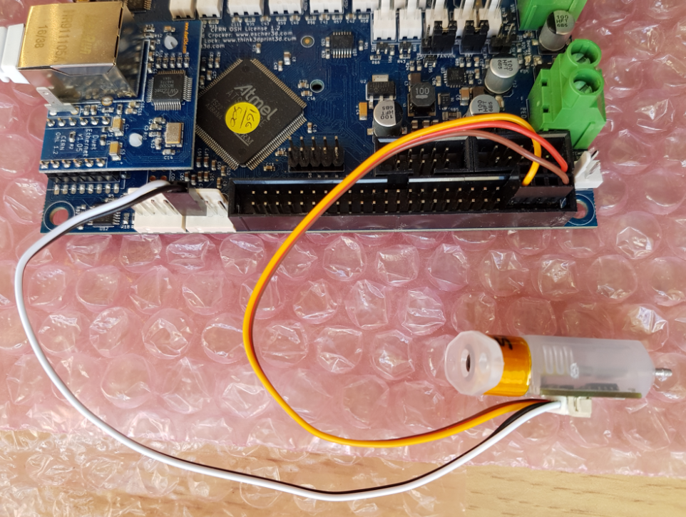
@oldironjunkie Please post a picture of your wiring on the Duet/Duex, and on the back of the BLTouch. Also post your firmware version by sending M115 and posting the response. It may also make it easier if you post your full config.g, and the deployprobe.g and retractprobe.g files.
The only instructions we recommend you read are the official ones; see https://docs.duet3d.com/User_manual/Connecting_hardware/Z_probe_connecting#bltouch
Under 'Wiring your BLTouch', click on the "Duet 2 WiFi/Ethernet with Duex 2, Duex 5 or EBoB" tab to show the Duex wiring and configuration.If the BLTouch is doing the self-test, then it is getting some voltage. It would be better just to wire it to the PWM1 header on the Duex, rather than the Z endstop connector, so it gets 5V; I'm not sure it works correctly on 3.3V (the Antclabs documentation says 5V on the red wire, assuming your BLTouch is genuine).
Also, if you have a Duex v0.9 or v0.9a board, check that you have a jumper on the "5V AUX JUMPER SELECT PINS" between the 5V AUX and 5V INT pins. Without this, the PWM connector doesn't get 5V.
The PWM connector supplies 5V and also has a connector for GND, so you can wire:
- the red (5V)
- brown and black (GND, wire one or both to the same pin, they are a shared ground on the BLTouch)
- orange PWM wire
Make sure you are not using the E2_heater output, as it shares the PWM pin with the PWM1 output on the Duex (E2_heater is shared with PWM1, E3_heater is shared with PWM2, etc). You need to use a free heater channel.
That leaves the white signal wire, which should go to zprobe.in. You should also use a pullup on the probe.in signal, ie:
M558 P9 C"^zprobe.in" H3 F100 T9000 R0.5. Generally, DWC should show the Z probe value as 0, and will change to 1000 (usually only for a fraction of a second, so often it doesn't register in DWC) when the probe is triggered. If you see 1000, check your wiring, as you are probably feeding 3.3V (or more) into the probe pin.Ian
Bed-slinger - Mini5+ WiFi/1LC | RRP Fisher v1 - D2 WiFi | Polargraph - D2 WiFi | TronXY X5S - 6HC/Roto | CNC router - 6HC | Tractus3D T1250 - D2 Eth
-
@droftarts
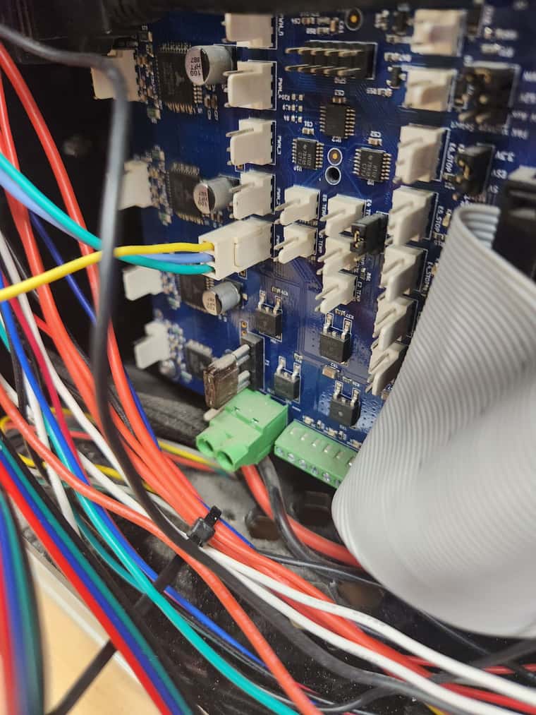
CONNECTED TO THE PWM1 HEADER:
GREEN WIRE CONNECTS TO THE BROWN WIRE ON THE BL TOUCH
BLUE WIRE CINNECTS TO THE ORANGE WIRE ON THE BL TOUCH
YELLOW WIRE CONNECTS TO THE YELLOW WIRE ON THE BL TOUCH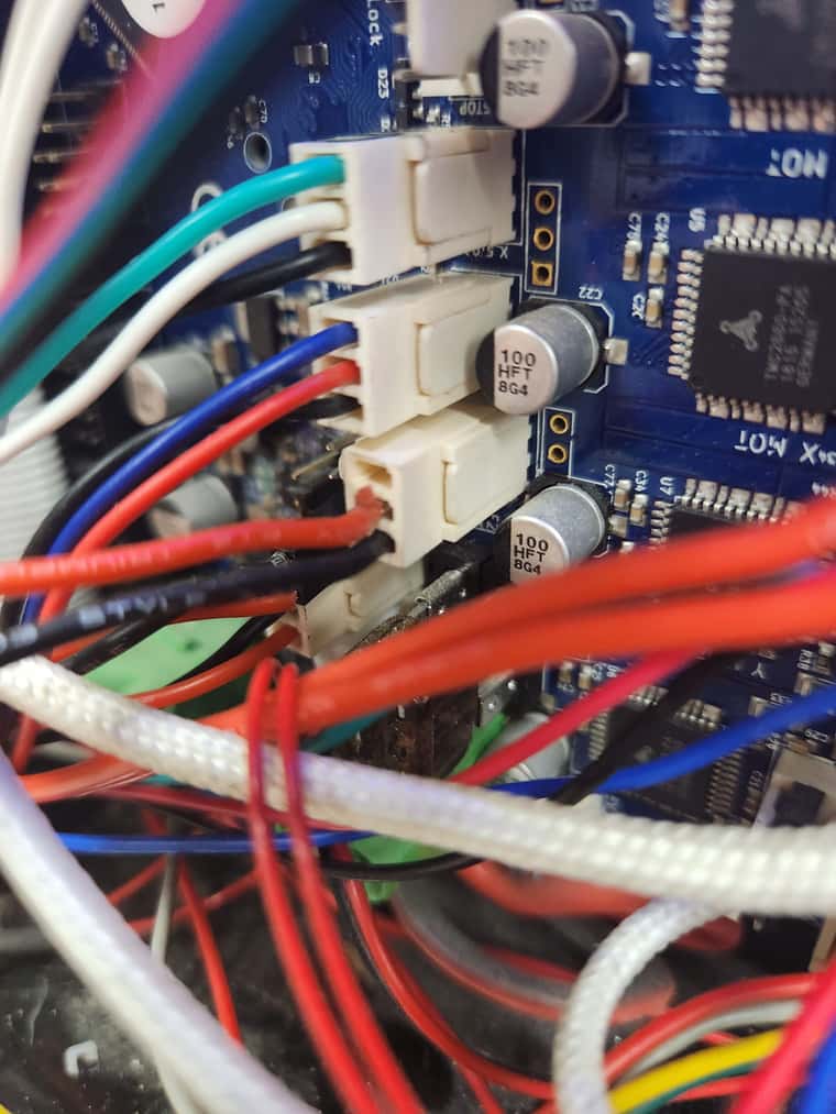
CONNECTED TO Z BROBE HEADER:
BLACK WIRE CONNECTS TOT THE BLACK WIRE ON THE BL TOUCH
RED WIRE CONNECTS TO THE WHITE WIRE ON THE BL TOUCH
THIRD POSITION IS BLANK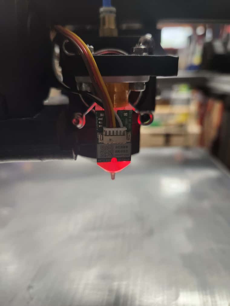
GENUINE BL TOUCH SMART VER.2.0
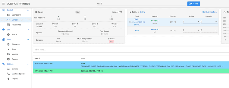
FIRMWARE VERSION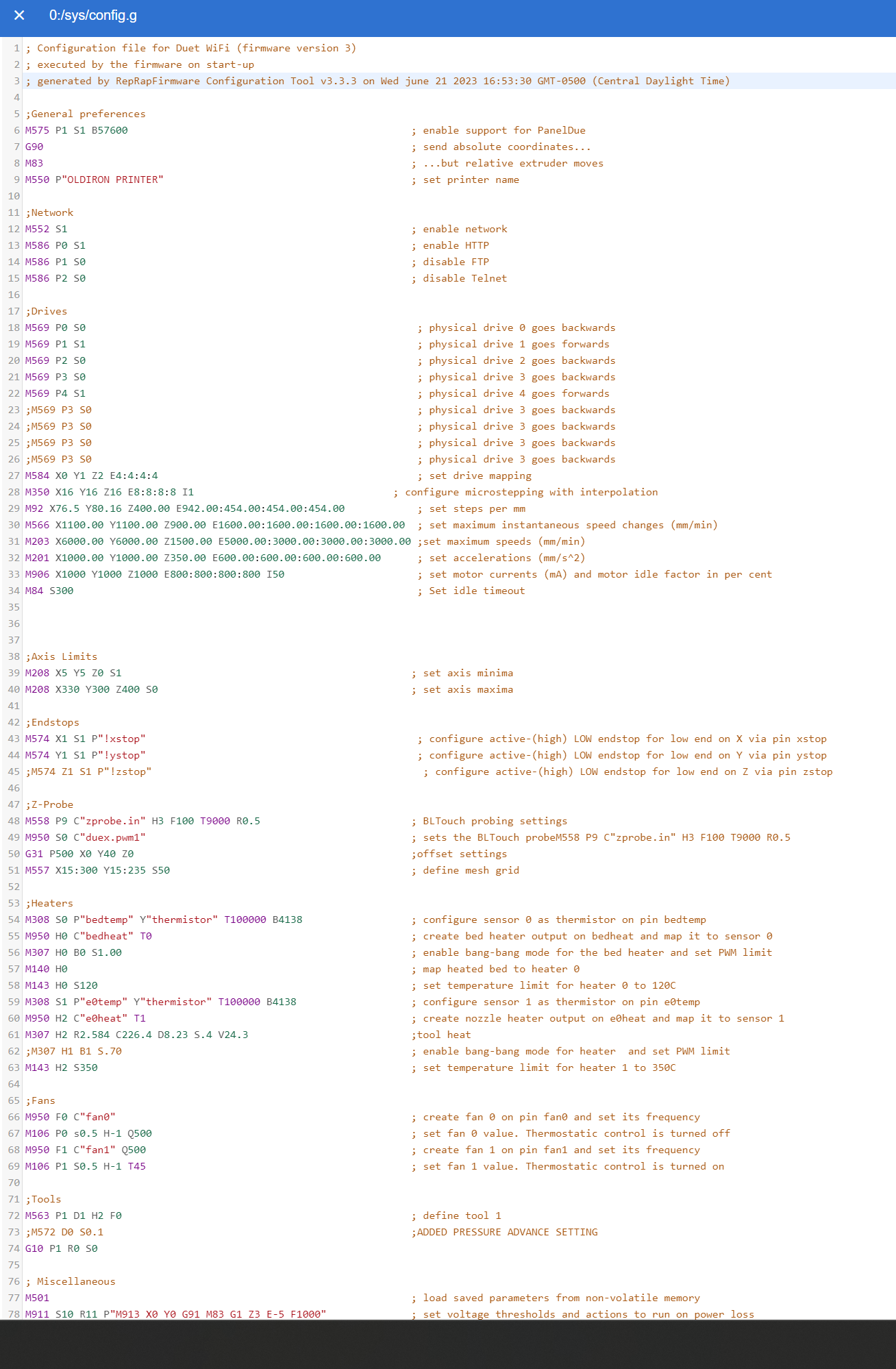
CONFIG .G FILE -
@oldironjunkie You can copy the text of your config.g (or any other file) and paste it into your reply here. Extra points if you put it between code tabs. Posting a picture of your config.g makes it much harder to quote parts that need to change.
Ian
Bed-slinger - Mini5+ WiFi/1LC | RRP Fisher v1 - D2 WiFi | Polargraph - D2 WiFi | TronXY X5S - 6HC/Roto | CNC router - 6HC | Tractus3D T1250 - D2 Eth
-
@droftarts I forgot to mention that the only things changed in the config file is that the extruder drive was remapped to #4 driver ( #3 driver is not working/shorted out with my new extruder which I replaced)
The Z probe has been commented out.
The tool heat was commented out and replaced by a PID setting for the tool. -
@oldironjunkie You have connected the BLTouch to the Z endstop, not the Z-probe header. See https://docs.duet3d.com/Duet3D_hardware/Duet_2_family/Duet_2_WiFi_Ethernet_Hardware_Overview#wiring-diagram
Ian
Bed-slinger - Mini5+ WiFi/1LC | RRP Fisher v1 - D2 WiFi | Polargraph - D2 WiFi | TronXY X5S - 6HC/Roto | CNC router - 6HC | Tractus3D T1250 - D2 Eth
-
; Configuration file for Duet WiFi (firmware version 3) ; executed by the firmware on start-up ; generated by RepRapFirmware Configuration Tool v3.3.3 on Wed Sep 29 2021 16:53:30 GMT-0500 (Central Daylight Time) ;General preferences M575 P1 S1 B57600 ; enable support for PanelDue G90 ; send absolute coordinates... M83 ; ...but relative extruder moves M550 P"OLDIRON PRINTER" ; set printer name ;Network M552 S1 ; enable network M586 P0 S1 ; enable HTTP M586 P1 S0 ; disable FTP M586 P2 S0 ; disable Telnet ;Drives M569 P0 S0 ; physical drive 0 goes backwards M569 P1 S1 ; physical drive 1 goes forwards M569 P2 S0 ; physical drive 2 goes backwards M569 P3 S0 ; physical drive 3 goes backwards M569 P4 S1 ; physical drive 4 goes forwards ;M569 P3 S0 ; physical drive 3 goes backwards ;M569 P3 S0 ; physical drive 3 goes backwards ;M569 P3 S0 ; physical drive 3 goes backwards ;M569 P3 S0 ; physical drive 3 goes backwards M584 X0 Y1 Z2 E4:4:4:4 ; set drive mapping M350 X16 Y16 Z16 E8:8:8:8 I1 ; configure microstepping with interpolation M92 X76.5 Y80.16 Z400.00 E942.00:454.00:454.00:454.00 ; set steps per mm M566 X1100.00 Y1100.00 Z900.00 E1600.00:1600.00:1600.00:1600.00 ; set maximum instantaneous speed changes (mm/min) M203 X6000.00 Y6000.00 Z1500.00 E5000.00:3000.00:3000.00:3000.00 ;set maximum speeds (mm/min) M201 X1000.00 Y1000.00 Z350.00 E600.00:600.00:600.00:600.00 ; set accelerations (mm/s^2) M906 X1000 Y1000 Z1000 E800:800:800:800 I50 ; set motor currents (mA) and motor idle factor in per cent M84 S300 ; Set idle timeout ;Axis Limits M208 X5 Y5 Z0 S1 ; set axis minima M208 X330 Y300 Z400 S0 ; set axis maxima ;Endstops M574 X1 S1 P"!xstop" ; configure active-(high) LOW endstop for low end on X via pin xstop M574 Y1 S1 P"!ystop" ; configure active-(high) LOW endstop for low end on Y via pin ystop ;M574 Z1 S1 P"!zstop" ; configure active-(high) LOW endstop for low end on Z via pin zstop ;Z-Probe M558 P9 C"zprobe.in" H3 F100 T9000 R0.5 ; BLTouch probing settings M950 S0 C"duex.pwm1" ; sets the BLTouch probeM558 P9 C"zprobe.in" H3 F100 T9000 R0.5 ; G31 P500 X0 Y40 Z0 ;offset settings M557 X15:300 Y15:235 S50 ; define mesh grid ;Heaters M308 S0 P"bedtemp" Y"thermistor" T100000 B4138 ; configure sensor 0 as thermistor on pin bedtemp M950 H0 C"bedheat" T0 ; create bed heater output on bedheat and map it to sensor 0 M307 H0 B0 S1.00 ; enable bang-bang mode for the bed heater and set PWM limit M140 H0 ; map heated bed to heater 0 M143 H0 S120 ; set temperature limit for heater 0 to 120C M308 S1 P"e0temp" Y"thermistor" T100000 B4138 ; configure sensor 1 as thermistor on pin e0temp M950 H2 C"e0heat" T1 ; create nozzle heater output on e0heat and map it to sensor 1 M307 H2 R2.584 C226.4 D8.23 S.4 V24.3 ;tool heat ;M307 H1 B1 S.70 ; enable bang-bang mode for heater and set PWM limit M143 H2 S350 ; set temperature limit for heater 1 to 350C ;Fans M950 F0 C"fan0" ; create fan 0 on pin fan0 and set its frequency M106 P0 s0.5 H-1 Q500 ; set fan 0 value. Thermostatic control is turned off M950 F1 C"fan1" Q500 ; create fan 1 on pin fan1 and set its frequency M106 P1 S0.5 H-1 T45 ; set fan 1 value. Thermostatic control is turned on ;Tools M563 P1 D1 H2 F0 ; define tool 1 ;M572 D0 S0.1 ;ADDED PRESSURE ADVANCE SETTING G10 P1 R0 S0 ; Miscellaneous M501 ; load saved parameters from non-volatile memory M911 S10 R11 P"M913 X0 Y0 G91 M83 G1 Z3 E-5 F1000" ; set voltage thresholds and actions to run on power loss T1 ; select first tool G10 P0 X0 Y0 Z0 ; set tool 0 axis offsets -
@droftarts Wi change as necessary later today. Have some appointments I need to make ths afternoon.
-
@oldironjunkie See where the white and black wires go here?
Ian
Bed-slinger - Mini5+ WiFi/1LC | RRP Fisher v1 - D2 WiFi | Polargraph - D2 WiFi | TronXY X5S - 6HC/Roto | CNC router - 6HC | Tractus3D T1250 - D2 Eth
-
@droftarts I have accomplished all the items. Rehooked up the power and ground to the Z-probe header. Rechecked all the wiring. Self test still peforms flawlessly. The static tect to check the probe failed. The probe will not deploy with either the M401 or the M280 P0 S10 commands. I rechecked the voltages all ok. Question I have is this. Do I need to do anything with the Z stop header. I currently have a z stop intsalled and hooked up (needed to print something asap).
;General preferences
M575 P1 S1 B57600                                               ; enable support for PanelDue
G90                                                             ; send absolute coordinates...
M83                                                             ; ...but relative extruder moves
M550 P"OLDIRON PRINTER"                                         ; set printer name

;Network
M552 S1                                                         ; enable network
M586 P0 S1                                                      ; enable HTTP
M586 P1 S0                                                      ; disable FTP
M586 P2 S0                                                      ; disable Telnet

;Drives
M569 P0 S0                                                       ; physical drive 0 goes backwards
M569 P1 S1                                                       ; physical drive 1 goes forwards
M569 P2 S0                                                       ; physical drive 2 goes backwards
M569 P3 S0                                                       ; physical drive 3 goes backwards
M569 P4 S1													     ; physical drive 4 goes forwards
;M569 P3 S0                                                      ; physical drive 3 goes backwards
;M569 P3 S0                                                      ; physical drive 3 goes backwards
;M569 P3 S0                                                      ; physical drive 3 goes backwards
;M569 P3 S0                                                      ; physical drive 3 goes backwards
M584 X0 Y1 Z2 E4:4:4:4                                           ; set drive mapping
M350 X16 Y16 Z16 E8:8:8:8 I1                                     ; configure microstepping with interpolation
M92 X79.68 Y79.44 Z400.00 E8440:454.00:454.00:454.00             ; set steps per mm
M566 X900.00 Y900.00 Z900.00 E1600.00:1600.00:1600.00:1600.00    ; set maximum instantaneous speed changes (mm/min)
M203 X4000.00 Y4000.00 Z1500.00 E4000.00:4000.00:4000.00:4000.00 ;set maximum speeds (mm/min)
M201 X1000.00 Y1000.00 Z350.00 E600.00:600.00:600.00:600.00      ; set accelerations (mm/s^2)
M906 X1000 Y1000 Z1000 E800:800:800:800 I50                      ; set motor currents (mA) and motor idle factor in per cent
M84 S300                                                         ; Set idle timeout


;Axis Limits
M208 X5 Y5 Z0 S1                                                ; set axis minima
M208 X330 Y300 Z400 S0                                          ; set axis maxima

;Endstops
M574 X1 S1 P"!xstop"                                             ; configure active-(high) LOW endstop for low end on X via pin xstop
M574 Y1 S1 P"!ystop"                                             ; configure active-(high) LOW endstop for low end on Y via pin ystop
M574 Z1 S1 P"!zstop"                                             ; configure active-(high) LOW endstop for low end on Z via pin zstop

;Z-Probe
M950 S0 C"duex.pwm1"                                            ; Duet 2 WiFi/Ethernet + DueX2/5
M558 P9 C"^zprobe.in" H5 F120 T6000 							; Duet 2 WiFi/Ethernet, DueX2/5
G31 X40 Y0 Z2.5 P25												;probe offsets, trigger height and trigger value
M557 X15:300 Y15:235 S30                                        ;define mesh grid

;Heaters
M308 S0 P"bedtemp" Y"thermistor" T100000 B4138                  ; configure sensor 0 as thermistor on pin bedtemp
M950 H0 C"bedheat" T0                                           ; create bed heater output on bedheat and map it to sensor 0
M307 H0 B0 S1.00                                                ; enable bang-bang mode for the bed heater and set PWM limit
M140 H0                                                         ; map heated bed to heater 0
M143 H0 S120                                                    ; set temperature limit for heater 0 to 120C
M308 S1 P"e0temp" Y"thermistor" T100000 B4138                   ; configure sensor 1 as thermistor on pin e0temp
M950 H2 C"e0heat" T1                                            ; create nozzle heater output on e0heat and map it to sensor 1
M307 H2 R2.584 C226.4 D8.23 S.5 V24.3							;tool heat
;M307 H1 B1 S.70                                                ; enable bang-bang mode for heater  and set PWM limit
M143 H2 S350                                                    ; set temperature limit for heater 1 to 350C

;Fans
M950 F0 C"fan0"                                                 ; create fan 0 on pin fan0 and set its frequency
M106 P0 S.75 H-1 Q500                                           ; set fan 0 value. Thermostatic control is turned off
M950 F1 C"fan1" Q500                                            ; create fan 1 on pin fan1 and set its frequency
M106 P1 S.75 H-1 Q500                                           ; set fan 1 value. Thermostatic control is turned on


;Tools
M563 P1 D1 H2 F0                           			 			; define tool 1
M572 D0 S0.06									                ;ADDED PRESSURE ADVANCE SETTING
G10 P1 R0 S0

; Miscellaneous
M501                                                            ; load saved parameters from non-volatile memory
M911 S10 R11 P"M913 X0 Y0 G91 M83 G1 Z3 E-5 F1000"              ; set voltage thresholds and actions to run on power loss
T1                                                              ; select first tool
G10 P0 X0 Y0 Z0                                           		; set tool 0 axis offsets
; deployprobe.g M280 P0 S10 ;code for deploying the Z probe; retractprobe.g M280 P0 S90 ;code for retracting the Z probeThye last 2 commands are in the system directory (is that where they belong)
Any other ideas?
-
@droftarts Sorry I sent the wrong config.g file hee is the correct one.
;General preferences M575 P1 S1 B57600 ; enable support for PanelDue G90 ; send absolute coordinates... M83 ; ...but relative extruder moves M550 P"OLDIRON PRINTER" ; set printer name ;Network M552 S1 ; enable network M586 P0 S1 ; enable HTTP M586 P1 S0 ; disable FTP M586 P2 S0 ; disable Telnet ;Drives M569 P0 S0 ; physical drive 0 goes backwards M569 P1 S1 ; physical drive 1 goes forwards M569 P2 S0 ; physical drive 2 goes backwards M569 P3 S0 ; physical drive 3 goes backwards M569 P4 S1 ; physical drive 4 goes forwards ;M569 P3 S0 ; physical drive 3 goes backwards ;M569 P3 S0 ; physical drive 3 goes backwards ;M569 P3 S0 ; physical drive 3 goes backwards ;M569 P3 S0 ; physical drive 3 goes backwards M584 X0 Y1 Z2 E4:4:4:4 ; set drive mapping M350 X16 Y16 Z16 E8:8:8:8 I1 ; configure microstepping with interpolation M92 X79.68 Y79.44 Z400.00 E8440:454.00:454.00:454.00 ; set steps per mm M566 X900.00 Y900.00 Z900.00 E1600.00:1600.00:1600.00:1600.00 ; set maximum instantaneous speed changes (mm/min) M203 X4000.00 Y4000.00 Z1500.00 E4000.00:4000.00:4000.00:4000.00 ;set maximum speeds (mm/min) M201 X1000.00 Y1000.00 Z350.00 E600.00:600.00:600.00:600.00 ; set accelerations (mm/s^2) M906 X1000 Y1000 Z1000 E800:800:800:800 I50 ; set motor currents (mA) and motor idle factor in per cent M84 S300 ; Set idle timeout ;Axis Limits M208 X5 Y5 Z0 S1 ; set axis minima M208 X330 Y300 Z400 S0 ; set axis maxima ;Endstops M574 X1 S1 P"!xstop" ; configure active-(high) LOW endstop for low end on X via pin xstop M574 Y1 S1 P"!ystop" ; configure active-(high) LOW endstop for low end on Y via pin ystop M574 Z1 S1 P"!zstop" ; configure active-(high) LOW endstop for low end on Z via pin zstop ;Z-Probe M950 S0 C"duex.pwm1" ; Duet 2 WiFi/Ethernet + DueX2/5 M558 P9 C"^zprobe.in" H3 F100 T9000 R0.5 ; Duet 2 WiFi/Ethernet, DueX2/5 G31 X40 Y0 Z2.5 P25 ;probe offsets, trigger height and trigger value M557 X15:300 Y15:235 S30 ;define mesh grid ;Heaters M308 S0 P"bedtemp" Y"thermistor" T100000 B4138 ; configure sensor 0 as thermistor on pin bedtemp M950 H0 C"bedheat" T0 ; create bed heater output on bedheat and map it to sensor 0 M307 H0 B0 S1.00 ; enable bang-bang mode for the bed heater and set PWM limit M140 H0 ; map heated bed to heater 0 M143 H0 S120 ; set temperature limit for heater 0 to 120C M308 S1 P"e0temp" Y"thermistor" T100000 B4138 ; configure sensor 1 as thermistor on pin e0temp M950 H2 C"e0heat" T1 ; create nozzle heater output on e0heat and map it to sensor 1 M307 H2 R2.584 C226.4 D8.23 S.5 V24.3 ;tool heat ;M307 H1 B1 S.70 ; enable bang-bang mode for heater and set PWM limit M143 H2 S350 ; set temperature limit for heater 1 to 350C ;Fans M950 F0 C"fan0" ; create fan 0 on pin fan0 and set its frequency M106 P0 S.75 H-1 Q500 ; set fan 0 value. Thermostatic control is turned off M950 F1 C"fan1" Q500 ; create fan 1 on pin fan1 and set its frequency M106 P1 S.75 H-1 Q500 ; set fan 1 value. Thermostatic control is turned on ;Tools M563 P1 D1 H2 F0 ; define tool 1 M572 D0 S0.06 ;ADDED PRESSURE ADVANCE SETTING G10 P1 R0 S0 ; Miscellaneous M501 ; load saved parameters from non-volatile memory M911 S10 R11 P"M913 X0 Y0 G91 M83 G1 Z3 E-5 F1000" ; set voltage thresholds and actions to run on power loss T1 ; select first tool G10 P0 X0 Y0 Z0 ; set tool 0 axis offsets -
@oldironjunkie did you do this?
Also, if you have a Duex v0.9 or v0.9a board, check that you have a jumper on the "5V AUX JUMPER SELECT PINS" between the 5V AUX and 5V INT pins. Without this, the PWM connector doesn't get 5V.
Ian
Bed-slinger - Mini5+ WiFi/1LC | RRP Fisher v1 - D2 WiFi | Polargraph - D2 WiFi | TronXY X5S - 6HC/Roto | CNC router - 6HC | Tractus3D T1250 - D2 Eth
-
@droftarts there is a jumper between pins marked "5V INT" and "5V AUX" . the header is between the endstop E2-E6 headers and the thermistor E2-E6 headers
-
@droftarts I also checked the voltage manuall with a meter and I have 4.96V dc
-
@oldironjunkie Can you post pictures of how it is wired now?
Can you sendM98 P"config.g"and post the response from the console?Edit: check the continuity of each of the wires, to make sure all of them are making a connection.
Ian
Bed-slinger - Mini5+ WiFi/1LC | RRP Fisher v1 - D2 WiFi | Polargraph - D2 WiFi | TronXY X5S - 6HC/Roto | CNC router - 6HC | Tractus3D T1250 - D2 Eth
-
This post is deleted! -
@droftarts Thanks for the response. I id find a bad connection in the tiny 5 pin factory connection on the BL touch. I fixed it by replacing the harnes with a known good one. Rechecked all and it is ok. The probe now expends and retracts with the M401 and M402 commands as it should. I did the calibration set up and I can home all axis. @ questions.How do I get to home the X and Y at the endstops in th upper right corner (where it is now) but I cannot get the z to home to the pin unless I run a G30 from the console. Also at the same time I would like to probe the z in the center of the bed (A150 and Y150) as this is where most of my prints start. Below are my homeall.g file and homez.g files. I only added the commands I need. Not sure what I need to add or comment out. Also once I get it al working correctly where do I enter the offset from the Bl touch to the nozzle. It is a consistent .59. Sorry about the questions but I am completely at a loss at this time.
; homeall.g
; called to home all axes
;
; generated by RepRapFirmware Configuration Tool v3.3.3 on Wed Sep 29 2021 16:53:30 GMT-0500 (Central Daylight Time)
G91                     ; relative positioning
G1 H2 Z5 F6000          ; lift Z relative to current position
G1 H1 X-302 Y-302 F6000 ; move quickly to X and Y axis endstops and stop there (first pass)
G1 H2 X5 Y5 F6000       ; go back a few mm
G1 H1 X-302 Y-302 F180  ; move slowly to X and Y axis endstops once more (second pass)
G30 S-1
; homez.g ; called to home the Z axis ; ; generated by RepRapFirmware Configuration Tool v3.3.3 on Wed Sep 29 2021 16:53:30 GMT-0500 (Central Daylight Time) M98 P"homeall.g" ; Call the home X & Y macro to home those axes first M98 P"deployprobe.g" ; Called to extend the BL-Touch probe pin to allow probing to take place G30 S-1 ; Home the Z axis by probing the bed M98 P"retractprobe.g" -
@oldironjunkie 2 questions
- why are your macros called
extendpin.gand notdeployprobe.g? Likewise forretractpin.gandretractprobe.g... - Why are you not using
M401/M402butM98 P"deployprobe.g"andM98 P"retractprobe.g"?
<>RatRig V-Minion Fly Super5Pro RRF<> V-Core 3.1 IDEX k*****r <> RatRig V-Minion SKR 2 Marlin<>
- why are your macros called
-
This post is deleted! -
@oliof I was using those names beacause that is what I was sent by a friend of mine. It has changes since. I will post the final files once it is done, working and tested. I am in the process of doing that now but unfortunatly life just gets in the way.