Duet3D Logo Duet3D
    • Tags
    • Documentation
    • Order
    • Register
    • Login

    Problems with input shaping

    Scheduled Pinned Locked Moved
    Tuning and tweaking
    5
    47
    2.7k
    Loading More Posts
    • Oldest to Newest
    • Newest to Oldest
    • Most Votes
    Reply
    • Reply as topic
    Log in to reply
    This topic has been deleted. Only users with topic management privileges can see it.
    • Leeundefined
      Lee @droftarts
      last edited by Lee

      @droftarts Here are pictures of the cabel it selfe i have connected the shielding oh the wire to ground (underneath The shrink tubing)
      continuity is good aswell

      1 Reply Last reply Reply Quote 0
      • Leeundefined
        Lee @tas
        last edited by Lee

        @tas https://forum.duet3d.com/topic/31411/lis3dsh-orientation-on-a-delta-printer/6
        I have checked I16 seems to be right for me.

        I have installed the the version you suggested i am was able to finish the data collection.

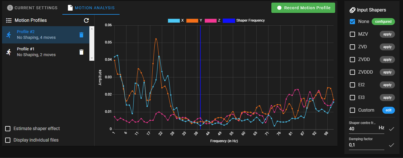
        here are the results: (using M566 X150.00 Y150.00 Z150.00)
        d4bc100c-4c85-45f4-8d7a-689c7318823e-image.png

        tasundefined droftartsundefined 2 Replies Last reply Reply Quote 0
        • tasundefined
          tas @Lee
          last edited by

          @Lee It's good the data collection is working properly now so your cable is likely ok. Your frequency is still around 20Hz though. I think you need a delta expert to help and that is not definitely not me. Perhaps @dc42 could take a look for you.

          Leeundefined 1 Reply Last reply Reply Quote 0
          • Leeundefined
            Lee @tas
            last edited by

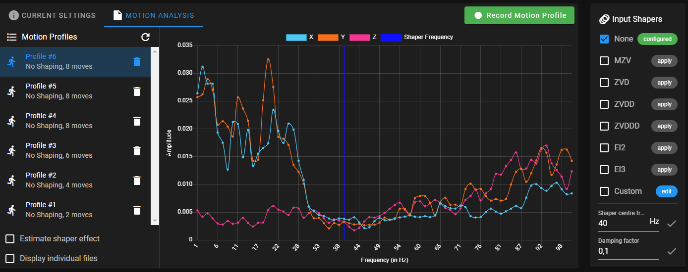
            @tas I have run some more recordings and they all look almost Identical.

            e1acd950-715c-4ee5-8812-e9c7988756bb-image.png

            1 Reply Last reply Reply Quote 0
            • droftartsundefined
              droftarts administrators @Lee
              last edited by

              @Lee Sorry, I wasn't aware of a bug in DWC that was causing this, and that it was fixed. Thanks @tas for spotting this! Now onto the next problem... have you run a print since lowering jerk, to see if it makes any difference?

              Ian

              Bed-slinger - Mini5+ WiFi/1LC | RRP Fisher v1 - D2 WiFi | Polargraph - D2 WiFi | TronXY X5S - 6HC/Roto | CNC router - 6HC | Tractus3D T1250 - D2 Eth

              Leeundefined 1 Reply Last reply Reply Quote 0
              • Leeundefined
                Lee @droftarts
                last edited by Lee

                @droftarts I have not run a test print jett but i will start on now

                Leeundefined 1 Reply Last reply Reply Quote 0
                • Leeundefined
                  Lee @Lee
                  last edited by

                  This was printed ad 60 mm/S and M593 P"ZVDDD" F19,5 S0
                  81529bd5-8c0d-485d-bd56-1ca7cf4daa17-IMG_2436.jpeg 5f313dd8-72f0-413f-a2b5-d340713ab0cc-IMG_2435.jpeg

                  tasundefined gloomyandyundefined 3 Replies Last reply Reply Quote 0
                  • tasundefined
                    tas @Lee
                    last edited by

                    @Lee Keep in mind I have no delta experience but the pattern of thin vertical lines looks like Very Fine Artifacts to me. That will not be addressed by input shaping.

                    The echoes of the scallop pattern are what you want to examine. There do appear to be some first layer issues you may want to deal with first.

                    1 Reply Last reply Reply Quote 0
                    • tasundefined
                      tas @Lee
                      last edited by

                      @Lee I finally got my Ender 5 Plus back up and running today with new E3D 0.9 degree stepper motors (trying to get rid of my VFAs!). I will have to do a full recalibration so I will do some Input Shaping tests and see if I can come up with something of help to you.

                      1 Reply Last reply Reply Quote 0
                      • tasundefined
                        tas
                        last edited by

                        @Lee I did some tests.

                        I now have the E3D 0.9 degree motors for X and Y. This has changed a lot for me so I have to do a full recalibration of the printer. For these tests I used my original values though and enabled only input shaping using my new center frequency of 39 Hz. So Acceleration of 1400 and Jerk max of 900. M593 P"EI3" F39.0 S0.0.

                        I used PrusaSlicer 2.6.0 with the following custom g-code in Printer Settings>After Layer Change G-Code:

                        ;Try Input Shapers
                        {if layer_z >= 0.2}M593 P"none"{endif}
                        {if layer_z >= 5.0}M593 P"mzv" F39 S0.0{endif}
                        {if layer_z >= 10.0}M593 P"zvd" F39 S0.0{endif}
                        {if layer_z >= 15.0}M593 P"zvdd" F39 S0.0{endif}
                        {if layer_z >= 20.0}M593 P"zvddd" F39 S0.0{endif}
                        {if layer_z >= 25.0}M593 P"ei2" F39 S0.0{endif}
                        {if layer_z >= 30.0}M593 P"ei3" F39 S0.0{endif}

                        Using the Klipper Ringing_Tower.stl as you did the above code chooses another Input Shaper at each new scallop.

                        So first sample, Acceleration 1400, Jerk 900, speed 50mm/s, no PA. I apologize in advance for my photography. Not great.

                        Jerk 900, acc 1400 spd 50mms-2.JPG

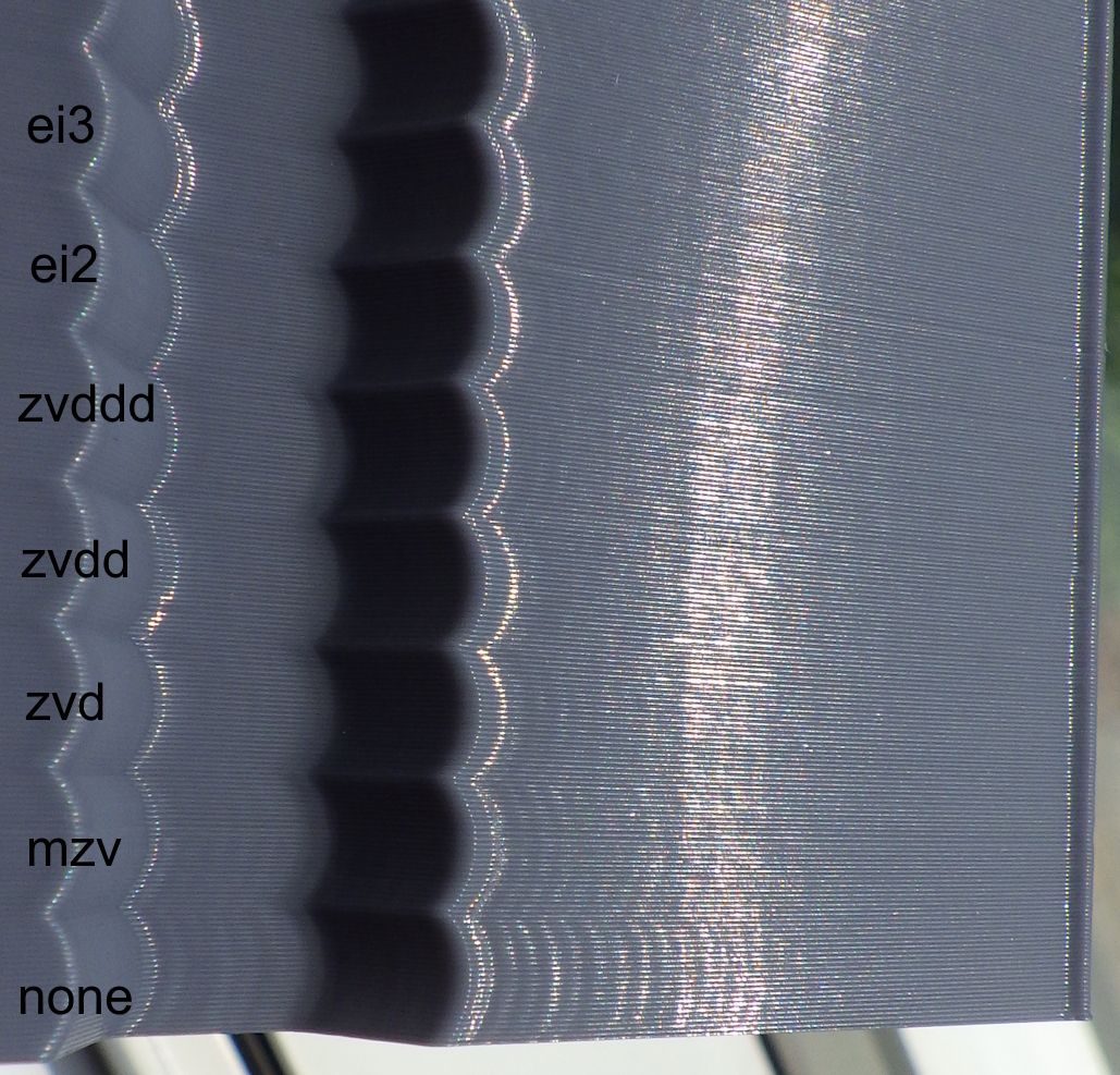
                        There is a slight difference at each corner for the different input shapers. This does not show up in my photos. For some shapers the start side of the corner looks better, for others the end side. For 'none' there is prolonged ringing and varying (but much less ringing) for the input shapers.

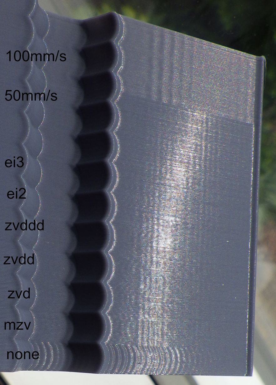
                        For the second sample I changed Jerk to 100 from 900. On the last three scallops at the top I doubled the speed to 100mm/s. A shallow wave appeared at that speed. Jerk gives worse ringing at 100 with no input shaper because the 1400 acceleration worked best with 900 jerk (and my old motors). However the lower jerk looks much better with input shaping. There is definitely less ringing.

                        Jerk 100, acc 1400 spd 50mms and 100mms.JPG .

                        You should definitely see a difference with input shaping enabled.

                        Leeundefined 1 Reply Last reply Reply Quote 0
                        • gloomyandyundefined
                          gloomyandy @Lee
                          last edited by

                          @Lee As others have said the resonance frequency you are targeting (19.5Hz in the above is very low) and my understanding is that input shaping does not work well below approx 25Hz. This is a comment from the Klipper documentation:

                          Another consideration is that if a resonance frequency is too low (below 20-25 Hz), it might be a good idea to increase the printer stiffness or reduce the moving mass. Otherwise, acceleration and printing speed may be limited due too much smoothing now instead of ringing.
                          
                          Leeundefined 1 Reply Last reply Reply Quote 0
                          • Leeundefined
                            Lee @gloomyandy
                            last edited by

                            @gloomyandy but what frequency should i use than? No matter what I do the results are almost identical every time

                            jay_s_ukundefined gloomyandyundefined 2 Replies Last reply Reply Quote 0
                            • Leeundefined
                              Lee @tas
                              last edited by

                              @tas I also have the e3d 0.9 degree motor i will try printing with the g code modifiers you used

                              1 Reply Last reply Reply Quote 0
                              • jay_s_ukundefined
                                jay_s_uk @Lee
                                last edited by

                                @Lee can you show how you are mounting the accelerometer?

                                Owns various duet boards and is the main wiki maintainer for the Teamgloomy LPC/STM32 port of RRF. Assume I'm running whatever the latest beta/stable build is

                                Leeundefined 1 Reply Last reply Reply Quote 0
                                • Leeundefined
                                  Lee @jay_s_uk
                                  last edited by

                                  @jay_s_uk There us a picture above it is mounted at the back of the tool head

                                  jay_s_ukundefined 1 Reply Last reply Reply Quote 0
                                  • jay_s_ukundefined
                                    jay_s_uk @Lee
                                    last edited by

                                    @Lee you may need to improve the mounting to make it more fixed

                                    Owns various duet boards and is the main wiki maintainer for the Teamgloomy LPC/STM32 port of RRF. Assume I'm running whatever the latest beta/stable build is

                                    Leeundefined 1 Reply Last reply Reply Quote 0
                                    • Leeundefined
                                      Lee @jay_s_uk
                                      last edited by

                                      @jay_s_uk I will try tighteing the screw that holding the accelerometer.

                                      jay_s_ukundefined 1 Reply Last reply Reply Quote 0
                                      • jay_s_ukundefined
                                        jay_s_uk @Lee
                                        last edited by

                                        @Lee you probably need more than just 1 screw

                                        Owns various duet boards and is the main wiki maintainer for the Teamgloomy LPC/STM32 port of RRF. Assume I'm running whatever the latest beta/stable build is

                                        Leeundefined 1 Reply Last reply Reply Quote 0
                                        • Leeundefined
                                          Lee @jay_s_uk
                                          last edited by

                                          @jay_s_uk ok than i will design a new holder

                                          1 Reply Last reply Reply Quote 0
                                          • gloomyandyundefined
                                            gloomyandy @Lee
                                            last edited by

                                            @Lee Looking at the test print you did I'm not actually seeing much ringing on it at all (you may be able to see more than we can in a photo). If you can see ringing on the print I'd ignore the accelerometer and just use the manual way of estimating the frequency by measuring the peaks of the ringing, see: https://www.klipper3d.org/Resonance_Compensation.html

                                            Leeundefined 2 Replies Last reply Reply Quote 0
                                            • First post
                                              Last post
                                            Unless otherwise noted, all forum content is licensed under CC-BY-SA