• Tags
  • Documentation
  • Order
  • Register
  • Login
Duet3D Logo Duet3D
  • Tags
  • Documentation
  • Order
  • Register
  • Login

Scanning Z probe support in RRF 3.5

Scheduled Pinned Locked Moved
Beta Firmware
23
128
10.0k
Loading More Posts
  • Oldest to Newest
  • Newest to Oldest
  • Most Votes
Reply
  • Reply as topic
Log in to reply
This topic has been deleted. Only users with topic management privileges can see it.
  • undefined
    samlogan87 @dc42
    last edited by 27 Jun 2023, 18:33

    @dc42 is this something that you think you can connect into existing tool boards going forward, or will we need to buy a new tool board

    Custom Core-XY

    undefined 1 Reply Last reply 29 Jun 2023, 07:55 Reply Quote 0
    • undefined
      dc42 administrators @samlogan87
      last edited by 29 Jun 2023, 07:55

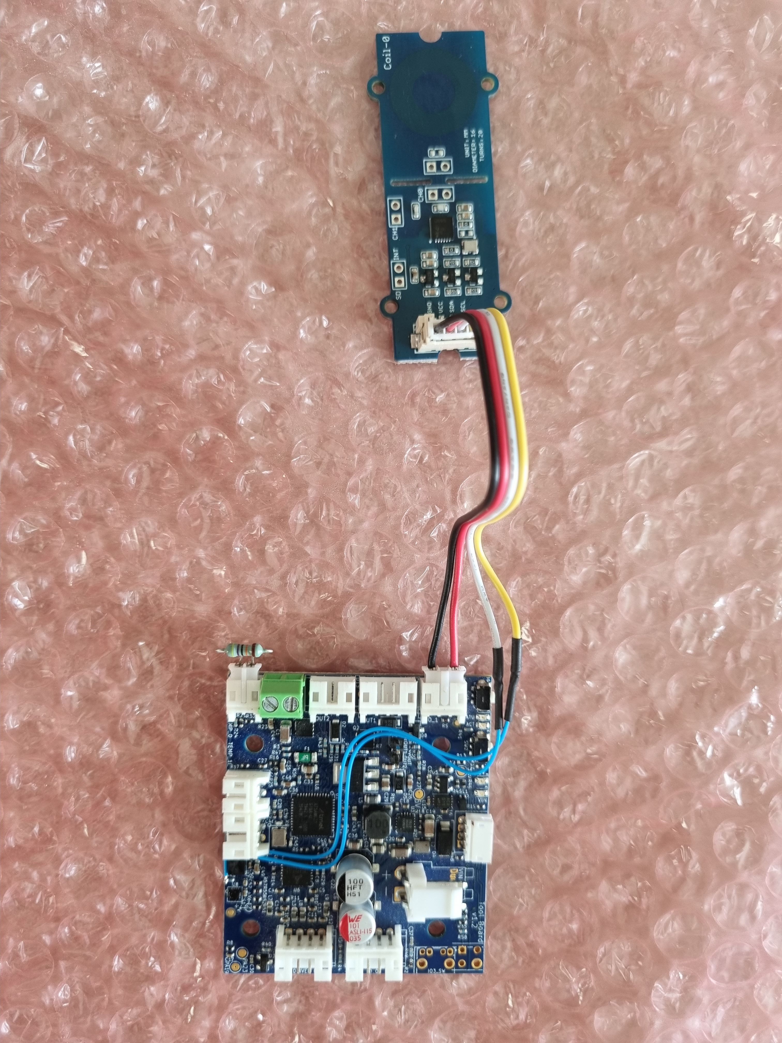
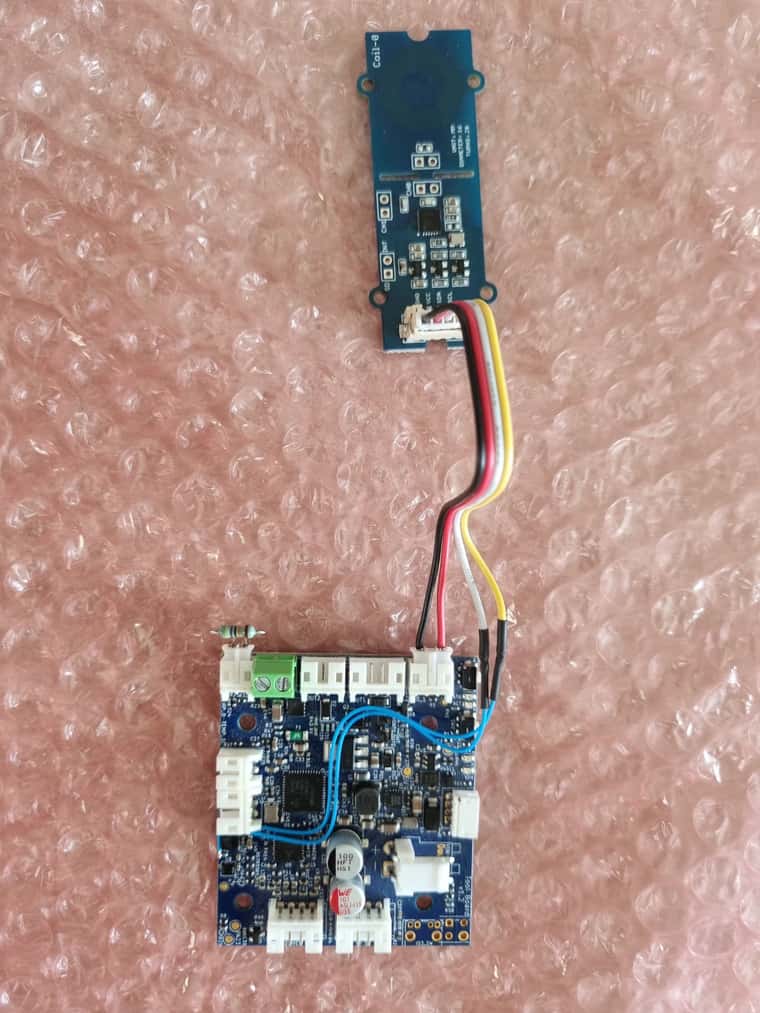
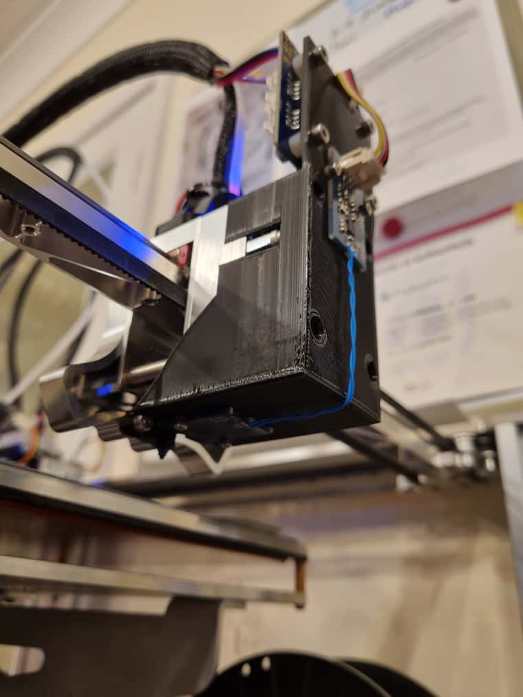
      @samlogan87 it can be connected to existing version 1.1 and later tool boards if you can use a soldering iron with a very fine tip. Here's how I connected mine.
      2023-06-17 14.29.40.jpg
      2023-06-17 14.29.23.jpg

      Duet WiFi hardware designer and firmware engineer
      Please do not ask me for Duet support via PM or email, use the forum
      http://www.escher3d.com, https://miscsolutions.wordpress.com

      undefined undefined 3 Replies Last reply 29 Jun 2023, 08:16 Reply Quote 0
      • undefined
        samlogan87 @dc42
        last edited by 29 Jun 2023, 08:16

        @dc42 Jeepers, these sausage fingers will struggle with that. Might have to ask a mate. It is hard to see where the upper connection point is from that photo

        Custom Core-XY

        undefined 1 Reply Last reply 30 Jun 2023, 07:52 Reply Quote 2
        • undefined
          CNCModeller @dc42
          last edited by 29 Jun 2023, 15:21

          @dc42 do you have a similar connection guide for a Sammy board?

          Polar Duet3 Mini + 1HCL
          https://youtube.com/playlist?list=PLWjZVEdMv1BY82izahK45qKh-hp3NFkix
          Wanhao D4S: Duet2
          https://forum.duet3d.com/post/296755
          K40 Laser, Duet2
          https://forum.duet3d.com/post/312082
          Wanhao D5S
          https://www.youtube.com/CNCModellerUK

          undefined 1 Reply Last reply 30 Jun 2023, 07:39 Reply Quote 0
          • undefined
            dc42 administrators @CNCModeller
            last edited by 30 Jun 2023, 07:39

            @CNCModeller when using our standard firmware build for the SammyC21, you would connect the SDA pin of the LDC1612 to PA22 and the SCL pin to PA23.

            Duet WiFi hardware designer and firmware engineer
            Please do not ask me for Duet support via PM or email, use the forum
            http://www.escher3d.com, https://miscsolutions.wordpress.com

            undefined undefined 2 Replies Last reply 30 Jun 2023, 10:09 Reply Quote 0
            • undefined
              JoergS5 @samlogan87
              last edited by JoergS5 7 Mar 2023, 00:18 30 Jun 2023, 07:52

              @samlogan87 said in Scanning Z probe support in RRF 3.5:

              hard to see where the upper connection point i

              I would say it is the left side of R55 R53. I would 3D a little housing and use two pogo pins to make the connection, so there would be no need to solder. I've ordered the Grove board and will make experiments also.

              1 Reply Last reply Reply Quote 0
              • undefined
                samlogan87 @dc42
                last edited by 30 Jun 2023, 08:11

                @dc42 I have a 1.1 revision board which has the SWD Out plug where you have soldered onto. I am not going to do it now as I will wait for you to finish testing but where would I hook it up to?

                Custom Core-XY

                undefined 1 Reply Last reply 30 Jun 2023, 11:37 Reply Quote 0
                • undefined
                  CNCModeller @dc42
                  last edited by 30 Jun 2023, 10:09

                  @dc42 said in Scanning Z probe support in RRF 3.5:

                  @CNCModeller when using our standard firmware build for the SammyC21, you would connect the SDA pin of the LDC1612 to PA22 and the SCL pin to PA23.

                  Ok thanks, just ordered an LDC1612, should be here in a week or so. Something else to add to the list of upgrades for my printer.

                  I'm assuming that this would work for scanning copper clad PCBs or metallic stock on a CNC milling machine to determine a surface deviation map or the lowest height on a stock top surface for Z work offsets?

                  Cheers
                  Barry M

                  Polar Duet3 Mini + 1HCL
                  https://youtube.com/playlist?list=PLWjZVEdMv1BY82izahK45qKh-hp3NFkix
                  Wanhao D4S: Duet2
                  https://forum.duet3d.com/post/296755
                  K40 Laser, Duet2
                  https://forum.duet3d.com/post/312082
                  Wanhao D5S
                  https://www.youtube.com/CNCModellerUK

                  1 Reply Last reply Reply Quote 0
                  • undefined
                    dc42 administrators @samlogan87
                    last edited by 30 Jun 2023, 11:37

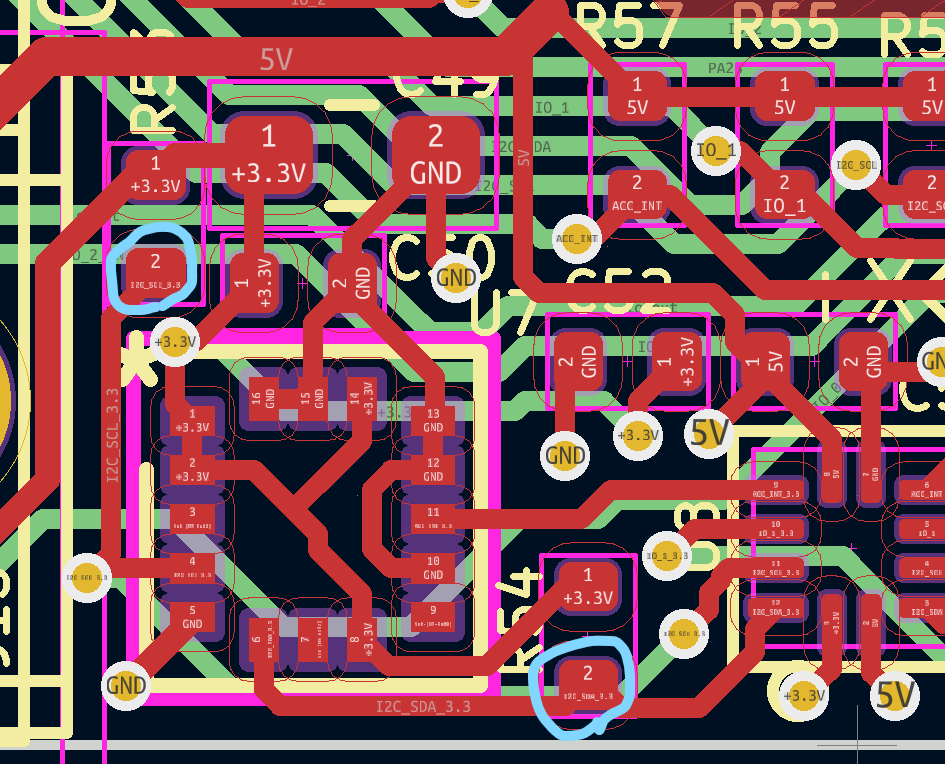
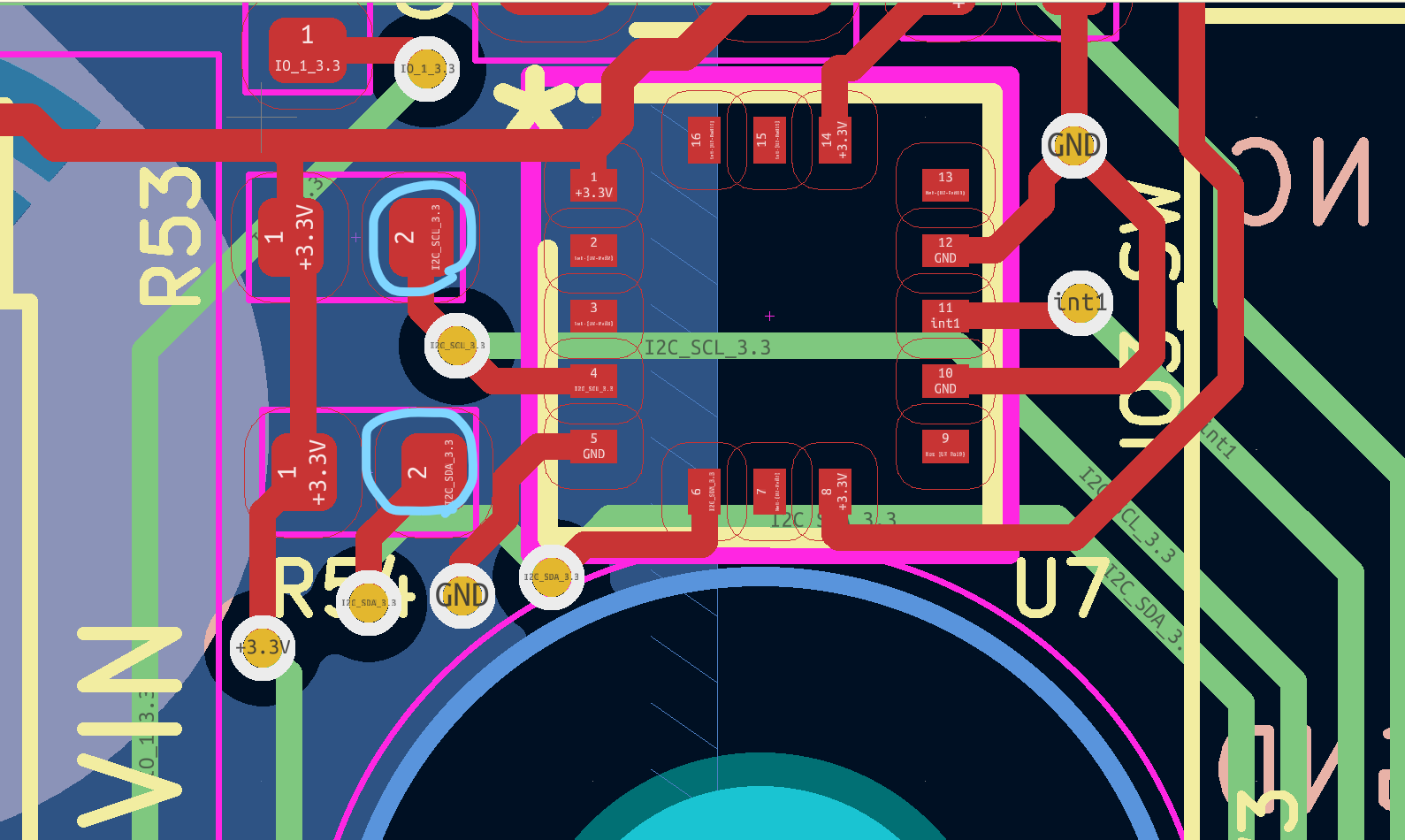
                    @samlogan87 here are the connections (circled in blue) for a revision 1.2 tool board, which is what I used. I'll take a look at where they would be made on a revision 1.1 board.

                    a40ea966-c25e-4112-be50-88bdf4869cbb-image.png

                    Duet WiFi hardware designer and firmware engineer
                    Please do not ask me for Duet support via PM or email, use the forum
                    http://www.escher3d.com, https://miscsolutions.wordpress.com

                    undefined 1 Reply Last reply 30 Jun 2023, 11:41 Reply Quote 0
                    • undefined
                      dc42 administrators @dc42
                      last edited by 30 Jun 2023, 11:41

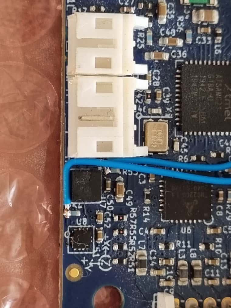
                      ...and here are the corresponding connections on a version 1.1 tool board, again to resistors next to the accelerometer chip.

                      dc78c840-5ecd-4b79-a21c-1d130f0c0a1f-image.png

                      Duet WiFi hardware designer and firmware engineer
                      Please do not ask me for Duet support via PM or email, use the forum
                      http://www.escher3d.com, https://miscsolutions.wordpress.com

                      1 Reply Last reply Reply Quote 1
                      • undefined
                        lparnell34 @dc42
                        last edited by 30 Jun 2023, 16:22

                        @dc42 could you share your M558 and M558.1 Gcode for the scanning probe?

                        undefined 1 Reply Last reply 30 Jun 2023, 16:54 Reply Quote 0
                        • undefined
                          dc42 administrators @lparnell34
                          last edited by dc42 30 Jun 2023, 16:54

                          @lparnell34 currently I use the standard tool changer Z probe microswitch for Z homing because it doesn't have the temperature sensitivity that inductive Z probes have. I have the scanning probe configured as an additional probe for use with G29. Here's an extract from config.g:

                          ; Z probe
                          M558 K0 P8 C"io3.in" H3 F1000:600 I0 T30000 ; Set Z probe type to switch, the axes for which it is used and the dive height + speeds
                          G31 P200 X0 Y0 Z0 ; Set Z probe trigger value, offset and trigger height
                          ;M557 X-140:140 Y-80:80 S40 ; Define mesh grid
                          ; Scanning Z probe
                          M558 K1 P11 C"24.i2c.ldc1612" F25000 T30000
                          G31 K1 Z3 Y-17
                          M557 X-140:140 Y-90:80 S12 ; Define mesh grid

                          I changed my mesh.g file to recognise the K1 parameter (i.e. use the second Z probe) and do the M558.1 calibration at the start to avoid possible temperature sensitivity issues:

                          T-1
                          M208 S0 Y100
                          if exists(param.K) & param.K=1
                          G1 X0 Y0 F30000
                          M558.1 K1 S2
                          G29 S0 K{exists(param.K) ? param.K : 0}
                          G1 X0 Y0 F24000
                          M208 S0 Y49
                          G1 Y-150

                          Then I send G29 K1 to do the scan. The M208 commands are included because on the tool changer, the Y axis limit depends on which tool is selected.

                          Duet WiFi hardware designer and firmware engineer
                          Please do not ask me for Duet support via PM or email, use the forum
                          http://www.escher3d.com, https://miscsolutions.wordpress.com

                          undefined undefined 2 Replies Last reply 30 Jun 2023, 17:26 Reply Quote 0
                          • undefined
                            lparnell34 @dc42
                            last edited by 30 Jun 2023, 17:26

                            @dc42 thanks. I'm using the tool changer too. Do you just have the coil pcb mounted to the bottom of the toolhead cover?

                            undefined 1 Reply Last reply 30 Jun 2023, 20:39 Reply Quote 0
                            • undefined
                              dc42 administrators @lparnell34
                              last edited by 30 Jun 2023, 20:39

                              @lparnell34 initially yes, however that gave a large Y offset between the coil and the Z probe switch; so I extended the cover towards the switch.

                              2023-06-30 21.37.16.jpg

                              Duet WiFi hardware designer and firmware engineer
                              Please do not ask me for Duet support via PM or email, use the forum
                              http://www.escher3d.com, https://miscsolutions.wordpress.com

                              undefined 1 Reply Last reply 2 Jul 2023, 21:35 Reply Quote 0
                              • undefined
                                dc42 administrators @dc42
                                last edited by 2 Jul 2023, 21:35

                                Here's a blog entry with more details about this scanning probe: https://www.duet3d.com/blog/scanning-z-probe-for-reprapfirmware-and-Duet.

                                Duet WiFi hardware designer and firmware engineer
                                Please do not ask me for Duet support via PM or email, use the forum
                                http://www.escher3d.com, https://miscsolutions.wordpress.com

                                undefined 1 Reply Last reply 3 Jul 2023, 07:12 Reply Quote 4
                                • undefined
                                  JoergS5
                                  last edited by 3 Jul 2023, 00:29

                                  This post is deleted!
                                  1 Reply Last reply Reply Quote 0
                                  • undefined
                                    samlogan87 @dc42
                                    last edited by 3 Jul 2023, 07:12

                                    @dc42 do you guys think you will release a new version of the tool board where you put the i2c bus to a plug? Had another look tonight and there is no way I would be able to solder that 🤣

                                    Custom Core-XY

                                    undefined 1 Reply Last reply 3 Jul 2023, 07:27 Reply Quote 0
                                    • undefined
                                      dc42 administrators @samlogan87
                                      last edited by 3 Jul 2023, 07:27

                                      @JoergS5 I'm not sure why you deleted your post, however I had the same idea yesterday!

                                      Duet WiFi hardware designer and firmware engineer
                                      Please do not ask me for Duet support via PM or email, use the forum
                                      http://www.escher3d.com, https://miscsolutions.wordpress.com

                                      undefined 1 Reply Last reply 3 Jul 2023, 08:00 Reply Quote 0
                                      • undefined
                                        JoergS5 @dc42
                                        last edited by JoergS5 7 Mar 2023, 08:57 3 Jul 2023, 08:00

                                        @dc42 I deleted it because I doubt whether the BL Touch is necessary in the future *). But to repeat my idea:

                                        is it possible to bore a hole into the middle of the Grove coil and assemble it together with the BL Touch so the pin of the BL Touch goes through the coil hole. Then both have the same XY offset.

                                        *) I thought about using a gauge block at a bed edge as Z0 reference.
                                        Gauge blocks of class 0 have a precision of 0.1 micrometers. This could even be used with the LDC1612 measuring the angle of a rotated bed => 5 axis AC calibration, by measuring multiple points on the gauge block.

                                        The next idea was, if I don't use the BLTouch, I could use the bored coil to assemble it around the nozzle, so it has true X0Y0 position. The PCB needs to have enough distance to the heated nozzle... => the aluminium heatblock will disturb measurement

                                        undefined 1 Reply Last reply 3 Jul 2023, 08:24 Reply Quote 0
                                        • undefined
                                          dc42 administrators @JoergS5
                                          last edited by dc42 3 Jul 2023, 08:24

                                          @JoergS5 my feeling at the moment is that because of the sensitivity of inductive sensors to temperature, and to allow a wider choice of bed surfaces including interchangeable beds, it's better to use a conventional touch probe or nozzle contact probe to establish Z=0 and perhaps to do bed tramming too. Then the scanning probe can be calibrated immediately before scanning, and its temperature sensitivity won't matter.

                                          As you can see from the pictures at https://coolcomponents.co.uk/products/grove-2-channel-inductive-sensor-ldc1612 there is a blank area in the centre of the coil, so drilling a hole there would be possible.

                                          We're designing a solution based on the LDC1612 at present and although we will be using a smaller sense coil than the Grove one, it's likely that we will include a hole in the centre and design a printable adapter to attach it to a BLTouch.

                                          Duet WiFi hardware designer and firmware engineer
                                          Please do not ask me for Duet support via PM or email, use the forum
                                          http://www.escher3d.com, https://miscsolutions.wordpress.com

                                          undefined undefined undefined 3 Replies Last reply 3 Jul 2023, 08:36 Reply Quote 0
                                          37 out of 128
                                          • First post
                                            37/128
                                            Last post
                                          Unless otherwise noted, all forum content is licensed under CC-BY-SA