Hollow shaft extruder
-
@nikscha Do you think there's any way you can reduce the diameter of the large gear? My first impression was that it would be a bit top heavy, though a lighter motor would help with that. @o_lampe 's point about it being a long way from the drive gear to the hot end, particularly for flexible filaments, could also be problematic.
What is your view on the Archimedes screw extruder?
Ian
Bed-slinger - Mini5+ WiFi/1LC | RRP Fisher v1 - D2 WiFi | Polargraph - D2 WiFi | TronXY X5S - 6HC/Roto | CNC router - 6HC | Tractus3D T1250 - D2 Eth
-
Sorry for highjacking this post by the way, I made a separate one here:
https://forum.duet3d.com/topic/32876/ingenuity-extruder-for-smart-effector -
@nikscha said in Hollow shaft extruder:
Sorry for highjacking this post by the way
No worries, after all your extruder is a hollow shaft extruder, and that's what this thread is about!
Ian
-
@droftarts said in Hollow shaft extruder:
@nikscha Do you think there's any way you can reduce the diameter of the large gear? My first impression was that it would be a bit top heavy, though a lighter motor would help with that. @o_lampe 's point about it being a long way from the drive gear to the hot end, particularly for flexible filaments, could also be problematic.
What is your view on the Archimedes screw extruder?
Ian
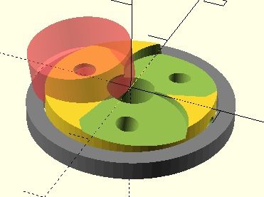
Well the diameter of the "wheel" depends on multiple factors, like hypoid offset, gear ratio and number of teeth.
The hypoid offset is limited by the diameter of the drive wheel, which is the bondtech LGX in my case. gear ratio is aimed at 1:7, and tooth size is limited by the material properties.
I made all my prototypes from resin gears (Sirayatech white mecha), which were quite brittle, but I've since moved to gears made from IGUS SLS plastics. They're much stronger and more durable, and with them it might be possible to have a smaller wheel and/or a higher reduction ratio.While testing I found that the "top heaviness" isn't that much of a problem, I'll post my input shaping results later for proof
")
.
.
.About the Archimedes screw extruder:
Very neat! And so light! I am jealous!
But there's no way of tensioning the filament, and loading/unloading can only be done electronically.
A harder filament will also provide more resistance to deformation which might stall the extruder. A softer filament might slip. There's also only one "teeth" engaging with the filament, so it might slip easier, especially considering that there's no way of tensioning it.
Abrasive filament will also dull the knife edge.Edit:
A quick calculation shows that at 15degree pitch one revolution of the screw will advance the filament by about 1.5mm (tan15 * 1.75 *pi), the archimedes extruder has (360/1.8)= 200 steps per revolution, so about 133.33 steps per mm, which is not that much.Edit2: judging from this: https://youtu.be/YTADdWiFQnI?t=238 my math is wrong, and the archimedes extruder needs about two revolutions to advance the filament by 1.75mm, which implies 1.14 revolutions for 1mm. This is equal to 228 steps/mm
-
 undefined nikscha referenced this topic
-
@nikscha Thanks for joining the conversation.
I've made some small gears with ABS-like resin and also Anycubics tough resin.
Especially the latter is promising for testing gears. Could you achieve the same ratio with a smaller module? Your hypoid wheel looks like it can lift a car...but there is not much torque to deal with. -
@o_lampe
I don't think resin gears are the way forward. You want something abrasion resistant because hypoid bevel gears slightly rub against each other, it's not a pure rolling motion like spur gears for example.
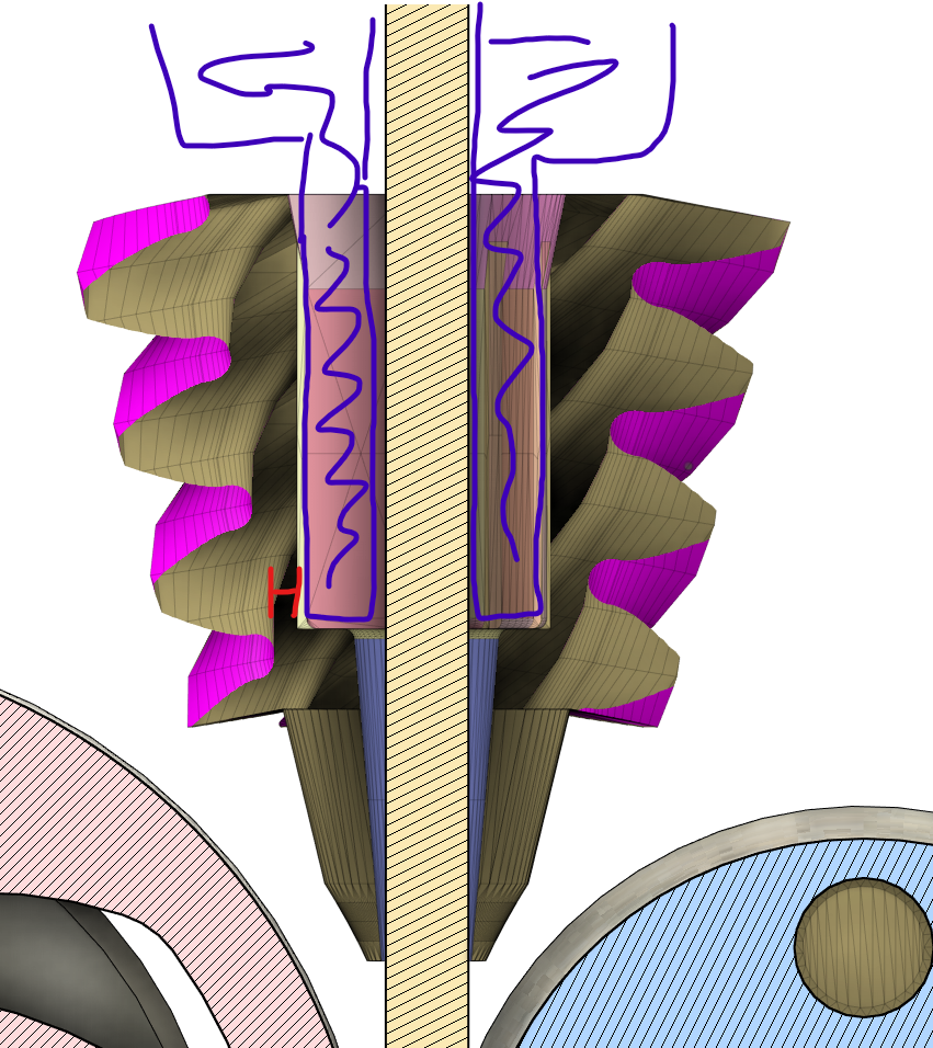
Instead I'm using SLS printed gears (IGUS).One BIG problem that needs solving is the stepper getting hot. Usually this isn't a problem, but with a hollow shaft extruder the filament going through the shaft will get hot. Pla especially will soften quickly. Resin printed pinions that sit on the shaft will soften as well.
I had to run my old stepper at 600mA, while it's rated at 800, just to prevent overheating. I remedy this by counterboring the shaft from the top, and inserting a thin-walled ptfe tube for insulation.
The new stepper that has the ptfe tube and Igus gears can run hotter (obviously), but I haven't tested it enough yet.If you have a delta printer and a smart effector and want to help me test, please hit me up, I'll gladly sent you a gear pair and custom stepper motor.
Stay in school
-
You definitely could archive the same ratio with a smaller module.
Don't overestimate the hypoid gears tho, the ratio is only about 1:7, and the stepper is a nema 14, so not much torque here either.I should also state again that the diameter of the bigger gear is a function of hypoid shift. Hypoid shift is among other determined by the diameter of the drive wheel, in my case an LGX hardened drive wheel by bondtech. You could use a smaller one, maybe something that's used in the orbiter which is using 12mm diameter drive wheels instead of the LGX 18mm, which makes the hypoid shift 6mm instead of 9mm.
But this now means that the pinion is so small that you can't have it sit on a stepper motor shaft, it's diameter is now only 4mm instead of the 5.7mm I get with the LGX gears. This means that the red section will be too thin:
-
Interesting concept.
I'll be interested to see if the resonant frequencies common in hypoid gears have an effect on extrusion. -
@OwenD Could you elaborate? I haven't heard of those resonant frequencies
-
@nikscha said in Hollow shaft extruder:
@OwenD Could you elaborate? I haven't heard of those resonant frequencies
My experience with regards to printing has only been with the Zesty nimble.
If you search you should find plenty of examples of the artifacts.
The V2 version is supposed to have fixed this, but I'd given up by then.
Hence my interest to see if this implementation of similar gears will present with the same issues.The older of us would be well familiar with these frequencies on car differentials.
There is plenty of research on how these frequencies occur, but the math is well over my head. -
I printed @MIHAIDESIGNS extruder test piece and it looks very smooth.
Does that answer your question?
-
@nikscha said in Hollow shaft extruder:
I printed @MIHAIDESIGNS extruder test piece and it looks very smooth.
Does that answer your question?I don't see the same patterns, but there does seem to be some irregular extrusion in places.
It probably looks worse in the photo than in person and is way less than the issue I had.
Not trying to hose down the idea, just interested from a mechanics point of view. -
You're right, they're not perfect. But close

I used to use the Flex3Drive and the Ingenuity extruder is quite a bit more consistent.MirageC made some interesting conclusions in this video, which I tried to consider in my design.
The alignment of the gears is constrained by the LGX drive gear and a roller bearing, and the idler is basically flat, so there shouldn't be any lateral forces on the filament:
-
@nikscha said in Hollow shaft extruder:
I don't think resin gears are the way forward.
It's perfect for testing and the ABS-like resin withstands 200°C+ , way more than the stepper temp will raise.
It's also a good starting point if you want to cast a silicone mould and reproduce it in bigger quantities.
Although the abrasion of an hypoid gear is an issue without lube or grease. Did you try that? -
@o_lampe i started with siraya tech white mecha resin which is an abrasion resistant resin, but it was too brittle. I mixxed in 10% siraya tech tenacious to make it tougher. That worked, but under higher temperatures the resin would still soften. For testing I just ran the printer a bit slower and reduced the current, and I'm very happy with the geometry now.
For people who want to build their own, a resin printed gear is probably totally fine.
I also really like the idea of using a mold, thanks!
Yes I usually lubricate the gears which makes them run about 20% smoother. I have also tried running them dry for a while and I haven't seen any significant wear on the gears yet.
-
I wonder why the VDE100 (archimedes) base has to be so exact? In the video, he had to grind the flanged bearing to a certain diameter to make it work with the base.
If the shafts of the bearings would tilt slightly outwards, we could add some springs and have them autoadjust (self tightening) to the right diameter.
A ring-lever which would push the bearings against the springs, would release the filament if it needs to be removed.
Inserting new filament would be just...inserting.
Similar concept we know from the PTFE tube fittings... -
@o_lampe That's a nice idea. You would need a very stiff but small spring. A disc spring seems ideal.
The ring lever is also smart, I'm imagining an inverse "ramp" on the bottom of it which pushes the lever up and down, depending on the position of the lever. The bearings then press/ride against the smooth top of the lever.
This could be used to set a maximum tension as well. -
@nikscha The original VDE100 files are somewhere on thingiverse, including an (*) FreeCad parametric file.
I really suck with modifying any CAD when it's not my design. Do you volunteer to make a version of our idea?- The wavy washers might work, but they don't have much room to compress.
- The ring lever should hold a plain washer because the bearings will rotate on it.
- The spring force must be big enough to have working retraction without slip.
Couldn't find it there but on reprap-forum
Carrier#3.FCStd -
@o_lampe I never used freeCad but maybe I can make a copy of the design in Fusion. Will take a while though.
-
I translated the FreeCad data to OpenScad and added a variable "tilt"
Here's a 5° tilt
And the OpenScad file.
carrier_tilted.scadReduced carrier diameter and sort-off lever added, just for clarification