Hollow shaft extruder
-
@nikscha @tombrazier
comparing your current/torque demands should start with comparing the stepper settings like microstepping and steps/mm.
The big LDX drivegear feeds almost 60mm filament/turn that requires a lot of torque.
From rq3's posts I've learned that the archimedes screw needs pretty high steps/mm setting. He even didn't use microstepping.
That resulted in a low max. extrusion speed (on Marlin @12V ).
His design went through several changes and Tom's carrier seems different again.
I'd be interested about the status quo regarding the latest numbers, Tom? -
@nikscha I have not tested but I think that my VDE extruder could not lift 4kg - or if it did it would experience some much widening of the grooves that the helical thread pitch on the filament would reduce to pretty much zero. However, 4kg equates to a nozzle pressure of something like 16MPa, which I think is probably a lot higher than ever would be needed for extrusion. With fluid dynamics, there is a point where flow stops being laminar and flow rate pretty much stops increasing with increased pressure. And with feeding filament through an extruder, there is a point where it is feeding too fast to fully melt, which also places a fairly abrupt upper limit on flow rate, regardless of pressure. Volcano and CHT type nozzles help but even they have their limits. I would be interested to know at what pressure the cut-off typically is, but naively I suspect it is below 16MPa. Stefan from CNC kitchen has done a lot of work exploring these limits but I can't remember whether he has put a load cell on his extruder to measure extrusion force at the limits of flow.
High flow rate is a bit of a weakness with the VDE because of the groove widening thing I mentioned above. I have vague ideas of experimenting with more flanged bearings and different edge shapes. But in reality it is only sub 20 minute speed benchies that challenge my VDE for flow rate so it's not my highest priority.
@o_lampe I don't think microstepping is relevant in the speed/torque calculations, but it is a factor when configuring the firmware. I have a 20° cant angle on my bearings and this results in a lower steps/mm than rq3 gets with his 15° cant angle. I am presently using use microstepping = 2 with my VDE and getting about 275 steps/mm (1.8° motor).
-
@tombrazier this is really valuable information, this means I could probably get away with a much lighter stepper. I'll do some testing with lower currents to see how little torque is actually required.
About the groove widening: why not stack a second ring with 3 more bearings on top? If you get the spacing right, the second ring won't even have to cut it's own groove, and the load is shared between the two.
-
@nikscha said in Hollow shaft extruder:
About the groove widening: why not stack a second ring with 3 more bearings on top? If you get the spacing right, the second ring won't even have to cut it's own groove, and the load is shared between the two.
Mainly because I have not needed to. I don't usually print fast enough for it to be a problem. But it is one idea I have thought about. Another that strikes me is that the edge I grind on the bearing has an included angle of 45° and rq3 uses 60°, but I suspect the ridges on a bondtech gear have more like 90°. I would be interested to know whether a wider included angle results in better grip. And another is to use symmetric edges as rq3 does, which I now have the means to grind whereas I did not previously.
-
@nikscha said in Hollow shaft extruder:
I'll do some testing with lower currents to see how little torque is actually required.
The trick will be to figure out at what speed your extruder's flow rate hits the wall. Then tune current so that the E stepper does not start losing steps before that point.
-
@tombrazier fair I could do that, but isn't that highly dependent on nozzle-dia, meltzone length, filament etc? I would get a number that works for me but maybe not for others, right?
Maybe I could test how much weight the LGX mini and the Orbiter (I have both) can lift and compare that to the Ingenuity. Then I have a rough estimate of what is "expected", and I can adjust the torque according
-
@tombrazier I'd think that a bigger included angle actually makes grip worse. My train of thought is that Bondtech can get away with 90° because more than 1 tooth is engaged in the filament, and they choose 90 degrees because it holds up better against abrasive filament.
It makes sense that you don't need the second ring with the speeds you're going at. But I'm surprised that you don't print faster with such a lightweight extruder. That seems to be the biggest advantage to me. What other reasons are there to use your extruder instead of the Orbiter for example? You mentioned something about ease of disassembly earlier I think?
-
@nikscha said in Hollow shaft extruder:
What other reasons are there to use your extruder instead of the Orbiter for example? You mentioned something about ease of disassembly earlier I think?How about the print artifacts attributed to dual drive gear extruders? I suspect the screw-type extruder doesn't suffer the same problem.
-
@mrehorstdmd yeah I don't see how that would be possible. There's way less moving parts and no gears at all.
@tombrazier did you print mihaidesigns extruder test piece? I'd be curious whether any patterns show up there. -
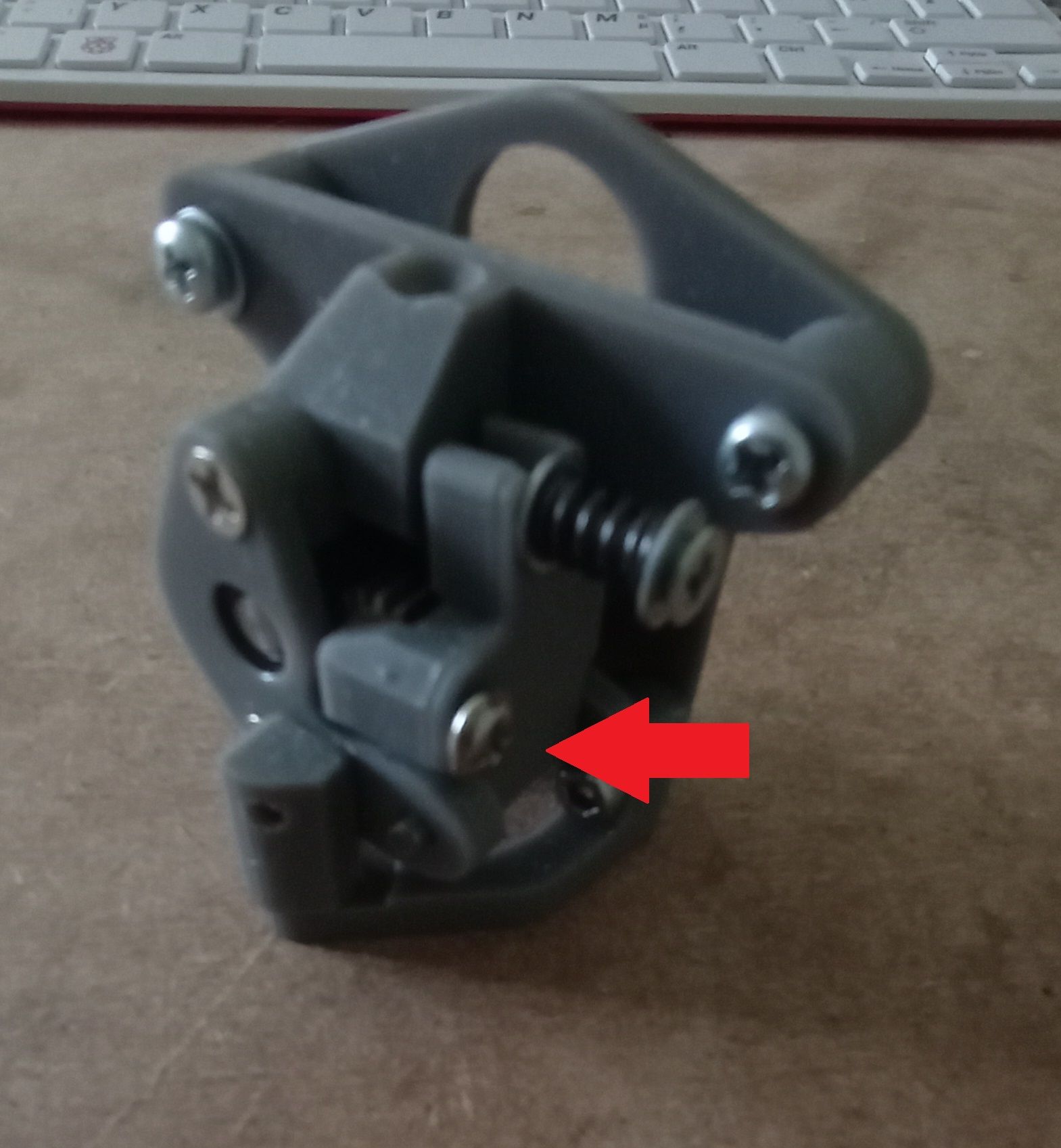
I found a simple way to deal with the BMG gear issue, would be interesting to print the extruder test.
I added a screw to adjust the gear-mesh no matter how the tension spring is set.
Do you have a link?First I thought, I had to become patron, but he offers the test file for free on his HP
-
@o_lampe Interesting, do you have a picture of it in CAD? I'm not familiar with the sherpa, so it's hard to tell what I'm looking at

Thanks also for the link for the extruder test piece.
-
@nikscha said in Hollow shaft extruder:
I'd think that a bigger included angle actually makes grip worse. My train of thought is that Bondtech can get away with 90° because more than 1 tooth is engaged in the filament, and they choose 90 degrees because it holds up better against abrasive filament.
That was my expectation too - mainly informed by how grip works on ice skates. The closer to vertical the side of the blade is, the more grip there is. But the thread widening effect acts like a plough wheel. It's not grip that is the problem but rather that a furrow is being ploughed through the plastic. You can actually see this and it really does look like ploughed earth with a little ridge piled up parallel to the thread. I am now wondering whether different plough wheel profiles would have different ploughing effects. I notice plough wheels tend to be thin. So if I don't actually want to plough, what if I used a more wedged shaped wheel?
I'm surprised that you don't print faster with such a lightweight extruder. That seems to be the biggest advantage to me. What other reasons are there to use your extruder instead of the Orbiter for example? You mentioned something about ease of disassembly earlier I think?
I tend to prefer a maximum 0.15mm layer height and often print at 0.1mm and sometimes at 0.05mm. This needs fast X and Y movement but does not need high extrusion rates.
Ease of disassembly is also a feature I value.
The killer features for me were the steps/mm ratio and the simplicity. I started with a cloning a Prusa extruder which drives a pair of bondtech gears with no gearing and with a significant sideways force applied to the end of the stepper shaft, which adds a lot of friction. My recycled E stepper often just could not produce enough torque to drive this configuration. Then I played with a printed split ring orbital gear assembly which was wonderful when it worked but sometimes would start spitting out bits of gear tooth mid-print. In comparison the VDE-100 was extremely light, needed very little current so there were no heat problems and just works.
And, as @mrehorstdmd suggests, the VDE-100 eliminates the artifacts related to the bondtech gears and the step size of the E stepper.
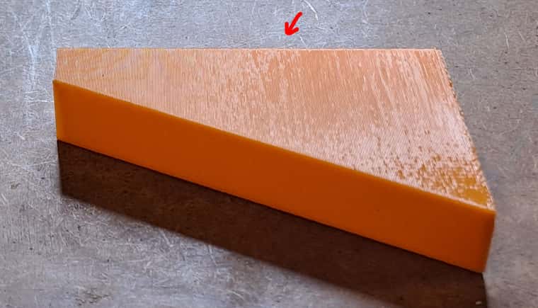
did you print mihaidesigns extruder test piece? I'd be curious whether any patterns show up there
It's printing now.
-
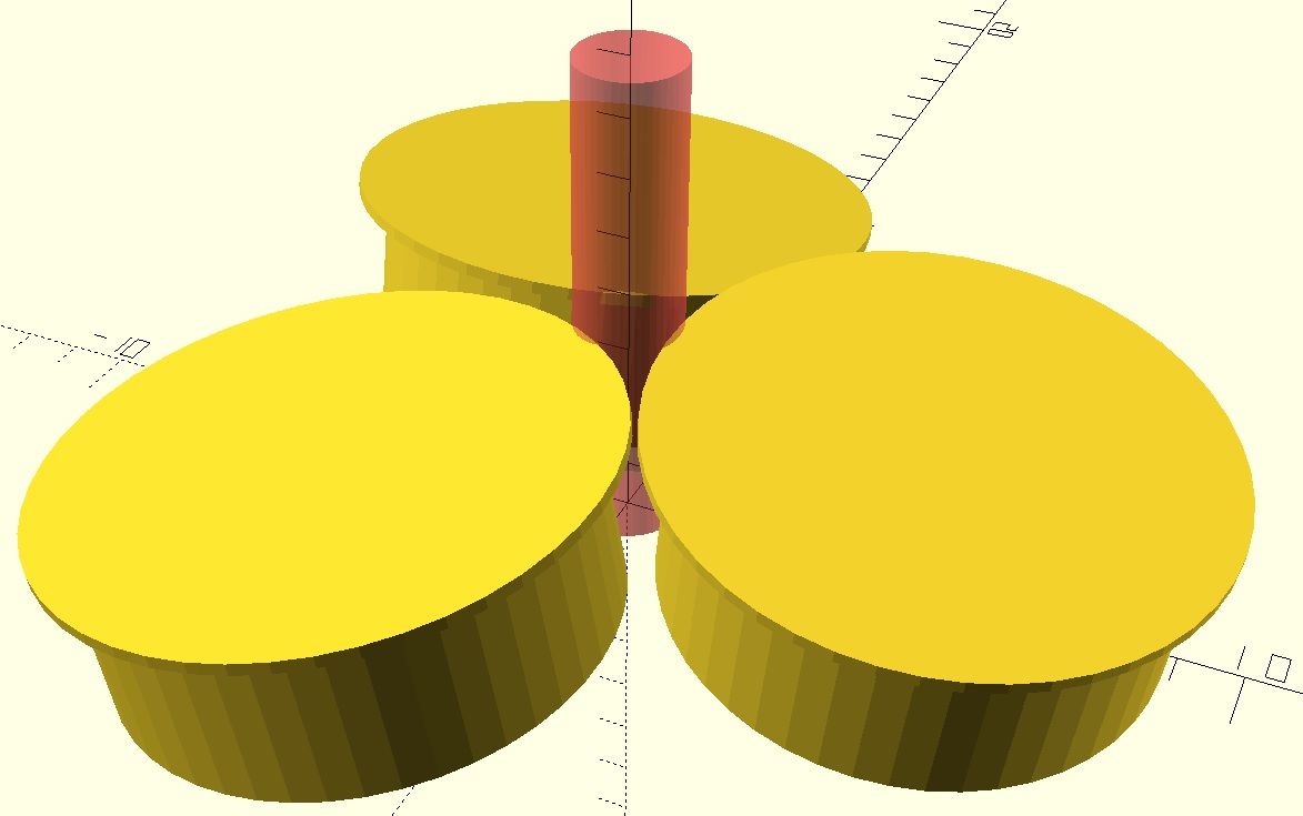
I made my first tilted VDE-100 carrier yesterday and tried to put some 10mm bearings on. Surprisingly they don't really cut it.
I tried several different setups, with or without washer underneath, 1,2 or 3 flanged bearings with flange up or down.My impression is, that it would work better with 8mm bearings, so I wrote another sketch to draw the bearings instead of the carrier.
Now I can see much clearer, how deep the flange would cut into the filament at a given offset and tilt-angle.
As a sidenote: the idea to push the bearings up with a ring lever will need extreme force, but one step at a time.
-
@o_lampe Yes, 10mm is too large. The bearings interfere with each other. I am now using MR85ZZ flanged bearings and a MF95ZZ pressure bearing. Even the MF95ZZ is a bit big and I have shaved the corners down a little to prevent interference.
And while I'm talking about bearings, ABEC rated bearings are a really good idea. Rq3 uses ABEC-5 and I have been using ABEC-3.
Your carrier appears to have all three bearings cutting the filament at the same height. This will create three grooves very close together and experience shows that that tends to just grind up the filament. I arrange my two knife-edged bearings so they run in the same groove.
Also note that the axis of rotation of each bearing needs to be positioned so that it comes to its closest point to the axis of the filament at the exact height where the knife edge cuts the filament.
-
@nikscha said in Hollow shaft extruder:
did you print mihaidesigns extruder test piece? I'd be curious whether any patterns show up there.
Here's a picture.

There is a very slight pattern but I found it really difficult to photograph. I have indicated with an arrow where you can see it in the photo.
-
@tombrazier said in Hollow shaft extruder:
Your carrier appears to have all three bearings cutting the filament at the same height. This will create three grooves very close together and experience shows that that tends to just grind up the filament
I agree, there is a downside with this arrangement, but each bearing has two opponent bearings and the filament has no way to move or flex.
I'm under the impression that the flanged bearing idea is not the best solution.
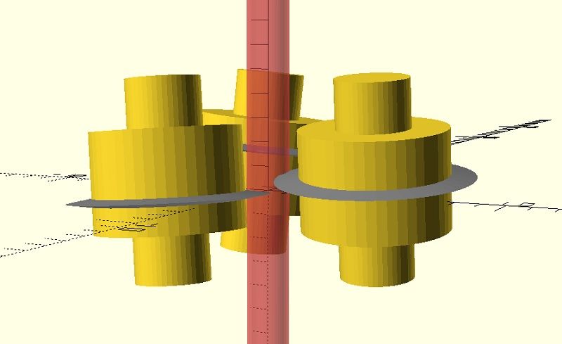
Maybe it's better to have three rotating shafts with blades at different heights and the ends of the shafts run in bearings.
These shafts could easily be CNC'd on a lathe and would cost next to nothing (thinking big) -
@o_lampe rq3 tried lots of those kinds of variations, including diamond dust glued to the bearings. Flanged bearings won handily. The problem with stacked blades is that there is only one point along the axis of the bearing/shaft that is the correct point for interfacing with the filament. It's the point I mentioned above where the axis of the bearing/shaft is closest to the axis of the filament. I would have to stop and think now to remember why that was so important, but I remember it was important.
[Edit: But do experiment. I experimented a lot as well and repeated a lot of rq3's findings. But there's always scope for finding something we've missed.]
-
@tombrazier
I quickly sketched something that looks like it could work. The blades are each 0.5mm different in height. That should be correct, when they are 120° apart and the advance is 1.5mm? Somehow it looks wrong, but it's just a matter of adapting the formula.
-
@o_lampe I see I misunderstood you. I thought you meant multiple blades per shaft.
The extruder you show with three blades is pretty much what I have been using for the last year, except I only have two blades and the third bearing is just a plain one that acts as am idler for the two blades. And, yes, the vertical spacing would be something like 0.5mm each for a 1.5mm thread pitch. For me this was really easy to implement using flanged bearings once I worked out an easy way of grinding the bearings. But shafts with blades as you suggest would work just as well and I agree it's more a matter of what is easier to manufacture.
-
@tombrazier said in Hollow shaft extruder:
That was my expectation too - mainly informed by how grip works on ice skates. The closer to vertical the side of the blade is, the more grip there is. But the thread widening effect acts like a plough wheel. It's not grip that is the problem but rather that a furrow is being ploughed through the plastic. You can actually see this and it really does look like ploughed earth with a little ridge piled up parallel to the thread. I am now wondering whether different plough wheel profiles would have different ploughing effects. I notice plough wheels tend to be thin. So if I don't actually want to plough, what if I used a more wedged shaped wheel?
I see. Do you have a macro shot of the filament after it has been extruded? Would also be interesting to see the difference between filament that has been extruded with a "load" applied vs without. Probably the pitch will change then? And/or the amount of "plow"? Maybe even steps/mm will change depending of load/resistance from the nozzle?
I also don't understand why you only grind one of the 3 bearings, wouldn't all 3 be better? Is there some mechanical constraint? Or is 1 just enough for the purposes of the extruder?@tombrazier said in Hollow shaft extruder:
It's printing now.
Awesome!
Edit: I just saw that my question about the 3 cutting bearings was answered already!