Duet3D Logo Duet3D
    • Tags
    • Documentation
    • Order
    • Register
    • Login

    Duet 3 Mini 5+ no 24v on OUT 1 2 5 6

    Scheduled Pinned Locked Moved
    Duet Hardware and wiring
    4
    13
    504
    Loading More Posts
    • Oldest to Newest
    • Newest to Oldest
    • Most Votes
    Reply
    • Reply as topic
    Log in to reply
    This topic has been deleted. Only users with topic management privileges can see it.
    • SpeedyDadundefined
      SpeedyDad
      last edited by

      I'm installing a Duet 3 Mini 5+ and have no voltage on OUT1, OUT 2, OUT5, or OUT6. Are they all connected? The diagram shows fused. Fused in what way? OUT3 and OUT4 have 24v (I changed the jumper).

      oliofundefined gloomyandyundefined 2 Replies Last reply Reply Quote 0
      • oliofundefined
        oliof @SpeedyDad
        last edited by

        @SpeedyDad see

        https://docs.duet3d.com/Duet3D_hardware/Duet_3_family/Duet_3_Mini_5+_Hardware_Overview#description-of-connections

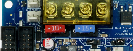
        All OUTS should be connected. The fuses are blade fuses like on cars, you can see them on the product image on the same page I linked to (the two pieces marked 10 and 15):

        a0ade8d9-5a98-4cfa-92d8-592b0115c0c7-image.png

        <>RatRig V-Minion Fly Super5Pro RRF<> V-Core 3.1 IDEX k*****r <> RatRig V-Minion SKR 2 Marlin<>

        SpeedyDadundefined 1 Reply Last reply Reply Quote 1
        • gloomyandyundefined
          gloomyandy @SpeedyDad
          last edited by

          @SpeedyDad How are you measuring the voltage? In particular what pin/connector are you using for the negative side of the measurement?

          SpeedyDadundefined 1 Reply Last reply Reply Quote 0
          • SpeedyDadundefined
            SpeedyDad @oliof
            last edited by

            @oliof Yup. Both fuses are visually fine and tested for continuity.

            1 Reply Last reply Reply Quote 0
            • SpeedyDadundefined
              SpeedyDad @gloomyandy
              last edited by SpeedyDad

              @gloomyandy Testing with a multimeter. Positive lead on the positive pin and negative lead on the negative pin f each of the OUT connectors. The positive leads are the ones closest to the side of the board with the VIN screw terminals.

              gloomyandyundefined 1 Reply Last reply Reply Quote 0
              • gloomyandyundefined
                gloomyandy @SpeedyDad
                last edited by

                @SpeedyDad The negative side of those connectors are switched so will be floating if you have not programmed them to be on. If you want to check for a +ve voltage on the out +ve pin use the main board gnd for the -ve side of your multimeter.

                SpeedyDadundefined 2 Replies Last reply Reply Quote 0
                • SpeedyDadundefined
                  SpeedyDad @gloomyandy
                  last edited by SpeedyDad

                  @gloomyandy Ah, thanks. That explains it. Still used to my DuetWifi where everything is just on. It is for my board fan so maybe I'll just simplify it and wire it directly to the main VIN and GND.

                  1 Reply Last reply Reply Quote 0
                  • SpeedyDadundefined
                    SpeedyDad @gloomyandy
                    last edited by SpeedyDad

                    @gloomyandy said in Duet 3 Mini 5+ no 24v on OUT 1 2 5 6:

                    @SpeedyDad The negative side of those connectors are switched so will be floating if you have not programmed them to be on. If you want to check for a +ve voltage on the out +ve pin use the main board gnd for the -ve side of your multimeter.

                    OK, sorry for being a noob but how do I "switch" the negative pin on? I've looked through the documentation but must have missed it.

                    I tried the M950 followed by the M106 but get "Error: Pin 'out5' is not free"

                    A Former User? 1 Reply Last reply Reply Quote 0
                    • A Former User?
                      A Former User @SpeedyDad
                      last edited by

                      This post is deleted!
                      SpeedyDadundefined 1 Reply Last reply Reply Quote 0
                      • SpeedyDadundefined
                        SpeedyDad @A Former User
                        last edited by

                        @Herve_Smith said in Duet 3 Mini 5+ no 24v on OUT 1 2 5 6:

                        @SpeedyDad said in Duet 3 Mini 5+ no 24v on OUT 1 2 5 6:

                        OK, sorry for being a noob but how do I "switch" the negative pin on? I've looked through the documentation but must have missed it.

                        I tried the M950 followed by the M106 but get "Error: Pin 'out5' is not free"

                        looks like you are attempting to control a fan, if so This documentation should help you

                        Yes, I know that. That's where I got the info to use M950 and M106 as stated above

                        A Former User? 1 Reply Last reply Reply Quote 0
                        • A Former User?
                          A Former User @SpeedyDad
                          last edited by

                          This post is deleted!
                          SpeedyDadundefined 1 Reply Last reply Reply Quote 0
                          • SpeedyDadundefined
                            SpeedyDad @A Former User
                            last edited by

                            @Herve_Smith said in Duet 3 Mini 5+ no 24v on OUT 1 2 5 6:

                            @SpeedyDad said in Duet 3 Mini 5+ no 24v on OUT 1 2 5 6:

                            @Herve_Smith said in Duet 3 Mini 5+ no 24v on OUT 1 2 5 6:

                            @SpeedyDad said in Duet 3 Mini 5+ no 24v on OUT 1 2 5 6:

                            OK, sorry for being a noob but how do I "switch" the negative pin on? I've looked through the documentation but must have missed it.

                            I tried the M950 followed by the M106 but get "Error: Pin 'out5' is not free"

                            looks like you are attempting to control a fan, if so This documentation should help you

                            Yes, I know that. That's where I got the info to use M950 and M106 as stated above

                            then please show the EXACT code you have created from reading that so we can see what you have done.

                            Pretty much copy/pasted the lines from the connecting a fan page and substituted my fan number and the pin number.

                            M950 F2 C"out5" Q500 ; create fan 0 on pin out3 and set its frequency
                            M106 P2 S0 H-1 ; set fan 0 value. Thermostatic control is turned off

                            A Former User? 1 Reply Last reply Reply Quote 0
                            • A Former User?
                              A Former User @SpeedyDad
                              last edited by

                              This post is deleted!
                              1 Reply Last reply Reply Quote 0
                              • First post
                                Last post
                              Unless otherwise noted, all forum content is licensed under CC-BY-SA