Duet3D Logo Duet3D
    • Tags
    • Documentation
    • Order
    • Register
    • Login
    1. Home
    2. SpeedyDad
    • Profile
    • Following 0
    • Followers 0
    • Topics 28
    • Posts 150
    • Best 10
    • Controversial 0
    • Groups 0

    SpeedyDad

    @SpeedyDad

    13
    Reputation
    3
    Profile views
    150
    Posts
    0
    Followers
    0
    Following
    Joined Last Online
    Location Chandler, AZ USA

    SpeedyDad Unfollow Follow

    Best posts made by SpeedyDad

    • RE: Revo Voron PZ Probe firmware configuration?

      Success! After restarting the printer, I was also getting errors "G90: Probe was not triggered during probing move" after it finished its homing moves. I looked in homeall.z and it ended in a G90. That really shouldn't have impacted it so I commented it out and ran it again. This time, no errors. To test it again, I removed the ; to comment it out and it still ran fine. No errors. Go figure. I am now able to get it to home properly, do a 4 motor gantry level and run mesh compensation. Mesh compensation takes forever now because it probes the bed twice at each point and, over a 400mm square bed, that takes a lot of time. I'll tweak its settings.

      Thanks all for the help. This forum is one of the best out there for solving issues.

      posted in General Discussion
      SpeedyDadundefined
      SpeedyDad
    • Chasing my tail with Auto dual Z leveling - Lesson learned

      I'm posting this in hopes someone else will learn from my trials.

      I have a home designed and built Prusa i3 derivative using aluminum extrusions for rigidity. As such, it has dual Z motors.

      I had been trying to get the auto dual Z leveling working and just kept getting errors or each time I tried, the bed would get more out of level. I disabled it for a while in frustration.

      Tonight, I went back to look at it again. Same results. The bed would just get more unlevel every time. I was just sitting staring at it and it finally hit me what was wrong. My dual Z motors are run off separate drivers (Drivers 2 and 4), not ganged together in the dual Z plug (Drivers 2 and B). When I built it, I paid no attention to which motor was in 2 and which was in 4. Many of you will just say "DUH!" but, again, I'm hoping this helps someone out. I had them reversed between 2 and 4. The software was working but sending the correction to the opposite motor, therefore making it worse. Face palm. I reversed them and all is well now and auto Z leveling works great.

      posted in Duet Hardware and wiring
      SpeedyDadundefined
      SpeedyDad
    • RE: Mini 5+ Odd fan behavior and now nothing. Blown Out3 and Out4?

      @jay_s_uk OK, that explains it. Thanks

      As far as the rest go, I feel really stupid now. Out3 and Out4 are fine. Somewhere along the way in testing, I must have confused the two connectors and I was testing with the lead which I believed to be the part fan. It was not. It was the lead going to the disconnected hotend fan. Dumb! I made an assumption and it bit me. That and the misunderstanding about "Tool Fan" led me down the wrong path.

      posted in Duet Hardware and wiring
      SpeedyDadundefined
      SpeedyDad
    • Enable Auto-Sleep

      I've looked around the online documentation and did a search of the forum but can't find the answer to this. What does the "Enable Auto-Sleep" function do?

      Thanks

      posted in General Discussion
      SpeedyDadundefined
      SpeedyDad
    • RE: Error trying to install Input Shaping plugin

      OK, Got it. I figured it was a "I'm on a Mac" thing. Instead of just downloading the file, I right-click on the download link and did a "save As". It downloaded it with a longer name and that zip file worked fine.

      posted in Firmware installation
      SpeedyDadundefined
      SpeedyDad
    • RE: Filament monitor dimensions and step files

      Found the files from Duet. I was in the instructions and found you have to click on the "kit" instructions. They are in there. I'll print out the factory version and go from there using the dimensions there.

      posted in Duet Hardware and wiring
      SpeedyDadundefined
      SpeedyDad
    • RE: Enable Auto-Sleep

      Thanks. Maybe I can figure out how to have it turn itself off.

      posted in General Discussion
      SpeedyDadundefined
      SpeedyDad
    • RE: Toolboard 1LC connectors and tool?

      @jay_s_uk said in Toolboard 1LC connectors and tool?:

      @SpeedyDad https://docs.duet3d.com/en/User_manual/Troubleshooting/Parts#connectors-used-on-duet-3-toolboard-1lc

      Ya know, I read that area and it just didn't communicate to my brain. LOL. Thanks.

      posted in Duet Hardware and wiring
      SpeedyDadundefined
      SpeedyDad
    • RE: X and Y axis stopping and starting

      @jay_s_uk Yup, that was it. Thanks! It's odd. I can't recall ever changing that but it is possible.

      posted in General Discussion
      SpeedyDadundefined
      SpeedyDad
    • RE: Toolboard 1LC connectors and tool?

      I actually figured out my problem. I have a couple crimping tools I use for RC stuff (servo wires, etc). Nice ratcheting ones. When I would crimp the wire, the wire would break where the insulation was crimped. After looking at it, I found the long legs of the connector itself that are supposed to crimp the wire insulation was curling in on itself and cutting the wire. My remedy was to cut the little legs shorter. No problems now.

      posted in Duet Hardware and wiring
      SpeedyDadundefined
      SpeedyDad

    Latest posts made by SpeedyDad

    • RE: Paneldue issues since updating to DWC 3.5.4

      @Phaedrux said in Paneldue issues since updating to DWC 3.5.4:

      @SpeedyDad said in Paneldue issues since updating to DWC 3.5.4:

      so I updated it to 1.25 which is, I believe, the latest the older one can be updated to.

      It depends how much flash memory you actually have on it. My v2 is able to run the latest paneldue firmware for instance, so it may be worth trying to update.

      Yeah, like I said above, I tried it. No luck. Not enough flash storage.

      posted in Firmware installation
      SpeedyDadundefined
      SpeedyDad
    • RE: Paneldue issues since updating to DWC 3.5.4

      @droftarts said in Paneldue issues since updating to DWC 3.5.4:

      @SpeedyDad Sounds like you have a PanelDue V2 from before August 2016, when the flash memory size was increased. PanelDue v1.25 firmware won't work with current RRF versions, because the method of communication has changed (it queries the Object Model now, rather than using M408), and the encoding has changed (now CRC). Time for a new PanelDue, unfortunately. The screen itself may still be usable, so you could replace the V2 with a V3 PanelDue.

      Ian

      I was afraid of that. I guess that is the cost of progress.

      posted in Firmware installation
      SpeedyDadundefined
      SpeedyDad
    • Paneldue issues since updating to DWC 3.5.4

      I upgraded my Duet Mini 5+ to DWC 3.5.4 and now, my Paneldue (v2.0 7") won't finish starting up. It gets to the stage of showing that HTTP is enabled but it just sits there after that. I can touch buttons like to home iit and they beep but do nothing. It only shows the bed temp and the upper righthand corner just says starting up. It was on firmware 1.1 so I updated it to 1.25 which is, I believe, the latest the older one can be updated to. Is that correct or did I misinterpret that. I did try the latest version as well but that won't install. Just says not enough flash space.

      Thoughts?

      posted in Firmware installation
      SpeedyDadundefined
      SpeedyDad
    • RE: Revo Voron PZ Probe firmware configuration?

      Success! After restarting the printer, I was also getting errors "G90: Probe was not triggered during probing move" after it finished its homing moves. I looked in homeall.z and it ended in a G90. That really shouldn't have impacted it so I commented it out and ran it again. This time, no errors. To test it again, I removed the ; to comment it out and it still ran fine. No errors. Go figure. I am now able to get it to home properly, do a 4 motor gantry level and run mesh compensation. Mesh compensation takes forever now because it probes the bed twice at each point and, over a 400mm square bed, that takes a lot of time. I'll tweak its settings.

      Thanks all for the help. This forum is one of the best out there for solving issues.

      posted in General Discussion
      SpeedyDadundefined
      SpeedyDad
    • RE: Revo Voron PZ Probe firmware configuration?

      @crpalmer said in Revo Voron PZ Probe firmware configuration?:

      @SpeedyDad said in Revo Voron PZ Probe firmware configuration?:

      Your wire connections look correct. The PZ PCB is reading the piezo probe correctly. But the firmware is not correctly reading the triggered value. That would most likely be a bad crimp or a misconfiguration. I think it's the misconfiguration because you have:

      M558 P8 C"!^io1.in" A5 R1 H5 F400 T24000
      

      which would be the io1.in pin on the main board. The toolboard would be xxx.io1.in where "xxx" is the canbus address of the board. From the comments around the zprobe and previous posts you've made, I'm guess that it should be:

      M558 P8 C"!^121.io1.in" A5 R1 H5 F400 T24000
      

      Ah, good catch. It was set to 121 but I changed it and forgot the 121. Now, it does register a 1000 when the probe is touched and I was able to run G30 S-1 once. After that, trying to run it again got the error:

      "G30 S-1
      Error: G30: Probe was not triggered during probing move"

      Some leftover stuff from trying to probe with the BLTouch I'd imagine. Progress is being made though.

      posted in General Discussion
      SpeedyDadundefined
      SpeedyDad
    • RE: Revo Voron PZ Probe firmware configuration?

      @crpalmer said in Revo Voron PZ Probe firmware configuration?:

      @SpeedyDad Two of the machines are running the latest stable (3.5.4?) and the idex printer is running 3.6.0-rc2+2 (for a bug fix needed to calibrate the tool offsets).

      it sounds like you're not getting anywhere. I would suggest that you do the following:

      • post your full config.g
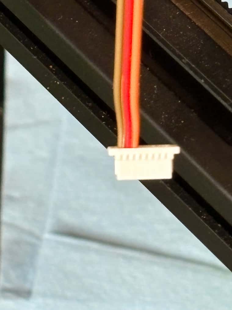
      • try to get a good picture of the wire connections at the pz probe pcb and the toolboard pcb to show how it is wired (and post it here)
      • verify that when you tap the nozzle, the triggered light on the pz probe flashes
      • verify that when everything is idle that the probe status shows 0
      • verify that when you tap the nozzle, the probe status flashes to 1000

      If one of those things don't work, that's the first problem you need to fix.

      if all that works, then I would manually (or via a G92 Z0 G1 Zxx) make sure that you have a large space between your nozzle and your print bed and then run G30 S-1. Let the probe run a for a couple of seconds to make sure it isn't false triggering and then tap the nozzle. If it doesn't stop, hit emergency stop.

      If you want to try those steps and report back along with your full config.g, I (or someone else) may have a suggestion.

      OK, Here are the results of above:
      My connections to the Roto toolboard are as follows. Red from the PZ Board = io1 +3.3v. Orange from PZ Board = io1.in. Brown from PZ Board = GND. I have verified continuity at both ends of the signal wire.
      IMG_1344.jpg
      IMG_1347.jpg
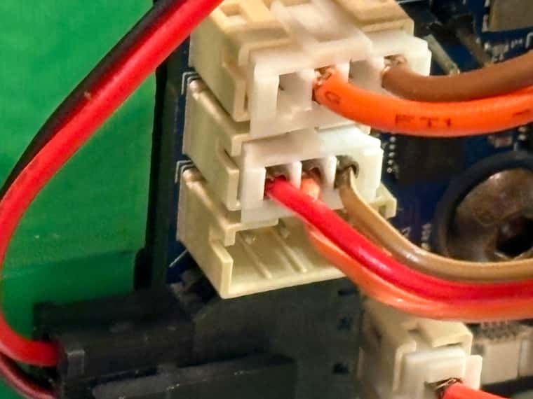
      I get a power LED on the PZ Board.
      I get a flash of the amber LED when I tout the nozzle end.
      Probe shows as 0 on the panel when idle.
      Probe does not flash to 1000 during trigger
      Running a G30 S-1 and tapping the probe does nothing.

      My config.g
      ; Configuration file for Duet 3 Mini 5+ (firmware version 3.3)
      ; executed by the firmware on start-up
      ;
      ; generated by RepRapFirmware Configuration Tool v3.4.1 on Sat Aug 17 2024 21:55:35 GMT-0700 (Mountain Standard Time)

      ; General preferences
      M575 P1 S1 B57600 ; enable support for PanelDue
      G90 ; send absolute coordinates...
      M83 ; ...but relative extruder moves
      M550 P"Voron" ; set printer name
      M669 K1 ; select CoreXY mode

      ; Wait a moment for the CAN expansion boards to start
      G4 S2

      ; Network
      M552 S1 ; enable network
      M586 P0 S1 ; enable HTTP
      M586 P1 S0 ; disable FTP
      M586 P2 S0 ; disable Telnet

      ; Accelerometers
      M955 P121.0 I20 ; configure accelerometer on board #20

      ; Drives
      M569 P0.0 S0 D2 ; driver 0.0 goes backwards (X axis)
      M569 P0.1 S0 D2 ; driver 0.1 goes backwards (Y axis)
      M569 P0.2 S0 D2 ; driver 0.2 goes backwards (Z axis)
      M569 P0.3 S1 D2 ; driver 0.3 goes forwards (Z axis)
      M569 P0.4 S0 D2 ; driver 0.4 goes backwards (Z axis)
      M569 P0.5 S1 D2 ; driver 0.5 goes forwards (Z axis)
      M569 P121.0 S0 D2 ; driver 20.0 goes backwards (extruder 0)

      ; Axes
      M584 X0.0 Y0.1 Z0.2:0.3:0.4:0.5 ; set axis mapping
      M671 X-70:-70:470:470 Y20:455:455:20 S10 ; position of leadscrew/bed pivot point at front left, rear left, rear right and front right
      M350 X16 Y16 Z16 I1 ; configure microstepping with interpolation
      M906 X1700 Y1700 Z1700 ; set axis driver currents
      M92 X80 Y80 Z400 ; configure steps per mm
      M208 X-15:400 Y0:390 Z0:400 ; set minimum and maximum axis limits
      M566 X100 Y100 Z60
      M203 X20000 Y20000 Z3600 ; set maximum speeds (mm/min)
      M201 X8000 Y8000 Z30

      ; Extruders
      M584 E121.0 ; set extruder mapping
      M350 E16 I1 ; configure microstepping with interpolation
      M906 E1000 ; set extruder driver currents
      M92 E397 ; configure steps per mm
      M566 E150 ; set maximum instantaneous speed changes (mm/min)
      M203 E3600 ; set maximum speeds (mm/min)
      M201 E1500 ; set accelerations (mm/s^2)

      ; Motor Idle Current Reduction
      M906 I30 ; set motor current idle factor
      M84 S30 ; set motor current idle timeout

      ; Endstops
      M574 X2 S1 P"121.io2.in" ; configure switch-type (e.g. microswitch) endstop for high end on X via pin io0.in
      M574 Y2 S1 P"io2.in" ; configure switch-type (e.g. microswitch) endstop for high end on Y via pin io2.in
      M574 Z1 S2

      ; Z-Probe
      ;M950 S0 C"121.io0.out" ; create servo pin 0 for BLTouch
      ;M558 K0 P8 C"^!io1.in" R1.0 H5 F400 A5 T24000
      ;G31 P500 X0 Y0 Z0 ; set Z probe trigger value, More Z = Closer
      M558 P8 C"!^io1.in" A5 R1 H5 F400 T24000
      G31 X0 Y0 Z0 P100
      M575 P1 B9600 S7

      ; Mesh Bed Compensation
      M557 X20:400 Y30:380 S40 ; define mesh grid

      ; Heaters
      ;Bed
      M308 S0 P"temp0" Y"thermistor" T100000 B4550 C0 A"Bed" ; configure sensor 0 as thermistor on pin temp0
      M950 H0 C"out0" T0 ; create bed heater output on out0 and map it to sensor 0
      M307 H0 R0.203 K0.232:0.000 D2.45 E1.35 S1.00 B0
      M140 H0 ; map heated bed to heater 0
      M143 H0 S120
      ;Hotend
      M308 S1 P"121.temp0" Y"thermistor" A"Hotend" T100000 B4725 C7.060000e-8 ; configure sensor 1 as thermistor on pin 20.temp0
      M950 H1 C"121.out0" T1 ; create nozzle heater output on 20.out0 and map it to sensor 1
      M307 H1 B0 S1.00 ; disable bang-bang mode for heater and set PWM limit
      M143 H1 S280 ; set temperature limit for heater 1 to 280C

      ; Fans
      M950 F0 C"121.out1" ; create fan #0
      M106 P0 C"Part Fan" S0 L0 X1 B0.1 ; configure fan #0
      M950 F1 C"121.out2" ; create fan #1
      M106 P1 C"Hotend Fan" S0 B0.1 H1 T45 ; configure fan #1

      ; Tools
      M563 P0 D0 H1 F0 ; define tool 0
      G10 P0 X0 Y0 Z0 ; set tool 0 axis offsets
      G10 P0 R0 S0 ; set initial tool 0 active and standby temperatures to 0C

      T0

      ; Custom settings are not defined

      ; Miscellaneous
      M501 ; load saved parameters from non-volatile memory
      M911 S10 R11 P"M913 X0 Y0 G91 M83 G1 Z3 E-5 F1000" ; set voltage thresholds and actions to run on power loss

      posted in General Discussion
      SpeedyDadundefined
      SpeedyDad
    • RE: Revo Voron PZ Probe firmware configuration?

      Sorry all. Got a little busy with other things. I'll work on this with the above suggestions in the AM. I appreciate the help.

      posted in General Discussion
      SpeedyDadundefined
      SpeedyDad
    • RE: Revo Voron PZ Probe firmware configuration?

      @crpalmer said in Revo Voron PZ Probe firmware configuration?:

      @SpeedyDad Yes, I have a PZ Probe connected to a (regular, not roto) Toolboard, two running on an IDEX printer with a 3HCL expansion board (I use them to calibrate the tool offsets when starting a multi-material/colour print) and one on another printer just plugged into the regular control board. All of them are working great and I have plans to install more of them.

      What firmware version are you running?

      posted in General Discussion
      SpeedyDadundefined
      SpeedyDad
    • RE: Revo Voron PZ Probe firmware configuration?

      @crpalmer said in Revo Voron PZ Probe firmware configuration?:

      @SpeedyDad I wasn't suggesting that you change the input pin (it depends on where you have the pz probe connected). Your original M558 was:

      M558 P8 C"121.io0.in" H10 F700 T16000
      

      and I was suggesting that you could change it to something like:

      M558 K0 P8 C"^!121.io0.in" H10 F700 T16000
      M558 K0 P8 C"^!121.io0.in" R0.5 H5 F400 A2 T24000
      M558 K0 P8 C"^!121.io0.in" R1.0 H5 F400 A5 T24000
      

      E3D is also suggesting that you turn off the heaters (the B1) but I don't do that and it has been working well for me.

      All that said, if you have the correct pin in the M558 command with ^! and it shows not triggered when idle but when you tap the hotend the www interface doesn't show the z probe triggered then you have a problem. You can post your config.g and maybe I (or someone) can suggest a problem. Also, are you sure your crimps are good?

      The "commands section" is for non-standard usage of the probe or to reprogram the settings. You can ignore that until you find you want to do one of those things.

      Yeah, I understood what you were saying. The changing the pin was just in case it didn't like the io0 input. I tried your example and theirs. Is yours up and running?

      posted in General Discussion
      SpeedyDadundefined
      SpeedyDad
    • RE: Revo Voron PZ Probe firmware configuration?

      @crpalmer said in Revo Voron PZ Probe firmware configuration?:

      @SpeedyDad Your M558 looks like the problem...

      Nope. Switching to io1.in did not help. Still will not trigger the endstop. I have tried it with and without the "M574 Z1 S2" in the endstop section. At least with the M574 Z1 S2, it recognizes that I have a probe and an endstop.

      This is what it says in the E3D duet configuration page:
      ; From Duet 3.6.0 onwards

      ; Z Probe - Piezo

      M574 Z1 P"nil" ; For Duet 2 with RRF3 only, free up z-probe before reassigning it.
      M558 P8 C"^!zstop" R0.5 F400 B1 A2 H5 ; analogue mode, 0.5 sec delay, 400mm/min dive speed, turn off heater during probing, two probes per point, 5mm Dive Height.
      G31 X0 Y0 Z0 P100 ; Set probe offset from XYZ to Zero
      M575 P1 B9600 S7 ; Set baudrate on paneldue connector (where Piezo is connected) and set into device mode

      ; Commands can be sent as follows:
      ; Write: M260.2 P1 S"STATUS\n" ; Use the commands as shown in the PZ-Probe documentation. \n is required at the end of the command.
      ; Read: M261.2 P1 B10 ; Only a set number of bytes (B) can be read at anytimes, so the command will need to be repeated several times and the B value may have to be changed to read the whole data packet recieved. The values returned are in Hex, so these will need to be converted to ASCII to read the data.

      Does this not work unless connected to the PanelDue connector on the mainboard? Not sure what to do with the stuff in the Commands section. BTW - this did not appear before when I went to their page. There was no link. I sent them an email asking for config info. Maybe my email caused them to fix that. Anyways, does this mean it will only work in 3.6.0?

      posted in General Discussion
      SpeedyDadundefined
      SpeedyDad