Error: G0/G1: insufficient axes homed
-
Hi everyone,
If there is anyone out there that could shed some light on this I would be eternally grateful!
I have a Troodon 2.0 ( basically a voron 2.4 ish ) with Duet 3.4.5. I will post a diagnostic, config files and home files below.
I just can't seem to home any of my axis, when ever I do I get a "Error: G0/G1: insufficient axes homed" message. I am pretty sure the issue is firmware based, although the issue did occur when I installed a new tool head and updated firmware at the same time ( i am unable to revert back to original firmware ), so can't be 100% it isn't hardware based or a mixture of the two.
I do know that all endstops and z probes are working correctly, tested via M119
If there is anyone that can spot why in any of the info below, I would really appreciate some help with this.
Thanks
DavidDiagnostic:
M122
=== Diagnostics ===
RepRapFirmware for STM32F4 based Boards (troodon_v2) version 3.4.6_101 (2023-08-01 13:29:03) running on STM32F4
Board ID: W10Q2-0427A-D6MUJ-6Q1FG-G6GUS-70000
Used output buffers: 2 of 40 (24 max)
=== RTOS ===
Static ram: 19548
Dynamic ram: 84468 of which 0 recycled
Never used RAM 26028, free system stack 147 words
CCMRam static ram: 16760 dynamic ram: 23172 free ram 25600
Tasks: NETWORK(notifyWait,13.0%,263) HEAT(notifyWait,0.0%,347) Move(notifyWait,0.0%,316) TMC22xx(notifyWait,0.0%,149) FSWRITE(notifyWait,0.0%,474) MAIN(running,86.9%,434) IDLE(ready,0.1%,29), total 100.0%
Owned mutexes: WiFi(NETWORK)
=== Platform ===
Last reset 00:12:45 ago, cause: power on/off
Last software reset at 2023-11-25 11:56, reason: User, GCodes spinning, available RAM 25836, slot 0
Software reset code 0x0003 HFSR 0x00000000 CFSR 0x00000000 ICSR 0x00400000 BFAR 0xe000ed38 SP 0x00000000 Task MAIN Freestk 0 n/a
Error status: 0x00
Step timer max interval 0
MCU temperature: min 48.0, current 48.2, max 48.4
Supply voltage: min 24.0, current 24.0, max 24.0, under voltage events: 0, over voltage events: 0, power good: yes
Heap OK, handles allocated/used 99/14, heap memory allocated/used/recyclable 2048/286/0, gc cycles 0
Events: 1 queued, 1 completed
Driver 0: not present
Driver 1: not present
Driver 2: not present
Driver 3: not present
Driver 4: not present
Driver 5: not present
Driver 6: not present
Driver 7:
Driver 8:
Driver 9:
Driver 10:
Driver 11:
Driver 12:
Driver 13:
Date/time: 2023-11-25 12:50:56
Slowest loop: 2.46ms; fastest: 0.09ms
=== Storage ===
Free file entries: 10
SD card 0 detected
SD card longest read time 0.0ms, write time 0.0ms, max retries 0
=== Move ===
DMs created 83, segments created 3, maxWait 0ms, bed compensation in use: none, comp offset 0.000
=== MainDDARing ===
Scheduled moves 2, completed 2, hiccups 0, stepErrors 0, LaErrors 0, Underruns [0, 0, 0], CDDA state -1
=== AuxDDARing ===
Scheduled moves 0, completed 0, hiccups 0, stepErrors 0, LaErrors 0, Underruns [0, 0, 0], CDDA state -1
=== Heat ===
Bed heaters 0 -1 -1 -1, chamber heaters -1 -1 -1 -1, ordering errs 0
Heater 1 is on, I-accum = 0.0
=== GCodes ===
Segments left: 0
Movement lock held by null
HTTP is idle in state(s) 0
File is idle in state(s) 0
USB is idle in state(s) 0
Aux is idle in state(s) 0
Trigger is idle in state(s) 0
Queue is idle in state(s) 0
LCD is idle in state(s) 0
Daemon is idle in state(s) 0
Autopause is idle in state(s) 0
Code queue is empty
=== Filament sensors ===
Extruder 0 sensor: no filament
=== Network ===
Slowest loop: 40.53ms; fastest: 0.08ms
Responder states: HTTP(0) HTTP(0) HTTP(0) HTTP(0) FTP(0)
HTTP sessions: 1 of 8
Uploads/Errors: 0/0
= WiFi =
Interface state: active
Module is connected to access point
Failed messages: pending 0, notready 0, noresp 0
Bad header: 2/0
WiFi firmware version 1.26-08S32-D
WiFi MAC address b8:69:f4:49:d7:17
WiFi Vcc 0.00, reset reason Power up
WiFi flash size 0, free heap 147672
WiFi IP address 192.168.88.247
WiFi signal strength -46dBm, mode 802.11n, reconnections 0, sleep mode none
Clock register 00000000
Socket states: 0 0 0 0 0 0 0 0Home X
G91 ; relative positioning
G1 H2 Z10 F6000 ; lift Z relative to current position
if sensors.endstops[0].triggered = true ; if we're hard against the endstop we need to move away
M564 H0 S0
G1 X-20 F1200
M564 H1 S1
M400
if sensors.endstops[0].triggered = true
abort "X Endstop appears to be faulty. Still in triggered state."
G1 H1 X355 F6000 ; move quickly to X axis endstop and stop there (first pass)
if result != 0
abort "Print cancelled due error during fast homing"
G1 X-5 F6000 ; go back a few mm
G1 H1 X355 F360 ; move slowly to X axis endstop once more (second pass)
if result != 0
abort "Print cancelled due to error during slow homing"
G1 X-5 F6000 ; go back a few mm
G1 H2 Z-10 F6000 ; lower Z again
G90 ; absolute positioningHome Y:
G91 ; relative positioning
G1 H2 Z10 F6000 ; lift Z relative to current position
if sensors.endstops[1].triggered = true ; if we're hard against the endstop we need to move away
M564 H0 S0
G1 Y-20 F1200
M564 H1 S1
M400
if sensors.endstops[1].triggered = true
abort "Y Endstop appears to be faulty. Still in triggered state."
G1 H1 Y355 F6000 ; move quickly to Y axis endstop and stop there (first pass)
if result != 0
abort "Print cancelled due error during fast homing"
G1 Y-5 F6000 ; go back a few mm
G1 H1 Y355 F360 ; move slowly to Y axis endstop once more (second pass)
if result != 0
abort "Print cancelled due to error during slow homing"
G1 Y-5 F6000 ; go back a few mm
G1 H2 Z-10 F6000 ; lower Z again
G90 ; absolute positioningHome z:
if !move.axes[0].homed || !move.axes[1].homed ; If the printer hasn't been homed, home it
G28 XY ; home y and x
G91 ; relative positioning
G1 H2 Z10 F6000 ; lift Z relative to current position
G90 ; absolute positioning
G1 X{(move.axes[0].min + move.axes[0].max)/2 - sensors.probes[0].offsets[0]} Y{(move.axes[1].min + move.axes[1].max)/2 - sensors.probes[0].offsets[1]} F3600 ; Move to the centre of the bed taking the zprobe offsets into account
M558 K0 H10 ; Set the dive height for the probe to 10mm
M568 P0 S{global.nozzleProbeTemperature} A2 ; if cold set the nozzle temperature to 175 degrees
M116 P0 ; wait for the nozzle to reach temperature
G30 ; probe the bed
if !exists(param.A) ; check if param.A doesn't exist
M568 P0 S0 A0 ; turn the hotend offConfig:
;#################### Version ###########################
;The overall version of this "improved" version is 1.6.3-1;#################### General preferences ###############
G90 ; send absolute coordinates...
M83 ; ...but relative extruder moves
M550 P"Troodon 2" ; set printer name
M669 K1 ; select CoreXY mode;#################### Network ###########################
M552 S1 ; enable network
M586 P0 S1 ; enable HTTP
M586 P1 S0 ; disable FTP
M586 P2 S0 ; disable Telnet;#################### Axis Mapping ######################
; --- drive map ---
; _______
; | 3 | 6 |
; | ----- |
; | 4 | 5 |
; -------
; front
M584 X0 Y1 Z4:3:6:5 E2 ; set drive mapping;#################### Drives ############################
M569 P0 S1 ; physical drive 0 goes forwards using default driver timings
M569 P1 S1 ; physical drive 1 goes forwards using default driver timings
M569 P2 S1 ; physical drive 2 goes forwards using default driver timings
M569 P3 S0 ; physical drive 3 goes forwards using default driver timings
M569 P4 S1 ; physical drive 4 goes forwards using default driver timings
M569 P5 S0 ; physical drive 5 goes forwards using default driver timings
M569 P6 S1 ; physical drive 6 goes forwards using default driver timings
M350 X16 Y16 Z16 E16 I1 ; configure microstepping with interpolation
M92 X80.00 Y80.00 Z400.00 ; set steps per mm
M92 E417.00 ; Stock steps per mm
;M92 E710.00 ; SB steps per mm. Uncomment if using Formbot SB kit and comment out line above
M566 X600 Y600 Z600 E600 ; maximum instantaneous speed changes (mm/min) (jerk)
M203 X30000 Y30000 Z4000 E5000 ; maximum speeds (mm/min)
M201 X2000 Y2000 Z650 E3200 ; accelerations
M906 X1600 Y1600 Z1600 I30 ; set motor currents (mA) and motor idle factor in per cent
M906 E640 ; Stock motor current
;M906 E800 ; SB Motor Current. Uncomment if using Formbot SB kit and comment out line above
M84 S30 ; Set idle timeout;#################### Axis Limits #######################
M208 X0 Y0 Z0 S1 ; set axis minima
M208 X348 Y353 Z320 S0 ; set axis maxima
M671 X-50:-50:405:405 Y-75:355:355:-75 S20 ; set gantry pivot points;#################### Endstops ##########################
M574 X2 S1 P"xstop" ; configure switch-type (e.g. microswitch) endstop for low end on X via pin xstop
M574 Y2 S1 P"ystop" ; configure switch-type (e.g. microswitch) endstop for low end on Y via pin ystop;#################### Print Head Probe ##################
M558 K0 P5 C"probe" T12000 F300:120 H10 A10 S0.01 ; configure the probe on the print head
G31 K0 P500 X0 Y0 Z-0.5 ; set Z probe X, Y and Z offsets
M557 X10:345 Y10:330 P10 ; define mesh grid;#################### Nozzle Probe ######################
M558 K1 P8 C"zstop" T18000 F180 H5 A10 S0.0025 R0 ; configure the probe used by autoz
G31 K1 P500 X0 Y0 Z3 ; set autoZ probe X, Y and Z offsets;#################### Heaters ###########################
M308 S0 P"bedtemp" Y"thermistor" T100000 B3950 ; configure sensor 0 as thermistor on pin bedtemp
M950 H0 C"bed" T0 Q10 ; create bed heater output on bed and map it to sensor 0
M140 H0 ; map heated bed to heater 0
M143 H0 S130 ; set temperature limit for heater 0 to 125CM308 S1 P"e0temp" Y"pt1000" ; configure sensor 1 as thermistor on pin e0temp
M950 H1 C"e0heat" T1 ; create nozzle heater output on e0heat and map it to sensor 1
M307 H1 A517.3 C213.3 D11.1 V24 B0 ; disable bang-bang mode for heater and set PWM limit
M143 H1 S460 ; set temperature limit for heater 1 to 460CM308 S10 Y"mcu-temp" A"MCU" ; defines sensor 10 as MCU temperature sensor
;#################### Fans ##############################
M950 F0 C"fan1" Q500 ; create fan 0 on pin fan0 and set its frequency
M106 P0 S0 H-1 C"Part Cooling" ; set fan 0 value. Thermostatic control is turned ON
M950 F1 C"fan0" Q500 ; create fan 1 on pin out8 and set its frequency
M106 P1 S1 H1 T50 C"Hotend Fan" ; set fan 1 value. Thermostatic control is turned off
M950 F2 C"fan2" Q40 ; create fan 2 on pin out8 and set its frequency
M106 P2 S0 H-1 C"Chamber Fan" ; set fan 2 value. Thermostatic control is turned off
M950 F3 C"fan3" Q500 ; create fan 3 on pin fan0 and set its frequency
M106 P3 S0 H-1 C"Electronics Fan" ; set fan 3 value. Thermostatic control is turned ON
M950 F4 C"fan4" Q500 ; create fan 4 on pin out8 and set its frequency
M106 P4 S0 H-1 C"LED" ; set fan 4 value. Thermostatic control is turned off;#################### Tools #############################
M563 P0 D0 H1 F0 ; define tool 0
G10 P0 X0 Y0 Z0 ; set tool 0 axis offsets
G10 P0 R0 S0 ; set initial tool 0 active and standby temperatures to 0C;#################### Filament Sensor ###################
M591 D0 P1 C"e0stop" S1 ; define the filament sensor for D0;#################### Firmware Retraction ###############
M207 S0.5 F1800 Z0.2 ; 0.5mm retraction, 0.2mm Z hop;#################### Pressure Advance ##################
M572 D0 S0.045 ; define pressure advance for D0;#################### 12864 Screen ######################
M98 P"screen.g" ; run screen.g;#################### Load Settings from Config-override
M501 ; load overrides from config-override.g;#################### Globals ###########################
M98 P"globals.g" ; initialize global variablesT0 ; select tool 0
-
@ThreeDeeDave said in Error: G0/G1: insufficient axes homed:
Driver 0: not present
Driver 1: not present
Driver 2: not present
Driver 3: not present
Driver 4: not present
Driver 5: not present
Driver 6: not presentNone of your drivers have been detected, which is not a good start. Run the following command
M122 P200
and the output from that here. You are actually running 3.4.6, not 3.4.5. -
Thanks for taking a look.
Ah ok yes I see that can't be good. Ok please see results:M122 P200
=== Diagnostics ===
RepRapFirmware for STM32F4 based Boards (troodon_v2) version 3.4.6_101 running on STM32F4 at 168Mhz
Bootloader: Unknown== Supported boards ==
Board 0.0: generic iomode 254 Signatures:
Board 1.0: biquskrpro_1.1 iomode 0 Signatures: 0x768a39d6 0x50da391 0xa79a1917
Board 2.0: biqugtr_1.0 iomode 1 Signatures: 0x94a2cc03
Board 3.0: fly_e3_pro iomode 2 Signatures: 0xd0c680ae
Board 4.0: fly_e3_prov3 iomode 2 Signatures: 0xd0c680ae
Board 5.0: fly_f407zg iomode 2 Signatures: 0x8a5f5551 0xd0c680ae
Board 6.0: fly_e3 iomode 2 Signatures: 0xd0c680ae 0xfd2146b0
Board 7.0: fly_e3_v2 iomode 2 Signatures: 0xd0c680ae
Board 8.0: fly_cdyv2 iomode 2 Signatures: 0x8a5f5551 0xd0c680ae
Board 8.1: fly_cdyv3 iomode 2 Signatures: 0x8a5f5551 0xd0c680ae
Board 9.0: fly_super8 iomode 2 Signatures: 0x8a5f5551 0xd0c680ae
Board 10.0: fly_gemini iomode 2 Signatures: 0xbfecc997
Board 11.0: fly_geminiv1.1 iomode 1 Signatures: 0x318f4fbe
Board 12.0: fly_geminiv2.0 iomode 1 Signatures: 0x318f4fbe
Board 13.0: biquskr_rrf_e3_1.1 iomode 2 Signatures: 0x94a2cc03 0xb173b733
Board 14.0: biquskr_2 iomode 2 Signatures: 0xb75b00a7 0x35f4602c
Board 15.0: biqoctopus_1.1 iomode 2 Signatures: 0x5e29d842
Board 15.1: biquoctopus_1.1 iomode 2 Signatures: 0x5e29d842
Board 16.0: biqoctopuspro_1.0 iomode 2 Signatures: 0x5e29d842
Board 16.1: biquoctopuspro_1.0 iomode 2 Signatures: 0x5e29d842
Board 17.0: biquoctopus_x7 iomode 2 Signatures: 0x5e29d842
Board 17.1: troodon_v2 iomode 2 Signatures: 0x5e29d842
Board 18.0: fysetc_spider iomode 1 Signatures: 0x8479e19e
Board 19.0: fysetc_spider_king407 iomode 1 Signatures: 0xb86f16db== Configurable Board.txt Settings ==
board = troodon_v2 Signature 0xe826121bleds.diagnostic = C.7
leds.diagnosticOn = true
leds.activity = NoPin
leds.activityOn = true
pins.SetHigh = {NoPin, NoPin, NoPin, NoPin, NoPin, NoPin, NoPin, NoPin}
pins.SetLow = {NoPin, NoPin, NoPin, NoPin, NoPin, NoPin, NoPin, NoPin}
stepper.powerEnablePin = NoPin
stepper.enablePins = {A.1, C.1, C.5, E.10, E.15, F.12, G.1, NoPin, NoPin, NoPin, NoPin, NoPin, NoPin, NoPin}
stepper.stepPins = {A.3, C.2, B.0, E.11, B.10, F.13, E.7, NoPin, NoPin, NoPin, NoPin, NoPin, NoPin, NoPin}
stepper.directionPins = {A.4, C.3, B.1, E.12, B.11, F.14, E.8, NoPin, NoPin, NoPin, NoPin, NoPin, NoPin, NoPin}
stepper.digipotFactor = 0.00
stepper.TmcUartPins = {A.2, C.0, C.4, E.9, E.14, F.11, G.0, NoPin, NoPin, NoPin, NoPin, NoPin, NoPin, NoPin}
stepper.numSmartDrivers = 7
stepper.num5160Drivers = 0
stepper.spiChannel = 255
stepper.csDelay = 0
stepper.TmcDiagPins = {NoPin, NoPin, NoPin, NoPin, NoPin, NoPin, NoPin, NoPin, NoPin, NoPin, NoPin, NoPin, NoPin, NoPin}
heat.tempSensePins = {A.0, F.3, NoPin, NoPin, NoPin, NoPin, NoPin, NoPin, NoPin}
heat.spiTempSensorCSPins = {NoPin, NoPin, NoPin, NoPin, NoPin, NoPin, NoPin, NoPin}
heat.spiTempSensorChannel = 255
heat.thermistorSeriesResistor = 4700.00
atx.powerPin = NoPin
atx.powerPinInverted = false
atx.initialPowerOn = true
sdCard.internal.spiFrequencyHz = 25000000
sdCard.external.csPin = B.12
sdCard.external.cardDetectPin = D.8
sdCard.external.spiFrequencyHz = 4000000
sdCard.external.spiChannel = 1
lcd.lcdCSPin = G.3
lcd.lcdBeepPin = G.5
lcd.encoderPinA = D.10
lcd.encoderPinB = D.9
lcd.encoderPinSw = G.4
lcd.lcdDCPin = G.2
lcd.panelButtonPin = NoPin
lcd.spiChannel = 1
SPI0.pins = {A.5, A.6, A.7}
SPI1.pins = {B.13, B.14, B.15}
SPI2.pins = {B.3, B.4, B.5}
SPI3.pins = {NoPin, NoPin, NoPin}
SPI4.pins = {NoPin, NoPin, NoPin}
SPI5.pins = {NoPin, NoPin, NoPin}
8266wifi.espDataReadyPin = D.0
8266wifi.lpcTfrReadyPin = D.3
8266wifi.TfrReadyPin = D.3
8266wifi.espResetPin = G.14
8266wifi.csPin = A.15
8266wifi.serialRxTxPins = {D.6, D.5}
8266wifi.spiChannel = 2
8266wifi.clockReg = 0
serial.aux.rxTxPins = {NoPin, NoPin}
led.neopixelPin = D.14
power.VInDetectPin = NoPin
power.voltage = 24
accelerometer.spiChannel = 255== Defined Pins ==
e0temp,th0 = F.3
bedtemp,tb = A.0
xstop = F.2
ystop = C.15
zstop = C.13
e0stop,e0det = C.14
probe,PS1 = F.4
pro_sw,PS = G.7
bed = D.12
e0heat = B.9
fan0,fan = B.8
fan1 = B.7
fan2 = E.5
fan3 = C.6
fan4 = E.6
BEEP = G.5
BTNENC = G.4
LCDEN = G.3
LCDRS = G.2
LCDD4 = D.15
LCDD5 = D.14
LCDD6 = D.13
LCDD7 = D.11
LCDMISO = B.14
LCDSCK = B.13
BTNEN1 = D.10
LCDSS = B.12
BTNEN2 = D.9
LCDMOSI = B.15
LCDCD = D.8
LED,status = C.7
diag4 = E.13
diag5 = F.9
diag6 = F.15
SCL1 = F.1
SDA1 = F.0== Hardware Serial ==
AUX Serial: Disabled
WIFI Serial: UART 2== PWM ==
0: Pin D.12 freq 0 value 0.000000
1: Pin B.9 freq 0 value 0.000000
2: Pin B.7 freq 0 value 0.000000
3: Pin B.8 freq 0 value 0.000000
4: Pin E.5 freq 0 value 0.000000
5: Pin C.6 freq 0 value 0.000000
6: Pin E.6 freq 0 value 0.000000
7: Pin D.15 freq 0 value 1.000000
8: Pin G.5 freq 0 value 0.000000
9:
10:
11:
12:
13:
14:
15:== Attached interrupt pins ==
0: D.0
1:
2:
3:
4:
5:
6:
7:
8:
9:
10:
11:
12:
13:
14:
15: A.15== MCU ==
AdcBits = 14
TS_CAL1 (30C) = 926
TS_CAL2 (110C) = 1207
V_REFINCAL (30C 3.3V) = 1495V_REFINT raw 6083
V_REF 3.245724T_MCU raw 3890
T_MCU cal 43.238434
T_MCU calc 34.422447T_MCU raw (corrected) 3826
T_MCU cal (corrected) 38.684681
T_MCU calc (corrected) 29.267479
Device Id 413 Revison Id 100f CPUId r0p1== RAM ==
RAM start 0x20000000 end 0x2001fffc
CCMRAM start 0x10000000 end 0x1000fffc== USB ==
Read overrun 0 -
@ThreeDeeDave I don't see any obvious problem, what driver modules do you have installed? Have you made any changes to the board since it was working? What exactly did "installing a new toolhead" involve? I'm not really very familiar with that board/printer but I think @jay_s_uk Had one for a while so he may have some ideas.
-
@ThreeDeeDave i can't see anything wrong with what's being reported there either.
Best thing is detail what you've changed, include some photos of the underside of the machine or even better, join us on discord https://discord.gg/uS97Qs7 -
You really don't need to make your homing code that complicated.
I've been using very simple code for years on multiple printers and never had an issue with just the basic:
; assumes endtop is at axis high end
G1 H1 Xaaa Fddd
G1 X-bbb
G1 H1 Xccc Feee
You don't need to do the test to see if the endstop is already triggered at the start. If the endstop is triggered that just means the fast G1 H1 is, in essence, already done.
--
As to your issue - I don't see anything except for the driver report but you are using hardware that I have no experience with.
Frederick
-
@fcwilt thats the homing file we provide https://github.com/TeamGloomy/Troodon-V2/blob/improved/Config/sys/homex.g
-
@fcwilt said in Error: G0/G1: insufficient axes homed:
You don't need to do the test to see if the endstop is already triggered at the start. If the endstop is triggered that just means the fast G1 H1 is, in essence, already done.
It could also mean that a wire has become detached from the end stop or the switch itself is faulty. In which case, the axis will be homed even though the print head is some distance away from the switch position. Say for example on the first pass, the head was X = 50mm away from the switch but the wire had fallen off, when you home the machine it will set X=50 as X=0 so then when you travel to X max, the head will collide with the frame some 50mm before X max. So check if the switch is triggered - if so move a short distance away and check again. If it's still triggered something is amiss so flag this and abort is the best approach IMO.
-
Yes it certainly is protection against that sort of failure but given the multiplicity of things that can fail it's protection against just one.

Frederick
-
-
@fcwilt said in Error: G0/G1: insufficient axes homed:
Yes it certainly is protection against that sort of failure but given the multiplicity of things that can fail it's protection against just one.

Frederick
Sure. But if you've ever slammed a couple of kgs of print head against a frame, you'll know that protection is worth having - especially as it costs nothing and takes milliseconds to check.

-
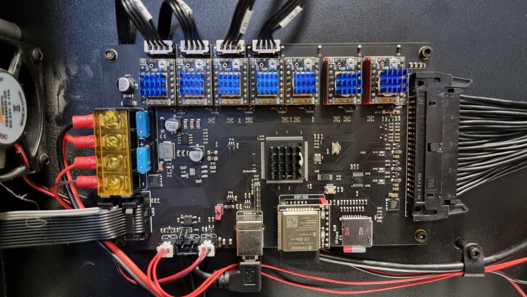
Thanks guys for taking a look. Please see below answers and attached images:
what driver modules do you have installed?
I have Bigtree TMC 2209 v1.2Have you made any changes to the board since it was working:
I Have unplugged everything in the board and then put it all back together checking that there were no issues with wiring on the reverse. 99% sure things went back exactly as they should have?What exactly did "installing a new toolhead" involve:
I installed the new stealth burner and tap upgrade from Formbot. I have updated the the firmware to the relevant team gloomy "tap" firmware.Any clues?
Thanks
David

-
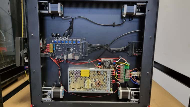
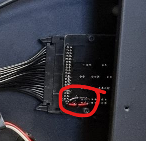
@ThreeDeeDave have you had issues in the past with the breakout board? i've not seen a repair like this before

In terms of the drivers, they seem to be installed fine. Have you removed any of them? Have you changed any of the jumpers before beneath them? -
@jay_s_uk
Break out board: Yes I have, the copper channels on the other side had come loose and detached from the pin somehow. I had a local computer repair shop repair it. This was from before and the issues from this were related to the z homing switch. This all works fine now aside from the current issue of course. It is repaired like this as the copper channel was too damaged to repair with certainty so they suggested connecting from the reverse side.Drivers wise, I took them out when checking the main board for damage. Honestly probably didn't put them back in exactly the same place but I assumed they are all the same so it didn't matter?
Haven't touched the jumpers although I do have loads of spares so could try replacing?
-
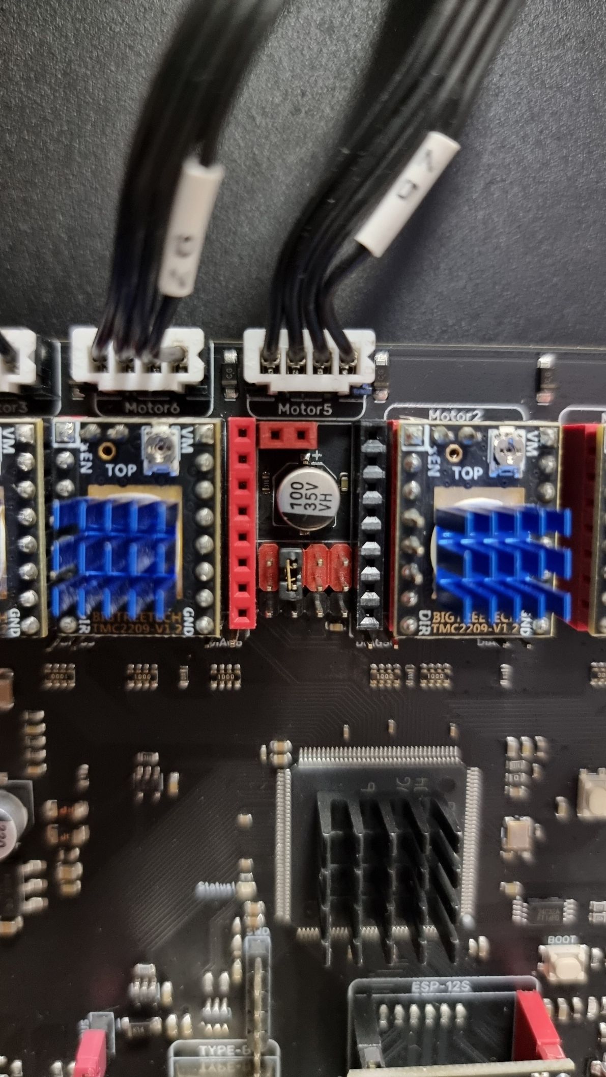
@ThreeDeeDave could you take a photo of one of the slots with the drivers removed? obviously with the power off
-
@jay_s_uk
No problem see below:
-
@ThreeDeeDave thats correct as well which would indicate there may be some sort of hardware issue. I can't see anything wrong with the config etc. best get in contact with Ada at formbot and they should be able to sort you out with a new board. just mention you've spoken to me
-
@jay_s_uk Ok thanks so much for taking the time to look at it, really appreciate it.
Thanks
David