Error: G0/G1: insufficient axes homed
-
@ThreeDeeDave said in Error: G0/G1: insufficient axes homed:
Driver 0: not present
Driver 1: not present
Driver 2: not present
Driver 3: not present
Driver 4: not present
Driver 5: not present
Driver 6: not presentNone of your drivers have been detected, which is not a good start. Run the following command
M122 P200
and the output from that here. You are actually running 3.4.6, not 3.4.5. -
Thanks for taking a look.
Ah ok yes I see that can't be good. Ok please see results:M122 P200
=== Diagnostics ===
RepRapFirmware for STM32F4 based Boards (troodon_v2) version 3.4.6_101 running on STM32F4 at 168Mhz
Bootloader: Unknown== Supported boards ==
Board 0.0: generic iomode 254 Signatures:
Board 1.0: biquskrpro_1.1 iomode 0 Signatures: 0x768a39d6 0x50da391 0xa79a1917
Board 2.0: biqugtr_1.0 iomode 1 Signatures: 0x94a2cc03
Board 3.0: fly_e3_pro iomode 2 Signatures: 0xd0c680ae
Board 4.0: fly_e3_prov3 iomode 2 Signatures: 0xd0c680ae
Board 5.0: fly_f407zg iomode 2 Signatures: 0x8a5f5551 0xd0c680ae
Board 6.0: fly_e3 iomode 2 Signatures: 0xd0c680ae 0xfd2146b0
Board 7.0: fly_e3_v2 iomode 2 Signatures: 0xd0c680ae
Board 8.0: fly_cdyv2 iomode 2 Signatures: 0x8a5f5551 0xd0c680ae
Board 8.1: fly_cdyv3 iomode 2 Signatures: 0x8a5f5551 0xd0c680ae
Board 9.0: fly_super8 iomode 2 Signatures: 0x8a5f5551 0xd0c680ae
Board 10.0: fly_gemini iomode 2 Signatures: 0xbfecc997
Board 11.0: fly_geminiv1.1 iomode 1 Signatures: 0x318f4fbe
Board 12.0: fly_geminiv2.0 iomode 1 Signatures: 0x318f4fbe
Board 13.0: biquskr_rrf_e3_1.1 iomode 2 Signatures: 0x94a2cc03 0xb173b733
Board 14.0: biquskr_2 iomode 2 Signatures: 0xb75b00a7 0x35f4602c
Board 15.0: biqoctopus_1.1 iomode 2 Signatures: 0x5e29d842
Board 15.1: biquoctopus_1.1 iomode 2 Signatures: 0x5e29d842
Board 16.0: biqoctopuspro_1.0 iomode 2 Signatures: 0x5e29d842
Board 16.1: biquoctopuspro_1.0 iomode 2 Signatures: 0x5e29d842
Board 17.0: biquoctopus_x7 iomode 2 Signatures: 0x5e29d842
Board 17.1: troodon_v2 iomode 2 Signatures: 0x5e29d842
Board 18.0: fysetc_spider iomode 1 Signatures: 0x8479e19e
Board 19.0: fysetc_spider_king407 iomode 1 Signatures: 0xb86f16db== Configurable Board.txt Settings ==
board = troodon_v2 Signature 0xe826121bleds.diagnostic = C.7
leds.diagnosticOn = true
leds.activity = NoPin
leds.activityOn = true
pins.SetHigh = {NoPin, NoPin, NoPin, NoPin, NoPin, NoPin, NoPin, NoPin}
pins.SetLow = {NoPin, NoPin, NoPin, NoPin, NoPin, NoPin, NoPin, NoPin}
stepper.powerEnablePin = NoPin
stepper.enablePins = {A.1, C.1, C.5, E.10, E.15, F.12, G.1, NoPin, NoPin, NoPin, NoPin, NoPin, NoPin, NoPin}
stepper.stepPins = {A.3, C.2, B.0, E.11, B.10, F.13, E.7, NoPin, NoPin, NoPin, NoPin, NoPin, NoPin, NoPin}
stepper.directionPins = {A.4, C.3, B.1, E.12, B.11, F.14, E.8, NoPin, NoPin, NoPin, NoPin, NoPin, NoPin, NoPin}
stepper.digipotFactor = 0.00
stepper.TmcUartPins = {A.2, C.0, C.4, E.9, E.14, F.11, G.0, NoPin, NoPin, NoPin, NoPin, NoPin, NoPin, NoPin}
stepper.numSmartDrivers = 7
stepper.num5160Drivers = 0
stepper.spiChannel = 255
stepper.csDelay = 0
stepper.TmcDiagPins = {NoPin, NoPin, NoPin, NoPin, NoPin, NoPin, NoPin, NoPin, NoPin, NoPin, NoPin, NoPin, NoPin, NoPin}
heat.tempSensePins = {A.0, F.3, NoPin, NoPin, NoPin, NoPin, NoPin, NoPin, NoPin}
heat.spiTempSensorCSPins = {NoPin, NoPin, NoPin, NoPin, NoPin, NoPin, NoPin, NoPin}
heat.spiTempSensorChannel = 255
heat.thermistorSeriesResistor = 4700.00
atx.powerPin = NoPin
atx.powerPinInverted = false
atx.initialPowerOn = true
sdCard.internal.spiFrequencyHz = 25000000
sdCard.external.csPin = B.12
sdCard.external.cardDetectPin = D.8
sdCard.external.spiFrequencyHz = 4000000
sdCard.external.spiChannel = 1
lcd.lcdCSPin = G.3
lcd.lcdBeepPin = G.5
lcd.encoderPinA = D.10
lcd.encoderPinB = D.9
lcd.encoderPinSw = G.4
lcd.lcdDCPin = G.2
lcd.panelButtonPin = NoPin
lcd.spiChannel = 1
SPI0.pins = {A.5, A.6, A.7}
SPI1.pins = {B.13, B.14, B.15}
SPI2.pins = {B.3, B.4, B.5}
SPI3.pins = {NoPin, NoPin, NoPin}
SPI4.pins = {NoPin, NoPin, NoPin}
SPI5.pins = {NoPin, NoPin, NoPin}
8266wifi.espDataReadyPin = D.0
8266wifi.lpcTfrReadyPin = D.3
8266wifi.TfrReadyPin = D.3
8266wifi.espResetPin = G.14
8266wifi.csPin = A.15
8266wifi.serialRxTxPins = {D.6, D.5}
8266wifi.spiChannel = 2
8266wifi.clockReg = 0
serial.aux.rxTxPins = {NoPin, NoPin}
led.neopixelPin = D.14
power.VInDetectPin = NoPin
power.voltage = 24
accelerometer.spiChannel = 255== Defined Pins ==
e0temp,th0 = F.3
bedtemp,tb = A.0
xstop = F.2
ystop = C.15
zstop = C.13
e0stop,e0det = C.14
probe,PS1 = F.4
pro_sw,PS = G.7
bed = D.12
e0heat = B.9
fan0,fan = B.8
fan1 = B.7
fan2 = E.5
fan3 = C.6
fan4 = E.6
BEEP = G.5
BTNENC = G.4
LCDEN = G.3
LCDRS = G.2
LCDD4 = D.15
LCDD5 = D.14
LCDD6 = D.13
LCDD7 = D.11
LCDMISO = B.14
LCDSCK = B.13
BTNEN1 = D.10
LCDSS = B.12
BTNEN2 = D.9
LCDMOSI = B.15
LCDCD = D.8
LED,status = C.7
diag4 = E.13
diag5 = F.9
diag6 = F.15
SCL1 = F.1
SDA1 = F.0== Hardware Serial ==
AUX Serial: Disabled
WIFI Serial: UART 2== PWM ==
0: Pin D.12 freq 0 value 0.000000
1: Pin B.9 freq 0 value 0.000000
2: Pin B.7 freq 0 value 0.000000
3: Pin B.8 freq 0 value 0.000000
4: Pin E.5 freq 0 value 0.000000
5: Pin C.6 freq 0 value 0.000000
6: Pin E.6 freq 0 value 0.000000
7: Pin D.15 freq 0 value 1.000000
8: Pin G.5 freq 0 value 0.000000
9:
10:
11:
12:
13:
14:
15:== Attached interrupt pins ==
0: D.0
1:
2:
3:
4:
5:
6:
7:
8:
9:
10:
11:
12:
13:
14:
15: A.15== MCU ==
AdcBits = 14
TS_CAL1 (30C) = 926
TS_CAL2 (110C) = 1207
V_REFINCAL (30C 3.3V) = 1495V_REFINT raw 6083
V_REF 3.245724T_MCU raw 3890
T_MCU cal 43.238434
T_MCU calc 34.422447T_MCU raw (corrected) 3826
T_MCU cal (corrected) 38.684681
T_MCU calc (corrected) 29.267479
Device Id 413 Revison Id 100f CPUId r0p1== RAM ==
RAM start 0x20000000 end 0x2001fffc
CCMRAM start 0x10000000 end 0x1000fffc== USB ==
Read overrun 0 -
@ThreeDeeDave I don't see any obvious problem, what driver modules do you have installed? Have you made any changes to the board since it was working? What exactly did "installing a new toolhead" involve? I'm not really very familiar with that board/printer but I think @jay_s_uk Had one for a while so he may have some ideas.
-
@ThreeDeeDave i can't see anything wrong with what's being reported there either.
Best thing is detail what you've changed, include some photos of the underside of the machine or even better, join us on discord https://discord.gg/uS97Qs7 -
You really don't need to make your homing code that complicated.
I've been using very simple code for years on multiple printers and never had an issue with just the basic:
; assumes endtop is at axis high end
G1 H1 Xaaa Fddd
G1 X-bbb
G1 H1 Xccc Feee
You don't need to do the test to see if the endstop is already triggered at the start. If the endstop is triggered that just means the fast G1 H1 is, in essence, already done.
--
As to your issue - I don't see anything except for the driver report but you are using hardware that I have no experience with.
Frederick
Printers: a E3D MS/TC setup and a RatRig Hybrid. Using Duet 3 hardware running 3.4.6
-
@fcwilt thats the homing file we provide https://github.com/TeamGloomy/Troodon-V2/blob/improved/Config/sys/homex.g
Owns various duet boards and is the main wiki maintainer for the Teamgloomy LPC/STM32 port of RRF. Assume I'm running whatever the latest beta/stable build is
-
@fcwilt said in Error: G0/G1: insufficient axes homed:
You don't need to do the test to see if the endstop is already triggered at the start. If the endstop is triggered that just means the fast G1 H1 is, in essence, already done.
It could also mean that a wire has become detached from the end stop or the switch itself is faulty. In which case, the axis will be homed even though the print head is some distance away from the switch position. Say for example on the first pass, the head was X = 50mm away from the switch but the wire had fallen off, when you home the machine it will set X=50 as X=0 so then when you travel to X max, the head will collide with the frame some 50mm before X max. So check if the switch is triggered - if so move a short distance away and check again. If it's still triggered something is amiss so flag this and abort is the best approach IMO.
-
Yes it certainly is protection against that sort of failure but given the multiplicity of things that can fail it's protection against just one.

Frederick
Printers: a E3D MS/TC setup and a RatRig Hybrid. Using Duet 3 hardware running 3.4.6
-
-
@fcwilt said in Error: G0/G1: insufficient axes homed:
Yes it certainly is protection against that sort of failure but given the multiplicity of things that can fail it's protection against just one.
Frederick
Sure. But if you've ever slammed a couple of kgs of print head against a frame, you'll know that protection is worth having - especially as it costs nothing and takes milliseconds to check.

-
Thanks guys for taking a look. Please see below answers and attached images:
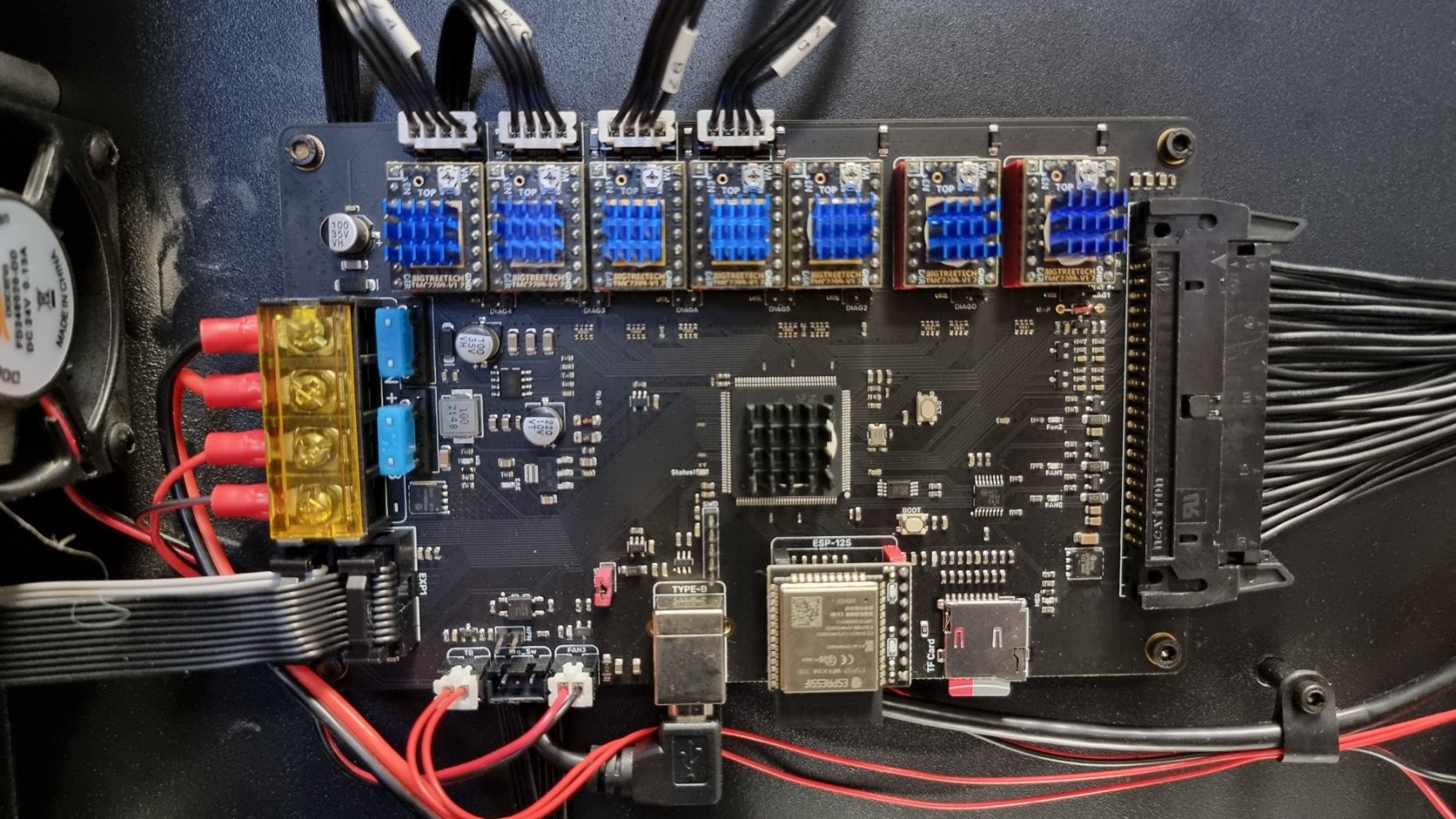
what driver modules do you have installed?
I have Bigtree TMC 2209 v1.2Have you made any changes to the board since it was working:
I Have unplugged everything in the board and then put it all back together checking that there were no issues with wiring on the reverse. 99% sure things went back exactly as they should have?What exactly did "installing a new toolhead" involve:
I installed the new stealth burner and tap upgrade from Formbot. I have updated the the firmware to the relevant team gloomy "tap" firmware.Any clues?
Thanks
David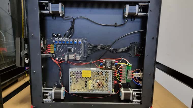
-
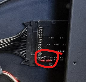
@ThreeDeeDave have you had issues in the past with the breakout board? i've not seen a repair like this before
In terms of the drivers, they seem to be installed fine. Have you removed any of them? Have you changed any of the jumpers before beneath them? -
@jay_s_uk
Break out board: Yes I have, the copper channels on the other side had come loose and detached from the pin somehow. I had a local computer repair shop repair it. This was from before and the issues from this were related to the z homing switch. This all works fine now aside from the current issue of course. It is repaired like this as the copper channel was too damaged to repair with certainty so they suggested connecting from the reverse side.Drivers wise, I took them out when checking the main board for damage. Honestly probably didn't put them back in exactly the same place but I assumed they are all the same so it didn't matter?
Haven't touched the jumpers although I do have loads of spares so could try replacing?
-
@ThreeDeeDave could you take a photo of one of the slots with the drivers removed? obviously with the power off
-
@jay_s_uk
No problem see below: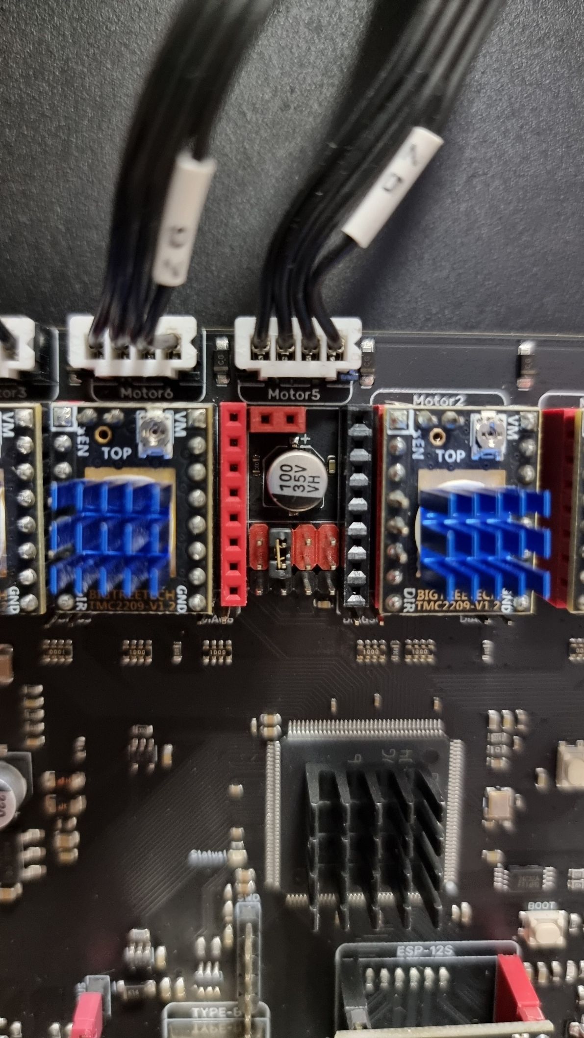
-
@ThreeDeeDave thats correct as well which would indicate there may be some sort of hardware issue. I can't see anything wrong with the config etc. best get in contact with Ada at formbot and they should be able to sort you out with a new board. just mention you've spoken to me
-
@jay_s_uk Ok thanks so much for taking the time to look at it, really appreciate it.
Thanks
David