Help with seam spots tuning
-
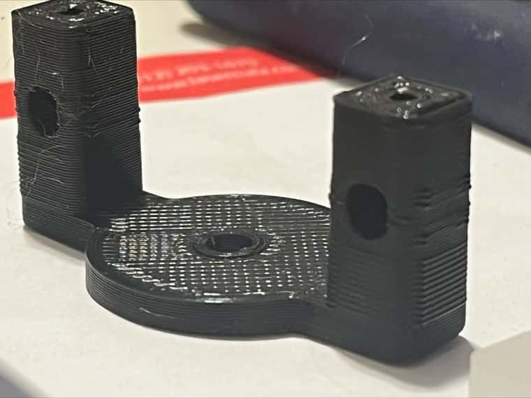
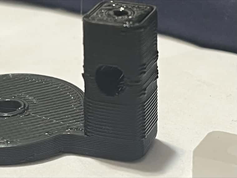
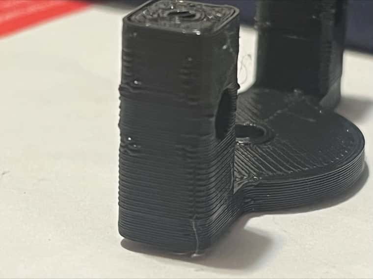
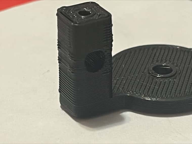
im going bit crazy trying to figure out how to remove seam spot, i tried all setting include slicer options to hide seam but that does not work. i tried all retraction height, z hoping, accelerations, temperatures, coasting, checked estops and so far no luck while my maker bot prints part just fine
a bit wade question but any one had same problems? or how can i troubleshoot?
attached photos and cura project along with config.; Configuration file for Duet WiFi (firmware version 3). ; executed by the firmware on start-up ; ; generated by RepRapFirmware Configuration Tool v3.2.3 on Tue Jun 08 2021 21:52:22 GMT-0400 (Eastern Daylight Time) ; General preferences G90 ; send absolute coordinates... M83 ; ...but relative extruder moves M550 P"Duet2Wifi" ; set printer name ; Network M552 S1 ; enable network M586 P0 S1 ; enable HTTP M586 P1 S0 ; disable FTP M586 P2 S0 ; disable Telnet ; Drives M569 P0 S1 ; physical drive 0 goes forwards X M569 P1 S1 ; physical drive 1 goes forwards Y ;M569 P2 S1 ; physical drive 2 goes forwards Z edited M569 P3 S1 ; physical drive 3 goes forwards ;Triple Z Drive Direction M569 P5 S0 M569 P6 S0 M569 P7 S0 ;M569 P8 S0 M584 X0 Y1 Z5:6:7 E3 ; set drive mapping (Alexus backup: X0 Y1 Z2 E3) ==> X0 Y1 Z10 E3 ==> adding 4 z motors 10.8.23 M350 X16 Y16 Z16 E16 I1 ; configure microstepping with interpolation M92 X80.00 Y44.44 Z1280 E800 ; set steps per mm (Alexus 6.28.21 - fine tuned alredy - do not edit)Z320 -> Z1280 M566 X900.00 Y900.00 Z80.00 E3000.00 ; set maximum instantaneous speed changes (mm/min) (jerk) M203 X3000.00 Y3000.00 Z200.00 E15000.00 ; set maximum speeds (mm/min) M204 P1000 T3000 ; Set printing and travel accelerations M201 X3000.00 Y3000.00 Z200.00 E8000.00 ; set accelerations (mm/s^2) M906 X800 Y1200 Z1000 E800 I30 ; set motor currents (mA) and motor idle factor in per cent M84 S15 ; Set idle timeout ; Acceleration Calculator ; https://wilriker.github.io/maximum-acceleration-calculator/ ; Axis Limits M208 X0 Y0 Z0 S1 ; set axis minima M208 X500 Y470 Z600 S0 ; set axis maxima ;Lead Screw Locations (Alexus, 3Z Motor Setup) M671 X600:600:-85 Y345:68:209 S7 ; position of leadscrew/bed pivot point at 5,6,7 Motors (in that oreder), Includes adlustments as screws are outside the bed. S- how much adjusmpents permited mechanically ; Endstops M574 X1 S1 P"!xstop" ; configure active-high endstop for low end on X via pin xstop M574 Y1 S1 P"!ystop" ; configure active-high endstop for low end on Y via pin ystop M574 Z1 S1 P"!zstop" ; configure active-high endstop for low end on Z via pin zstop ;M574 Z1 S2 ; Config to use Prbe as Z Limit (Alexus) ; Z-Probe ;Alexus BL Touch Declarations M558 P9 C"^zprobe.in" H5 F100 T2000 ; Type 9 BL Touc, w/ pull up, H5 is dive heght 5mm M950 S0 C"duex.pwm1" ; Duex5 PWM port - pin 8 yellow wire for servo deploy PWM G31 X28.78 Y0 Z1.7429 P25 ; Probe Offest (old z 3.02) ; END declarations M557 X50:500 Y0:500 S75 ; define mesh grid ; Heaters M140 H-1 ; disable heated bed (overrides default heater mapping) M308 S0 P"e0temp" Y"thermistor" T100000 B4138 ; configure sensor 0 as thermistor on pin e0temp M950 H0 C"e0heat" T0 ; create nozzle heater output on e0heat and map it to sensor 0 M307 H0 B0 S1.00 ; disable bang-bang mode for heater and set PWM limit M143 H0 S280 ; set temperature limit for heater 0 to 280C ; Fans M950 F0 C"fan0" Q500 ; create fan 0 on pin fan0 and set its frequency M106 P0 S0 H-1 ; set fan 0 value. Thermostatic control is turned off M950 F1 C"fan1" Q500 ; create fan 1 on pin fan1 and set its frequency M106 P1 S0.8 H0 ; set fan 1 value. Thermostatic control is turned ON for sensor 0 (S0 in M308) H0 ; Tools M563 P0 D0 H0 F0 ; define tool 0 (asign F0 as part cooking fan.. used to be F-1) G10 P0 X0 Y0 Z0 ; set tool 0 axis offsets G10 P0 R0 S0 ; set initial tool 0 active and standby temperatures to 0C ; Custom settings are not defined ; Miscellaneous M575 P1 S1 B57600 ; enable support for PanelDue M501 ; load saved parameters from non-volatile memory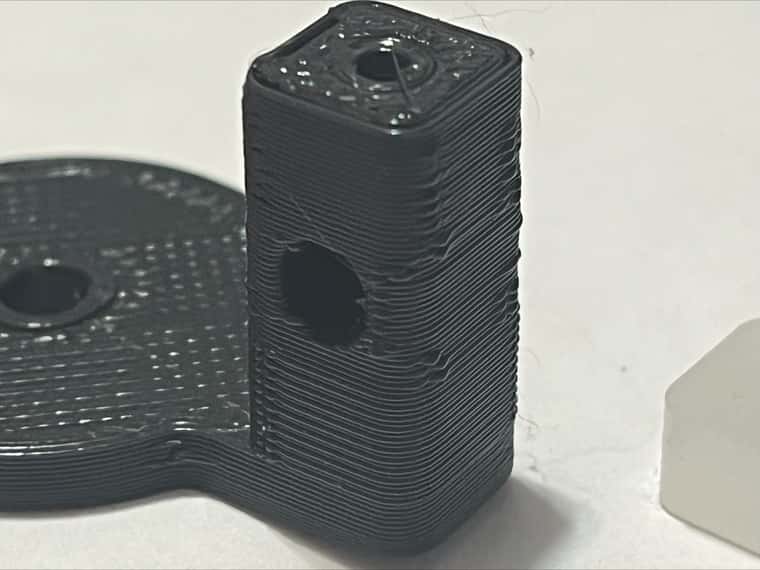
-
Seems very much like over-extrusion .....
Have you verified that the extruder is extruding the right amount of filament?
What is your extrusion multiplier? -
@jens55
extruder feeds exactly what requested ex i ask for 100mm of filament and 100mm exactly go in
multiplier is 100%
in infill i was not getting enough material so as should be seen in cura file i set flow like 150 otherwice i get spider web and not infill at that speed... i can try to reduce flow for outer walls but semas only problem is at the end spot that's why i even tried coasting (or maybe its begining... hard to tell) will try reducing flow -
@alexus Is the object the correct dimensions, specifically in the Z axis?
Ian
Bed-slinger - Mini5+ WiFi/1LC | RRP Fisher v1 - D2 WiFi | Polargraph - D2 WiFi | TronXY X5S - 6HC/Roto | CNC router - 6HC | Tractus3D T1250 - D2 Eth
-
@droftarts
reasonably yes
file is 23.5mm measured size 23.1 - 23.4mm possibly due to warping also caliper tolerance -
@alexus What about filament width? While it's extruding the correct distance, if the filament width isn't set correctly, it can easily over extrude. Perhaps try one of the thin wall tests to see how much filament is extruding.
Ian
Bed-slinger - Mini5+ WiFi/1LC | RRP Fisher v1 - D2 WiFi | Polargraph - D2 WiFi | TronXY X5S - 6HC/Roto | CNC router - 6HC | Tractus3D T1250 - D2 Eth
-
@droftarts
filament is 1.6mm (advertised as 1.75mm)
how do i do thin wall test? -
@alexus I’ve recently used this one: https://guides.bear-lab.com/Guide/Extrusion+multiplier+and+filament+diameter/8?lang=en
Ian
Bed-slinger - Mini5+ WiFi/1LC | RRP Fisher v1 - D2 WiFi | Polargraph - D2 WiFi | TronXY X5S - 6HC/Roto | CNC router - 6HC | Tractus3D T1250 - D2 Eth
-
@droftarts
need to get micrometer and try it -
@alexus Digital calipers are fine.
Ian
Bed-slinger - Mini5+ WiFi/1LC | RRP Fisher v1 - D2 WiFi | Polargraph - D2 WiFi | TronXY X5S - 6HC/Roto | CNC router - 6HC | Tractus3D T1250 - D2 Eth
-
@droftarts
in thta case i can use my cheap china caliper lol i dont think its well relibale -
@alexus
so did thin wall test and looks like my walls are 0.4mm on 0.4mm nozle seams good to me
though i switched to prusa slicer for that test and i printed 2 models
one (other design) got printed defets free , perfect part , while same part foprm cura never been perfect... then i printed my part with 2 prone towers and while it printed significantly better it still showed similar artifact perhaps tuning prisa slicer can make it better... failr note i did change material and i put material in drying/preheat chamber -
You might be interested in a method that I developed to make seams just about invisible. I have documented it in a feature request for PrusaSlicer here: scarf seam
The method requires the outside perimeter to be printed first. The layer starts at zero layer height (i.e. the nozzle is at the same z-height as it was for the previous layer), then tapers upwards to the full layer height over some arbitrary distance, and then at the end of the layer there is a complementary taper over the first few points before the nozzle moves away to complete the layer in the normal manner. The result is analogous to a woodworker's scarf joint and so I'm calling it a scarf seam.
The results are quite impressive, as you can see at the linked page, and with my hand-written gcode it is easy to achieve. The whole process can be done by a slicer but, in my opinion, the tapers should be processed by the firmware. I asked about adding moves that taper in Z for ReRap firmware some time ago, but I'm not sure that I had this particular use-case worked out at the time. https://forum.duet3d.com/topic/32474/tapering-extrusions I guess it might be worth re-visiting that request.
-
@MJLew
i can try ur gcode just to see how it print , but as i see features are not added any wehere so far?
also what i noticed with my models, cylindrical is ok when i used prusa slicer but 2 tower with hole in it still seams terrible