Configs for PCB PnP for Duet3D 6XD and 3 x 3HC expansion boards
-
@dc42
In trying to troubleshoot the homing Failure for X and Y axis, I noticed that when NEMA 34 Closed Loop Motors ( 86HSE8N-BC38 8.0N.m ) with External Driver (HSS86) are energized(48V Power is applied ) it locks, as it should, but does not move when i try to home it even after changes . Without Power applied i can move it manually and moves fine as expectedi have double checked all Wiring from Motor <---> Driver <--> Duet 3 6XD and seems correct as expected, No error light on the Driver or Duet 6XD
-
I am thinking that one of Motor Power (A+, A-, B+, B-) internal wires might be crossed or swapped or
-
PSU Output supply 48V DC @ 12.5A Max . is this an undervoltage issue ?
Looking at the Datasheets of both the Driver and Closed Loop Motor, it seems to suggest that the recommended DC is 60V while some documents say 48V . i am perplexed on this. Any one with an idea about this motors or drivers?
-
-
@developeralgo222 have you ever got the X and Y axes moving? I notice you haven’t got a T parameter in your M569 command for X and Y:
M569 P0.0 S1 R1 ; X-Axis physical drive 0.0 goes forwards on CAN ID = 0 - Duet 6XD Drive 0.0 M569 P0.1 S1 R1 ; Y-Axis physical drive 0.1 goes forwards on CAN ID = 0 - Duet 6XD Drive 0.1 T controls the timing of the step pulses:
Taa:bb:cc:dd (firmware 1.21 and later) Minimum driver step pulse width, step pulse interval, direction setup time and direction hold time, in microseconds
I haven’t ploughed through the drive manual, but try T5:5:10:10 eg
M569 P0.0 S1 R1 T5:5:10:10Ian
-
@developeralgo222 the motor voltage is unlikely to be critical. Higher voltage allows movement at higher speeds before torque drops off.
Please provide a link to the datasheet of the motor driver, and show us how you have connected it to the 6XD.
-
@dc42
Here are the links to the Datasheets-
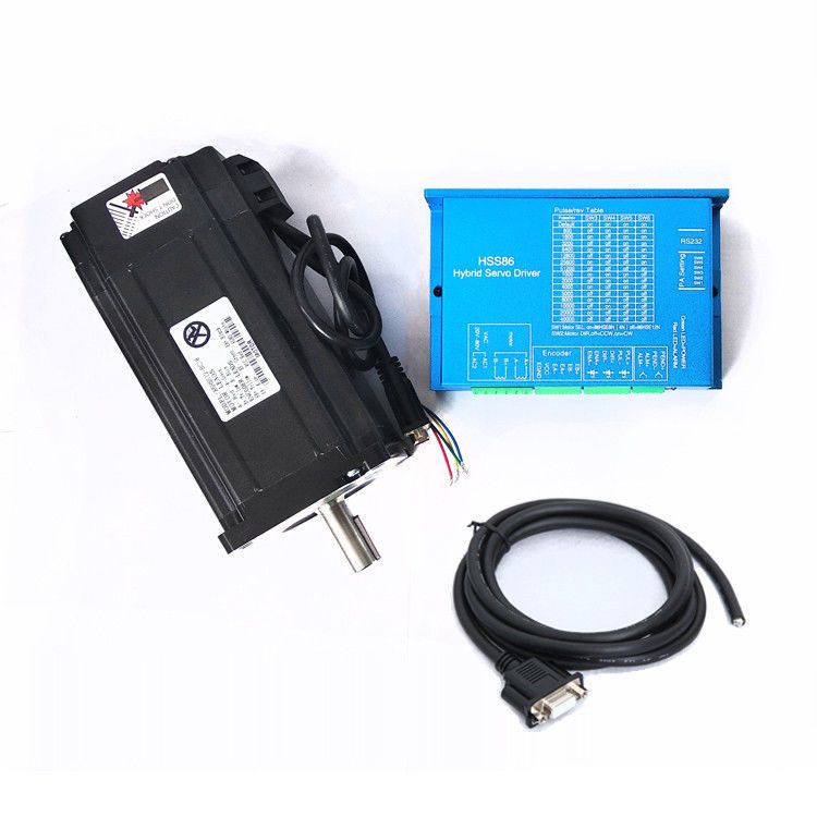
Driver: HSS86 Closed Look Driver HSS86
-
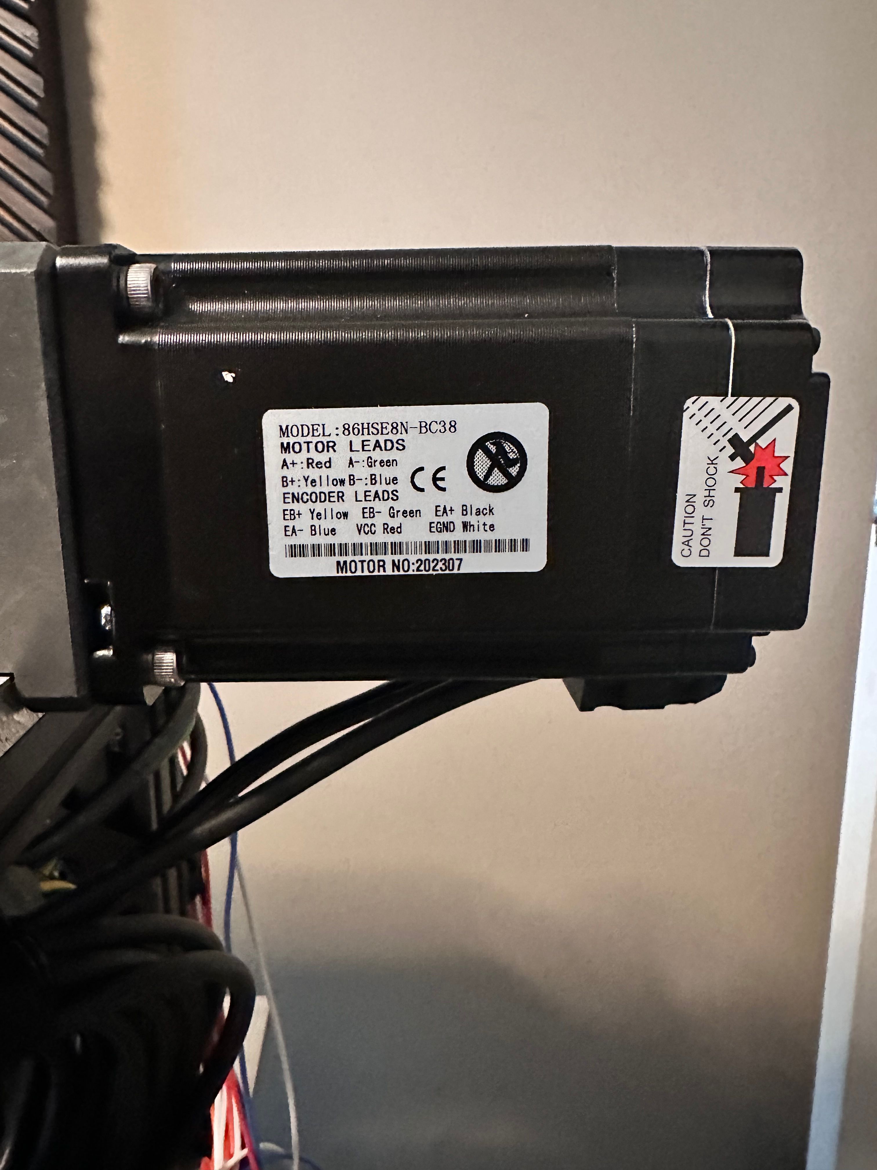
Nema 34 8 N.m Closed Loop Motor
86HSE8N-BC38 or this link 86HSE8N-BC38
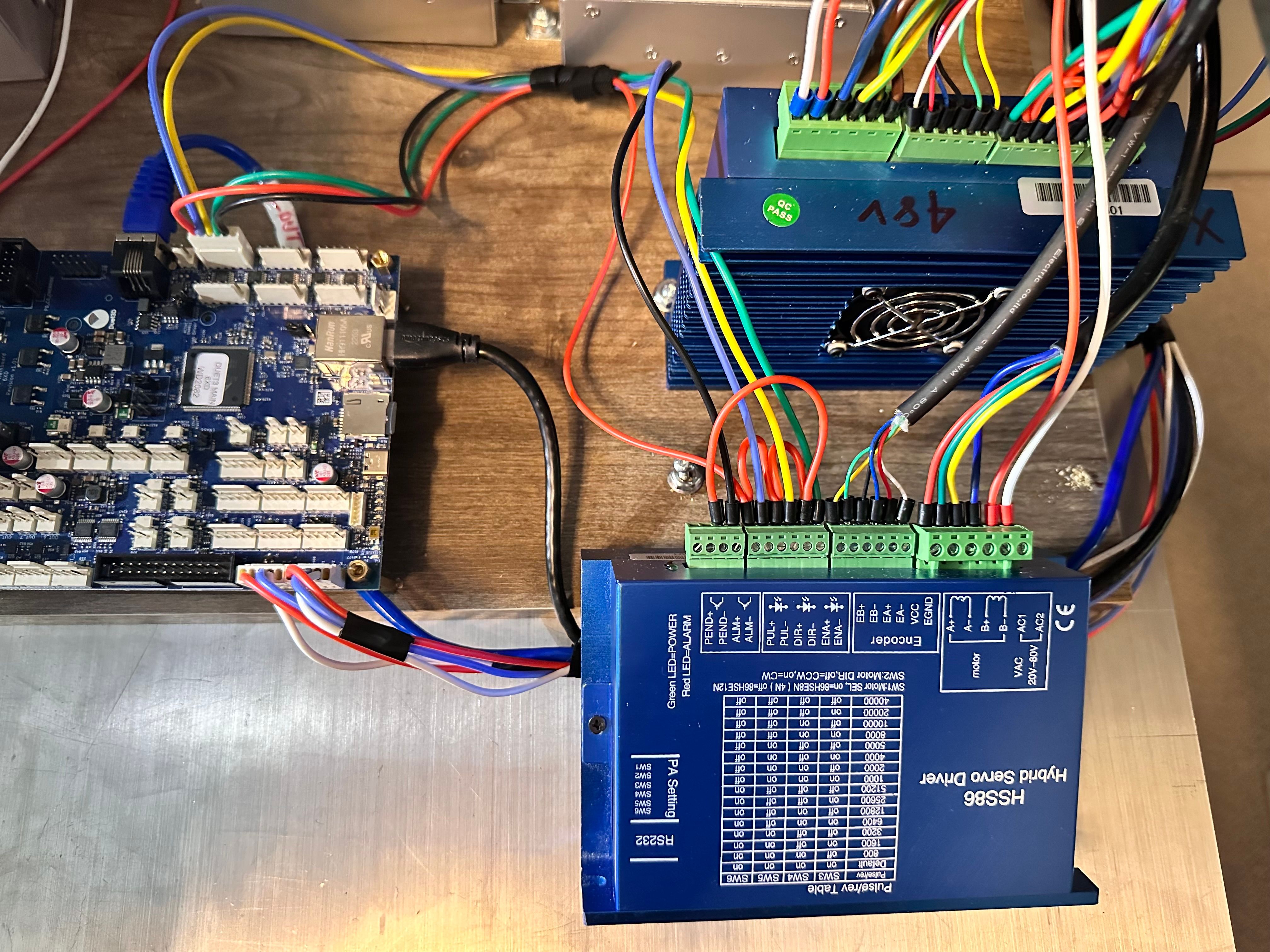
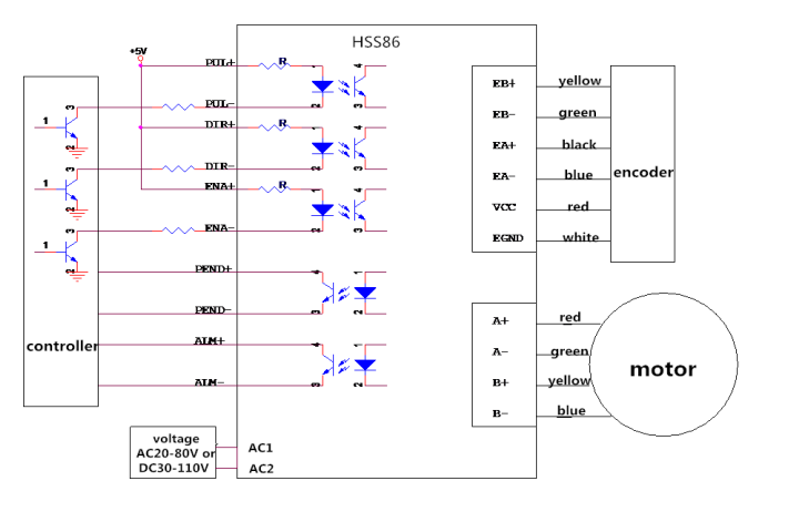
As per the Datasheet wiring
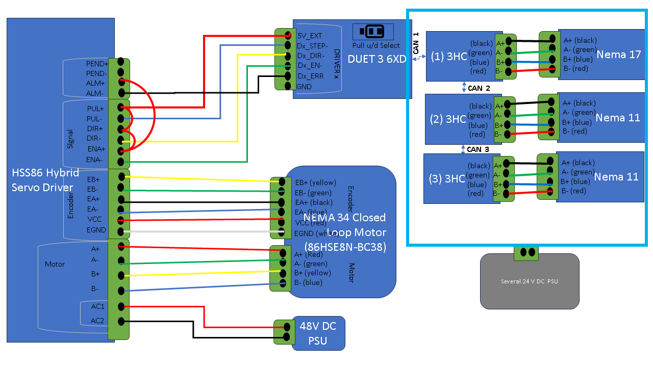
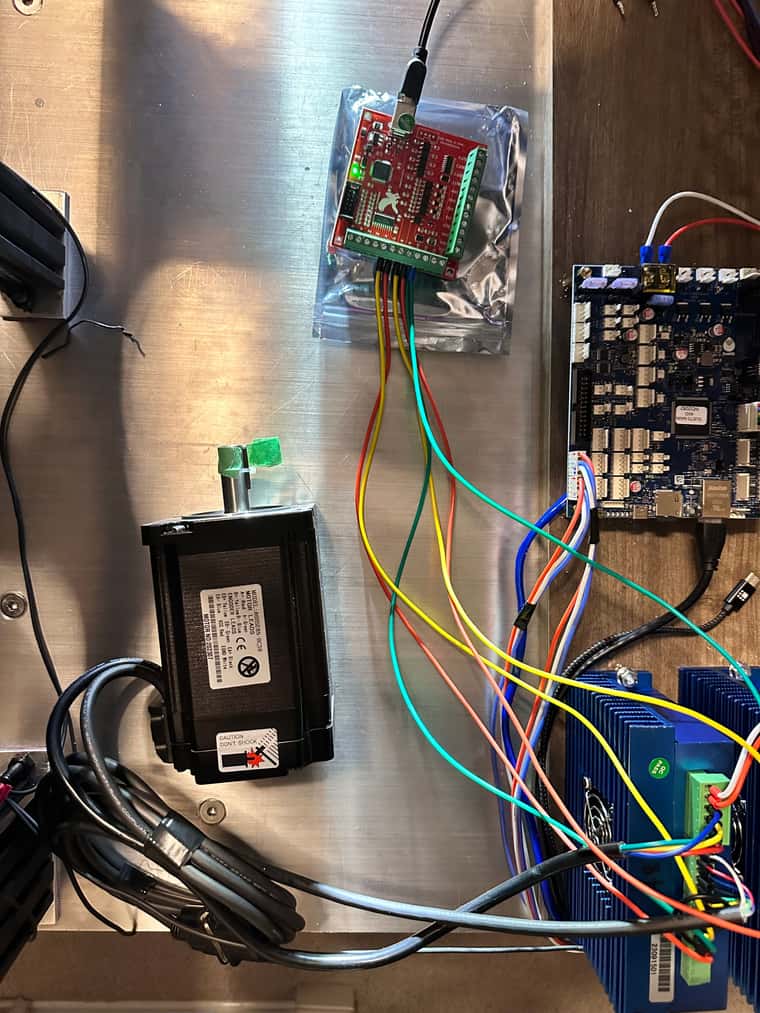
My Actual wiring of NEMA 34 Closed Loop(86HSE8N-BC38) + HSS86 Hybrid Servo Driver + Duet 3 6XD as per the datasheets
-
-
@droftarts said in Configs for PCB PnP for Duet3D 6XD and 3 x 3HC expansion boards:
M569 P0.0 S1 R1 T5:5:10:10
I have not got X and Y to move, The Motor is energized fine, no errors on the driver but they don't move. No meaningful error on the Duet Web Control console. i have updated config.g and other files as per suggestions here from users but to no avail.
-
@developeralgo222 I know several people are trying to help you (and I'll try to where I can as well), but can you do the following?
- Post your latest config.g file
- In the console type M98 P"config.g", and post what the results are.
- Can you please verify if you have tested X and Y motor movement like dc42 has described below---
dc42 said in Configs for PCB PnP for Duet3D 6XD and 3 x 3HC expansion boards:
- Test motor movement like this:
- Send G91 to put the machine into relative movement mode
- Use G1 H2 commands to command individual motors regardless of their homed status. For example, G1 H2 X10 should move the X axis by +10mm, and G1 H2 X-10 should move it by -10mm.
- Read the endstop states, either by using M119, or in Duet Web Control start the Object Model Browser and expand sensors/endstops. Check that the state changes as expected when you operate the endstop.
--- and let us know what happens (nothing? error light on the HSS86 driver?)
4. What do you have the microstep settings set to on the driver (with the SW3、SW4、SW5、SW6 switches)While we are trying to help you 'piece by piece', it is very helpful for us if you respond by answering all the questions previously asked - it helps us work out what could be going wrong. In addition, posting your updated config.g once you make changes is extremely important, as it helps us 'peer review' the changes that have been made. If we can't see the config.g file, we won't be 100% sure with whats going on.
-
@sebkritikel said in Configs for PCB PnP for Duet3D 6XD and 3 x 3HC expansion boards:
M98 P"config.g"
Config.g
; Configuration file for Duet 3 MB 6XD (firmware version 3.3) ; executed by the firmware on start-up ; ; generated by RepRapFirmware Configuration Tool v3.3.16 on Tue Dec 05 2023 09:51:46 GMT-0500 (Eastern Standard Time) ; General preferences G90 ; send absolute coordinates... M83 ; ...but relative extruder moves M550 P"MYTEST PNP" ; set printer name ; Wait a moment for the CAN expansion boards to start G4 S2 ; Network if {network.interfaces[0].type = "ethernet"} M552 P10.0.0.200 S1 ; enable network and set IP address M553 P255.255.255.0 ; set netmask M554 P10.0.0.1 ; set gateway else M552 S1 M586 P0 S1 ; enable HTTP M586 P1 S0 ; disable FTP M586 P2 S0 ; disable Telnet ;The X axis to control the movement of the PnP head right and left. Right(Clockwise rotation to move Forward = S0) is positive. ;The Y axis to control the movement of the PnP head forward and back. Forward( AntiClockwise rotation to move Forward = S1) is positive. ;The Z axis to control raising and lowering of the PnP nozzle up and down. Up is positive. ;The V, U, W, A, B, C (for 6-Head nozzles) axes rotates clockwise and counter-clockwise. Counter-clockwise is positive. ;RepRapFirmware supports X, Y and Z axes as standard and allows you to create up to 7 additional axes depending on the firmware ;version and which Duet you are using. Axes are created and associated with ;stepper motors using the M584 command in config.g. ;You may use any of the following letters to refer to the new axes: U V W A B C D (letter D is not supported in older firmware versions) ;If no T parameter is given, then on boards having internal drivers the step pulse width and interval are guaranteed to be suitable for the on-board drivers only, ;and will generally be too fast for external drivers. On the MB6XD board the default is T2.5:2.5:2.5:2.5. ; Drives ;Physical Drives CAN ID = 0 M569 P0.0 S0 R1 T5:5:10:10 ; X-Axis physical drive 0.0 goes forwards on CAN ID = 0 - Duet 6XD Drive 0.0 with 5us timings between pulses M569 P0.1 S1 R1 T5:5:10:10 ; Y-Axis physical drive 0.1 goes forwards on CAN ID = 0 - Duet 6XD Drive 0.1 with 5us timings between pulses ;Physical Drives CAN ID = 1 M569 P1.0 S1 ; Z & U Axis physical drive 1.0 Rotates Clockwise or Anticlockwise to move CAM driven dual nozzles down and up on Z & U axis on CAN ID = 1 - Duet 3HC Drive 1.0 M569 P1.1 S1 ; V & W Axis physical drive 1.1 Rotates Clockwise or Anticlockwise to move CAM driven dual nozzles down and up on V & W axis on CAN ID = 1 - Duet 3HC Drive 1.1 M569 P1.2 S1 ; A & B Axis physical drive 1.2 Rotates Clockwise or Anticlockwise to move CAM driven dual nozzles down and up on A & B axis on CAN ID = 1 - Duet 3HC Drive 1.2 ;Physical Drives CAN ID = 2 M569 P2.0 S1 ; C-Axis physical drive 2.0 goes Rotates forwards and backwards (+180 and -180 ) on CAN ID = 2 - Duet 3HC Drive 2.0 M569 P2.1 S1 ; D-Axis physical drive 2.1 goes Rotates forwards and backwards (+180 and -180 ) on CAN ID = 2 - Duet 3HC Drive 2.1 M569 P2.2 S1 ; 'A-Axis physical drive 2.2 goes Rotates forwards and backwards (+180 and -180 ) on CAN ID = 2 - Duet 3HC Drive 2.2 ;Physical Drives CAN ID = 3 M569 P3.0 S1 ; 'B-Axis physical drive 3.0 goes Rotates forwards and backwards (+180 and -180 ) on CAN ID = 3 - Duet 3HC Drive 3.0 M569 P3.1 S1 ; 'C-Axis physical drive 3.1 goes Rotates forwards and backwards (+180 and -180 ) on CAN ID = 3 - Duet 3HC Drive 3.1 M569 P3.2 S1 ; 'D-Axis physical drive 3.2 goes Rotates forwards and backwards (+180 and -180 ) on CAN ID = 3 - Duet 3HC Drive 3.2 ;By default Z U V W are linear and A B C D are rotary; but you can change that using the R ; set visible drive mapping ; X-Axis , Y-Axis (2 x Nema 34 Closed Loop Motors) and Z-Axes (Z,U,V,W,A,B) mapping to 3 Stepper motors ; directly connected to 3HC (CAN ID = 1) (which moves the nozzles up and down along Z-axis) ;M584 X0.0 Y0.1 Z1.0 U1.0 V1.1 W1.1 A1.2 B1.2 R0 ; LIN R0 = LINEAR, R1 = ROTATION M584 X0.0 Y0.1 R0 ; LIN R0 = LINEAR, R1 = ROTATION ; Rotational Axes mapping (C, D, 'A, 'B, 'C, 'D ) to 6 motors directly connected to 3HC (CAN ID 2 and 3) (which rotates the nozzles +180 / -180 along Rotational axis) ;M584 C2.0 D2.1 'A2.2 'B3.0 'C3.1 'D3.2 R1 ; LIN R0 = LINEAR, R1 = ROTATION M584 Z1.0 U1.0 V1.1 W1.1 A1.2 B1.2 C2.0 D2.1 'A2.2 'B3.0 'C3.1 'D3.2 R1 ; LIN R0 = LINEAR, R1 = ROTATION M350 X16 Y16 Z16 U16 V16 W16 A16 B16 C16 D16 'A16 'B16 'C16 'D16 I1 ; configure microstepping with interpolation M92 X40.00 Y40.00 Z8.888 U8.888 V8.888 W8.888 A8.888 B8.888 C8.888 D8.888 'A8.888 'B8.888 'C8.888 'D8.888 ; set steps per mm 50mm/rev M566 X900.0 Y900.0 Z900.0 U900.0 V900.0 W900.0 A900.0 B900.0 C100.0 D100.0 'A100.0 'B100.0 'C100.0 'D100.0 ; set maximum instantaneous speed changes (mm/min) M203 X126000.00 Y126000.00 Z24000.00 U24000.00 V24000.00 W24000.00 A24000.00 B24000.00 C24000.00 D24000.00 'A24000.00 'B24000.00 'C24000.00 'D24000.00 ; set maximum speeds (mm/min) M201 X50000.00 Y50000.00 Z500.00 U500.00 V500.00 W500.00 A500.00 B500.00 C5000.00 D5000.00 'A5000.00 'B5000.00 'C5000.00 'D5000.00 ; set accelerations (mm/s^2) M906 X800 Y800 Z600.0 U600.0 V600.0 W600.0 A600.0 B600.0 C500.0 D500.0 'A500.0 'B500.0 'C500.0 'D500.0 I30 ; set motor currents (mA) and motor idle factor in per cent M84 S30 ; Set idle timeout M564 H0 ; Sets homing, H0 allows mvmnt wo homing ; Axis Limits M208 X0 Y0 Z-160 U-160 V-160 W-160 A-160 B-160 C0 D0 'A0 'B0 'C0 'D0 S1 ; Set axis minima M208 X500 Y500 Z0 U0 V0 W0 A0 B0 C180 D180 'A180 'B180 'C180 'D180 S0 ; Set axis maxima ; There are two parameters to be set for each endstop: ; (1) The electrical type of the endstop (S parameter). S0 = active low (S0, e.g. normally-open switch or Hall sensor), S1 = active high (S1, e.g. a normally-closed switch or opto switch), ; S2 = Use Z probe (S2) and S3 = for using motor stall detection (S3). ; (2) Whether the endstop is at the minimum end (Low End) or the maximum end (High End) of the axis. ; These are the X, Y and Z parameters. 0 = no endstop present(e.g X0) , 1 = an endstop switch at the Minimum end (e.g X1) , 2 = an endstop switch at the Maximum end (e.g X2) of the axis. ; Endstops ; For X and Y Axis M574 X2 S1 P"!io0.in" ; configure switch-type (e.g. microswitch) endstop for low end on X via pin io0.in M574 Y2 S1 P"!io1.in" ; configure switch-type (e.g. microswitch) endstop for low end on Y via pin io1.in ; For Z-Axis (Z,U,V,W,A,B) - Up/down) -- CAM Driven Dual Nozzles ( 1 Motor rotates up/down to drive 2 Nozzles ) M574 Z1 S1 P"!1.io0.in" ; configure switch-type (e.g. microswitch) endstop for low end on Z via pin 1.io0.in M574 U1 S1 P"!1.io1.in" ; configure switch-type (e.g. microswitch) endstop for low end on U via pin 1.io1.in M574 V1 S1 P"!1.io2.in" ; configure switch-type (e.g. microswitch) endstop for low end on V via pin 1.io2.in M574 W1 S1 P"!1.io3.in" ; configure switch-type (e.g. microswitch) endstop for low end on W via pin 1.io3.in M574 A1 S1 P"!1.io4.in" ; configure switch-type (e.g. microswitch) endstop for low end on A via pin 1.io4.in M574 B1 S1 P"!1.io5.in" ; configure switch-type (e.g. microswitch) endstop for low end on B via pin 1.io5.in ; For Rotational Axes only (C,D,'A,'B,'C,'D) +180 / - 180 ) M574 C1 S1 P"!2.io0.in" ; configure switch-type (e.g. microswitch) endstop for low end on C via pin 2.io0.in M574 D1 S1 P"!2.io1.in" ; configure switch-type (e.g. microswitch) endstop for low end on D via pin 2.io1.in M574 'A1 S1 P"!2.io2.in" ; configure switch-type (e.g. microswitch) endstop for low end on 'A via pin 2.io2.in M574 'B1 S1 P"!3.io0.in" ; configure switch-type (e.g. microswitch) endstop for low end on 'B via pin 3.io0.in M574 'C1 S1 P"!3.io1.in" ; configure switch-type (e.g. microswitch) endstop for low end on 'C via pin 3.io1.in M574 'D1 S1 P"!3.io2.in" ; configure switch-type (e.g. microswitch) endstop for low end on 'D via pin 3.io2.in ; Z-Probe ; Heaters ; Fans ; Tools ; Custom settings are not defined (1) updated above in this post Config.g
(2) M98 P"config.g" when sent it disconnects and nothing happens
(3) tested X an Y movement independently as @dc42 suggested and none moves at all
(4) double checked all the connections again, no alarms or short circuits
(5) The Endstops for X and YM119 Endstops - X: at max stop, Y: at max stop, Z: at min stop, U: at min stop, V: at min stop, W: at min stop, A: at min stop, B: at min stop, C: not stopped, D: not stopped, a: not stopped, b: not stopped, c: not stopped, d: not stopped, Z probe: at min stop i will adjust endstops correctly once i get X and Y moving since no triggers will happen if X and Y dont move at all
(6) Microsteps is set to defaults (400) : SW1 = ON ( selects 86HSE8N-BC38 ), SW2=ON, SW3=ON, SW4=ON, SW5=ON,SW6=ON
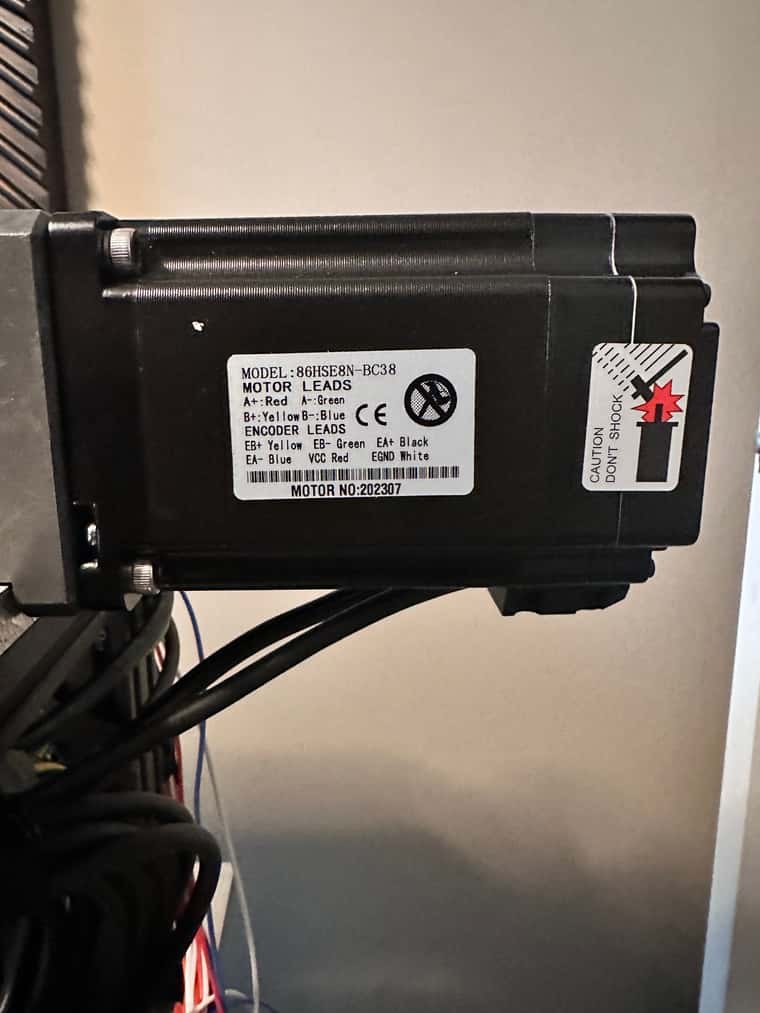
(7) checked the internal encoder wires at the back of the NEMA 34 motors and they are fine ,no crossings . They are correct as per the wiring listing on the side of the NEMA 34 motor
-
@developeralgo222 said in Configs for PCB PnP for Duet3D 6XD and 3 x 3HC expansion boards:
If M119 is reporting that the X and Y axis are at the max endstop, the axis won't move. Try changing the endstop configuration, removing the invert flag (
!), egM574 X2 S1 P"io0.in" ; configure switch-type (e.g. microswitch) endstop for low end on X via pin io0.in M574 Y2 S1 P"io1.in" ; configure switch-type (e.g. microswitch) endstop for low end on Y via pin io1.in The endstops should report 'not stopped' with M119, then, and the axis should be able to move. You can tell if it does move, because the machine position will change in DWC. If this moves, and your motors don't, then there's another reason, eg motor not actually enabled.
Alternatively, send
M564 H0 S0to allow axes to move that aren't homed, and allow axes to move outside the bounds of the printer. USE CAREFULLY! See https://docs.duet3d.com/en/User_manual/Reference/Gcodes#m564-limit-axesIan
-
@developeralgo222 I've also had a look at the HSS86 datasheet, and it doesn't have any information on timings to use beyond
frequency 0~200KHz
200KHz is a pulse and interval every 5us, so it should be able to do T2.5:2.5:10:10 (no information on the last two parameters, direction set up and direction hold).
Ian
-
@droftarts said in Configs for PCB PnP for Duet3D 6XD and 3 x 3HC expansion boards:
@developeralgo222 said in Configs for PCB PnP for Duet3D 6XD and 3 x 3HC expansion boards:
If M119 is reporting that the X and Y axis are at the max endstop, the axis won't move. Try changing the endstop configuration, removing the invert flag (
!), egM574 X2 S1 P"io0.in" ; configure switch-type (e.g. microswitch) endstop for low end on X via pin io0.in M574 Y2 S1 P"io1.in" ; configure switch-type (e.g. microswitch) endstop for low end on Y via pin io1.in The endstops should report 'not stopped' with M119, then, and the axis should be able to move. You can tell if it does move, because the machine position will change in DWC. If this moves, and your motors don't, then there's another reason, eg motor not actually enabled.
Alternatively, send
M564 H0 S0to allow axes to move that aren't homed, and allow axes to move outside the bounds of the printer. USE CAREFULLY! See https://docs.duet3d.com/en/User_manual/Reference/Gcodes#m564-limit-axesIan
Removed ! and tried again and X & Y are not moving at all. The X and Y are energized and the Motor is still in lock
-
@droftarts said in Configs for PCB PnP for Duet3D 6XD and 3 x 3HC expansion boards:
@developeralgo222 I've also had a look at the HSS86 datasheet, and it doesn't have any information on timings to use beyond
frequency 0~200KHz
200KHz is a pulse and interval every 5us, so it should be able to do T2.5:2.5:10:10 (no information on the last two parameters, direction set up and direction hold).
Ian
; Drives ;Physical Drives CAN ID = 0 M569 P0.0 S0 R1 T5:5:10:10 ; X-Axis physical drive 0.0 goes forwards on CAN ID = 0 - Duet 6XD Drive 0.0 with 5us timings between pulses M569 P0.1 S1 R1 T5:5:10:10 ; Y-Axis physical drive 0.1 goes forwards on CAN ID = 0 - Duet 6XD Drive 0.1 with 5us timings between pulses From the datasheet, Not sure if Dip Switch settings are supposed to be used, SW2=Direction , ON=CW, OFF = CCW
-
@developeralgo222 Does DWC update the motor position after you send a G1 command? Or any messages in the console? What does M119 report?
I usually send G92 X0 Y0 Z0 to set the axes as homed, then I don't have to send G1 H2 commands, just straight G1.
I'd leave the timing on T5:5:10:10, it shouldn't hurt. 2.5us is at it's limit.
Ian
-
@droftarts said in Configs for PCB PnP for Duet3D 6XD and 3 x 3HC expansion boards:
@developeralgo222 Does DWC update the motor position after you send a G1 command? Or any messages in the console? What does M119 report?
I usually send G92 X0 Y0 Z0 to set the axes as homed, then I don't have to send G1 H2 commands, just straight G1.
I'd leave the timing on T5:5:10:10, it shouldn't hurt. 2.5us is at it's limit.
Ian
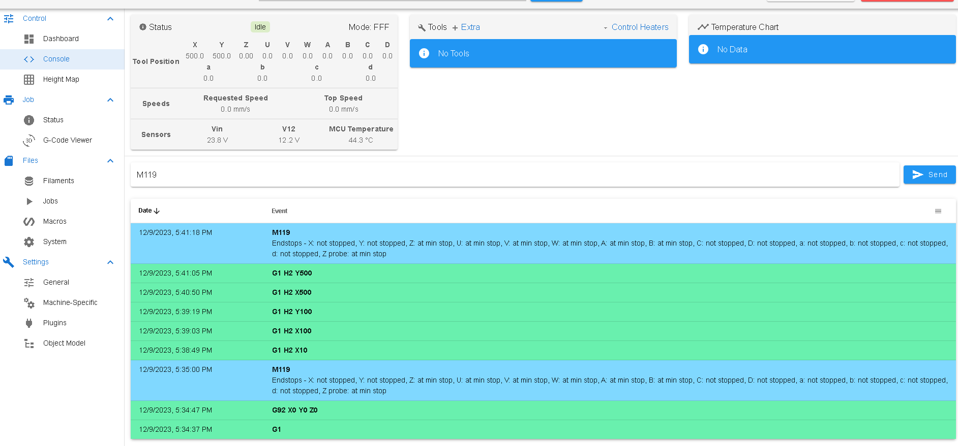
when i send a command like G1 H2 X10 , DWC will update the distance indicating X has moved but the Actual X motor does not spin to move on the X-axis , Same to Y-Axis
When i did send M119 after that
12/9/2023, 5:34:37 PM: G1 12/9/2023, 5:34:47 PM: G92 X0 Y0 Z0 12/9/2023, 5:35:00 PM: M119: Endstops - X: not stopped, Y: not stopped, Z: at min stop, U: at min stop, V: at min stop, W: at min stop, A: at min stop, B: at min stop, C: not stopped, D: not stopped, a: not stopped, b: not stopped, c: not stopped, d: not stopped, Z probe: at min stop 12/9/2023, 5:38:49 PM: G1 H2 X10 12/9/2023, 5:39:03 PM: G1 H2 X100 12/9/2023, 5:39:19 PM: G1 H2 Y100 12/9/2023, 5:40:50 PM: G1 H2 X500 12/9/2023, 5:41:05 PM: G1 H2 Y500 12/9/2023, 5:41:18 PM: M119: Endstops - X: not stopped, Y: not stopped, Z: at min stop, U: at min stop, V: at min stop, W: at min stop, A: at min stop, B: at min stop, C: not stopped, D: not stopped, a: not stopped, b: not stopped, c: not stopped, d: not stopped, Z probe: at min stop But still X and Y do not move at all .Not an even 1mm . They are energized and locked
DWC screen shows X and Y moved but nothing is moving.
-
@developeralgo222 I had a look at your wiring, and that looks correct. You mentioned earlier about the motor phases, did you check them? See https://docs.duet3d.com/en/User_manual/Connecting_hardware/Motors_connecting#identifying-the-stepper-motor-phases
Can you show how you have set the DIP switches? From what I can tell, they should be set as:
SW1 = on (86HSE8N motor)
SW2 = on (shouldn't matter, but clockwise)For the microstepping, you've told the Duet to expect 40 steps per mm, and 50mm per revolution. That would be 50x40 = 2000 steps per revolution. The drivers don't seem to have a setting for that, so try 3200. 3200/50 = 64 steps per mm. Change M92 to that, eg
M92 X64 Y64SW3 = off
SW4 = off
SW5 = on
SW6 = onNote that M350 (microstepping) and M906 (driver current) are irrelevant for external drivers
I've just noticed your jerk, acceleration and maximum speed! These may be way too fast, especially if the driver is on the default 400 steps per revolution. Most likely, it's receiving steps so fast it can't move!
M566 X900.0 Y900.0 Z900.0 U900.0 V900.0 W900.0 A900.0 B900.0 C100.0 D100.0 'A100.0 'B100.0 'C100.0 'D100.0 ; set maximum instantaneous speed changes (mm/min) M203 X126000.00 Y126000.00 Z24000.00 U24000.00 V24000.00 W24000.00 A24000.00 B24000.00 C24000.00 D24000.00 'A24000.00 'B24000.00 'C24000.00 'D24000.00 ; set maximum speeds (mm/min) M201 X50000.00 Y50000.00 Z500.00 U500.00 V500.00 W500.00 A500.00 B500.00 C5000.00 D5000.00 'A5000.00 'B5000.00 'C5000.00 'D5000.00 ; set accelerations (mm/s^2) All of these are really high, and it may be jerk + acceleration that is stalling the motor. Try:
M566 X300 Y300 M203 X5000 Y5000 M201 X1000 Y1000 If that works, you can test to see how much you can increase those speeds. Though I'd probably go for a higher microstepping value for more accuracy in the X and Y axes.
Ian
-
@droftarts said in Configs for PCB PnP for Duet3D 6XD and 3 x 3HC expansion boards:
@developeralgo222 I had a look at your wiring, and that looks correct. You mentioned earlier about the motor phases, did you check them? See https://docs.duet3d.com/en/User_manual/Connecting_hardware/Motors_connecting#identifying-the-stepper-motor-phases
Can you show how you have set the DIP switches? From what I can tell, they should be set as:
SW1 = on (86HSE8N motor)
SW2 = on (shouldn't matter, but clockwise)For the microstepping, you've told the Duet to expect 40 steps per mm, and 50mm per revolution. That would be 50x40 = 2000 steps per revolution. The drivers don't seem to have a setting for that, so try 3200. 3200/50 = 64 steps per mm. Change M92 to that, eg
M92 X64 Y64SW3 = off
SW4 = off
SW5 = on
SW6 = onNote that M350 (microstepping) and M906 (driver current) are irrelevant for external drivers
I've just noticed your jerk, acceleration and maximum speed! These may be way too fast, especially if the driver is on the default 400 steps per revolution. Most likely, it's receiving steps so fast it can't move!
M566 X900.0 Y900.0 Z900.0 U900.0 V900.0 W900.0 A900.0 B900.0 C100.0 D100.0 'A100.0 'B100.0 'C100.0 'D100.0 ; set maximum instantaneous speed changes (mm/min) M203 X126000.00 Y126000.00 Z24000.00 U24000.00 V24000.00 W24000.00 A24000.00 B24000.00 C24000.00 D24000.00 'A24000.00 'B24000.00 'C24000.00 'D24000.00 ; set maximum speeds (mm/min) M201 X50000.00 Y50000.00 Z500.00 U500.00 V500.00 W500.00 A500.00 B500.00 C5000.00 D5000.00 'A5000.00 'B5000.00 'C5000.00 'D5000.00 ; set accelerations (mm/s^2) All of these are really high, and it may be jerk + acceleration that is stalling the motor. Try:
M566 X300 Y300 M203 X5000 Y5000 M201 X1000 Y1000 If that works, you can test to see how much you can increase those speeds. Though I'd probably go for a higher microstepping value for more accuracy in the X and Y axes.
Ian
Updated the config.g, changed Drive Dip Switch settings for microstepping to SW1=ON, SW2=ON, SW3=OFF, SW4=OFF, SW5=ON, SW6=ON and attempted homing commands again and still no movement on X & Y axis
M350 Z16 U16 V16 W16 A16 B16 C16 D16 'A16 'B16 'C16 'D16 I1 ; configure microstepping with interpolation. This is irrelevant for external drives (X & Y ) M92 X64.00 Y64.00 Z8.888 U8.888 V8.888 W8.888 A8.888 B8.888 C8.888 D8.888 'A8.888 'B8.888 'C8.888 'D8.888 ; set steps per mm 50mm/rev M566 X300.0 Y300.0 Z300.0 U300.0 V300.0 W300.0 A300.0 B300.0 C100.0 D100.0 'A100.0 'B100.0 'C100.0 'D100.0 ; set maximum instantaneous speed changes (mm/min) M203 X5000.00 Y5000.00 Z5000.00 U5000.00 V5000.00 W5000.00 A5000.00 B5000.00 C5000.00 D5000.00 'A5000.00 'B5000.00 'C5000.00 'D5000.00 ; set maximum speeds (mm/min) M201 X1000.00 Y1000.00 Z500.00 U500.00 V500.00 W500.00 A500.00 B500.00 C1000.00 D1000.00 'A1000.00 'B1000.00 'C1000.00 'D1000.00 ; set accelerations (mm/s^2) M906 Z600.0 U600.0 V600.0 W600.0 A600.0 B600.0 C500.0 D500.0 'A500.0 'B500.0 'C500.0 'D500.0 I30 ; set motor currents (mA) and motor idle factor in per cent. This is irrelevant for external drives (X & Y ) -
@developeralgo222 I'm running out of ideas. As far as I can tell, there's nothing stopping the Duet sending step pulses to the motor driver, and it thinks the drive is moving, because the axis position is updated.
I am wondering if the motor energising is a red herring, and it's not actually enabling, because it's not going into an alarm condition:
ALM:Alarm indicator light: ... if the red light is flicker three times within 3 seconds, that means position ultra difference or the encoder connector is disconnected.
I don't think it's even registering it should move, because the driver is not enabled. Does the motor energise as soon as power is applied to the driver (with the Duet off), or only once the Duet is turned on?
How is the 3-pin 'Driver active enable select' jumper, next to Driver 1, set? I think the jumper is between EN_POL and GND, which should be correct for this drive:
The Enable output is either low when "on" and high impedance when "off", or vice versa, depending on the position of the 'Driver Enable Polarity' (En_Pol) jumper.
Also try changing M569 R parameter to R0:
Rnnn Driver enable polarity: 0 = active low, 1 = active high, -1 = driver is always disabled and is not monitored (default 0)
Another option is to try disconnecting +5V and -EN from the stepper driver, because external drivers are often active with no signal on the enable line, to allow for simpler systems which only have step and direction outputs.
The only other thing I can think of is to put an oscilloscope on the Duet outputs.
Ian
-
@developeralgo222 said in Configs for PCB PnP for Duet3D 6XD and 3 x 3HC expansion boards:
(2) M98 P"config.g" when sent it disconnects and nothing happens
I would start investigating this issue first, because it is a critical error. You might damage the onboard 5V regulator if it's a overcurrent shutdown...
Other stuff might solve itself after you've found the reason for the disconnects. -
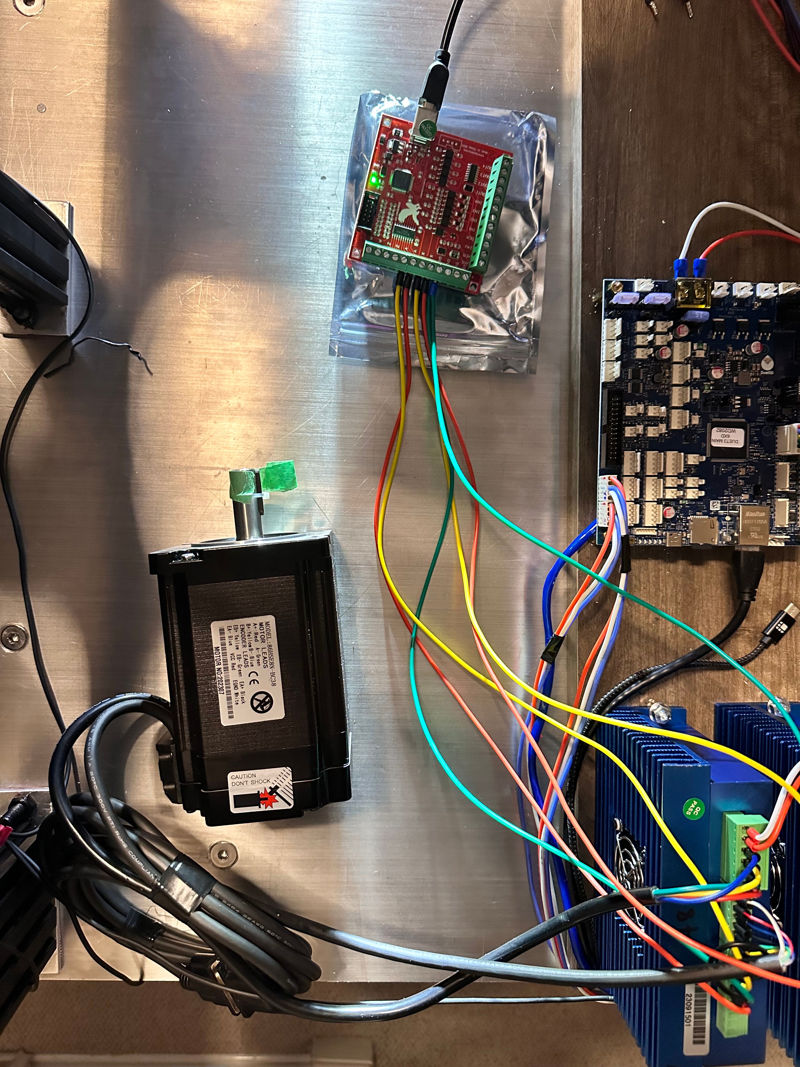
I finally got a MACH 3 Controller board and MACH 3 software to test the X & Y Axis motors( NEMA 34 8.5N.m (86HSE8N-BC38) ) and External Driver (HSS86) . The Motors work fine no issue they are able to move Left to Right on X-axis and Forward and back on Y-axis. Confirming that the following connections from Motor to Driver are correct (NEMA 34 Motor Power & Encoder connections) The only thing i changed for the test is the Signal wiring to comply with the MACH 3 Controller
On Duet 3 6XD
Signal Connection:
External Drive (HSS86) --------> (Cable Color) ------> Duet 3 6XD Drive_x
- PUL+ , DIR+, ENA+, ALM+ --------> (Red) ------> 5V_EXT
- PUL- --------> (Blue) ------> Dx_STEP-
- DIR- --------> (Yellow) ------> Dx_DIR-
- ENA- --------> (Green) ------> Dx_EN-
- ALM- --------> (Black) ------> Dx_ERR
On MACH 3 Control Board with USB Motion Driver RnRMotion.dll installed
Signal Connection:
External Drive (HSS86) --------> (Cable Color) ------> MACH 3 Controller X-axis
- PUL+ --------> (Red) ------> XP
- PUL- --------> (Green) ------> GND
- DIR+ --------> (Yellow) ------> XD
- PUL- to DIR - (Drive side only) ----> (Black)
It seems on MACH 3 if you compare it to Duet 6XD connections it seems they are reversed as @droftarts mentioned
- PUL+ --------> (Red) ------> XP ( Dx_STEP+ )
- DIR+ --------> (Yellow) ------> XD ( Dx_DIR+ )
- ENA+ --------> (Blue) ------> XE ( Dx_ENA+ ) ******?
- ALM+ --------> (Black) ------> XA ( Dx_ALM+ ) ******?
- PUL- , DIR-, ENA- , ALM- --------> (Green) ------> GND
It seems the issue is on the Duet 3 6XD side configuration and the signal connection from the external drive. Not sure how to do this on Duet 6XD
-
@developeralgo222 it looks like the driver is switched the other way around from ‘normal’ drivers, in that it needs a +5V signal with a common ground, rather than having a common +5V that is pulled to ground by a signal. It’s a shame the data sheet is so sparse on details. Where did you find the info on wiring up the Mach 3 controller?
I’ll have to ask @dc42 in the morning if the 6XD can do that.
If you are thinking it’s a configuration error, especially if sending
M98 P"config.g"causes a reset, create a basic config.g that only sets the X and Y axes.Ian
-
@droftarts said in Configs for PCB PnP for Duet3D 6XD and 3 x 3HC expansion boards:
@developeralgo222 it looks like the driver is switched the other way around from ‘normal’ drivers, in that it needs a +5V signal with a common ground, rather than having a common +5V that is pulled to ground by a signal. It’s a shame the data sheet is so sparse on details. Where did you find the info on wiring up the Mach 3 controller?
Just on youtube and google search , an online user made a demo on how to test the same setup on youtube and someone explained how to connect MACH 3 controller and to NEMA 34 motors
MACH 3 Controller connection to HSS86 Drive + Nema 34 closed Motor
MACH3 Controller installation and Wiring
This is a very simple NEMA 34 closed Loop/External Drive connection to 6XD not sure why it would not work