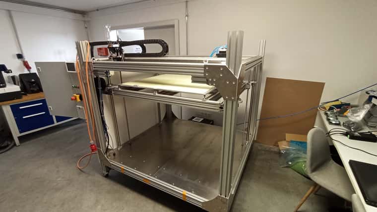
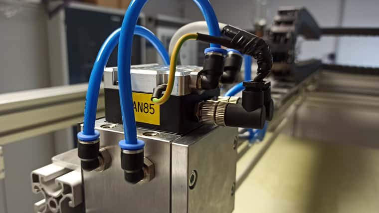
Large 3D printer build! Hardware discussion and ideas
-
Hi,
Thanks for the replies already! I'll try to answer your points in order.
@soare0 said in Large 3D printer build! Hardware discussion and ideas:
- I would say that bed temperature would be the smallest problem of yours right now, but hey...!
To answer your question, unless you have 4 heating heating pads, each one with its own thermistor, why would you want to control separately each of them, and not wire them to the same SSR for power, and use just one thermistor?
Even with 4 thermistors, factory mounted for each pad, you have two solutions: use only one of them, or group them, 2 parallel groups in series. One of these ways would spare many thermistor inputs...
I would say that many heating zones on the bed may be useful, but not in the manner you indicated in the picture, but with some outer ring and inner core, and even then, you may run into troubles, as I am not sure that RRF can manage something wich need such control complexity (fuzzy control, zone correlation, so on). Still, it may be doable with Duet, just not sure, but anyway, you have my 2c already.- I did group the bed into 4, because a) most of the time we're only gonna use the size of one, or two at a time, no need for the remaining area to waste the energy and b) I don't want to use one large sheet of metal to avoid the worst warping that may occur.
So I just place the part in the slicer according to the heated area, and select the zones on the machine manually (doesn't even need to be automated)
- I would suggest to use 4 motors for this area, with only 2 axial bearing rods. Mine is only 600x600 and it is very useful to have 4 motors. You will only need for a CAN board for extruder, in this case, as 6XD will be ... full .
- I'm using 4 rods and even then I think it may be the wrong approach, the bed will be HEAVY even empty, plus considering a THICK part on it, and I'm worried about ballscrew wobble and to keep it properly oriented in XY directions.
I considered 4 motors actually, to make proper use of bed tramming, but I figured it's just a luxury at this point. May add later but since we're building rough parts with large nozzles I don't worry atm
Still, probably it depends of the rigidity of your bed, but I would not be worried about it, at these dimensions.
3. Why use CAN for motors when have 6XD? You only need some external drivers for motors, these being more fast accurate and not prone to eventual CAN errors.- because the Duet motors offer that feature plus internal drivers, and it's a good way to cut down on wiring chaos
- On Y, you want two rails, and 2 belts, driven from the same motor preferably, via a shaft. The motor can be fitted on the backplane of the printer (interior wall). Having two motors is possible, using two drivers controlled by the same signal (wich can be done for Z too, but you will loose the automated leveling possibility). Still, with two motors, even paralleled through drivers, well ... pray for luck (if not closed loop).
- That's what I tried to avoid, so I'm using one motor, two belts, two rails and synced via a shaft. Our ISEL mill works that way, so I just copied it
- I do not understand exactly why do you want to use brake motors for Z, as it is almost impossible, given the right diameter for screws and the size of the motors. This will only complicate things, unless... well, unless you know why.
- brakes are an absolute necessity on this scale, the bed will crash down no matter what as soon as power is cut to the motors. From my understanding, they are controlled via CAN as well, so they don't even need extra wires. The motors are mounted sideways, so the belt just needs to be twisted 90°, and space is no longer an issue

- Use polycarbonate removable for the to upper lateral sections. You will need this.
- Yes, the plan is to make the upper section removable and see-thru, but no solid plans on how to execute best atm.
7.Let PI4 for after the rest of your printer will work flawlessly. Do it standalone for beginning.
- For sure
-
On the top, you will want 1-2 removable panels/hinged doors, with polycarbonate window. Now, of course that the front door will be polycarbonate too, and probably sectioned.
-
If you want to work up to 80C at this volume, you may want some insulation on the inside. Still, depending on what you want to do, sometimes, especially because on insulation, you may also want a cooling duct/fan, wich be thermostatic controlled. Also, consider from start excellent quality belts, maybe rated to 120C, and the same for all bearings.
- I want to use 16mm isolated panels for the enclosure, sidewalls and on top; the large doors at the front probably use the same material plus isolated glass windows
- My 600x600 is working on glass bed, while I must admit that this is a real pain many times. Your choice may be better, but I do not know how it will fare with expansion. I am still curious why would want to work with FR4 and 80C inside (for PC maybe?), as PC needs even 130C for bed, and FR4 or such, it is not such a great ideea to work with, at these temperatures, for long time, even the HT versions (not the yellow one, anycase).
- I just thought I'd give it a shot, cause it works great on my smaller printers up to 80° C on a regular basis with no issues and it's relatively stiff/cheap so even If it gets messed up. And the surface texture may help greatly with adhesion.
The large glass bed on DrD-Flo's large printer (diy on youtube) shattered from the material warping
You will need anyway some smart ways to fix the build plate, to ensure planeity for such area. On my glass, I have up to 0.35mm differences... As it is for big stuff, it does not really matters, but even so, babysteps comes handy many times.
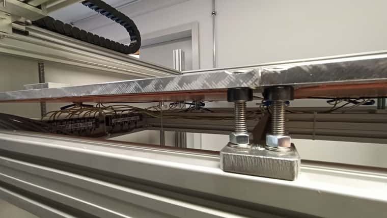
*** my idea was to push it underneath recessed blocks at the back and on the left, and bolt recessed blocks to the right and to the front after installation to hold it in position**
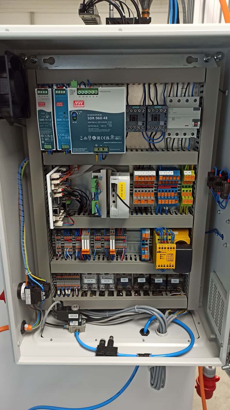
- You forgot the power supply for PI. I would not use the 6XD for that, even if possible. The 12V PSU may be useful for some fans, I used it for some water cooling pump, as the 12V PSU on 6XD is ... for Tinkerbell like stuff.
- I just didn't mention it, I bought one of course

Being in your place, I would have bought a large DoWell printer (wich in fact I did), and send electronics on the bin (except motor drivers and cables), replacing belts and bearings (as they are junk). Eventually one not enclosed, as this would be cheaper, depending on version. But as you already have bought much, maybe it is better to follow ... the hard way you are following now.
- Actually considered many routes, for what makes the most sense. Thing is, you never know what you'll get with the chinese stuff; you can't check it out beforehand, etc.. plus adding all the shipping and taxes and customs, plus the extra modification time and cost, is it really making sense. Plus, my design already existed from years ago, I just had to get back to it. And my boss prefers building stuff, I'm fine with that

Note: if you are not experienced in hardware and coding, just do not do it, buy one. The project is not for .... faint of heart. I already saw on the forum, at least two ... lost cases with such builds, because it was a ... too far strech for them.
Still, if you have already built smaller 3d printers, and got your nose into marlin/klipper, you may be safe. I would wish you luck, but as this only depends on your skills... I wish you skills!- skills are mostly there my man
 I'm years into marlin and 3D printing stuff at home, geeking out on all things tech, fixing cars, RC airplane stuff for decades... I'm just diving into python, just all that Duet stuff is new for me. But I rather chose that platform instead of going full industry standard drives, because I would have a lot to chew with those that's for sure.
-
@T3P3Tony said in Large 3D printer build! Hardware discussion and ideas:
@Danny-Jay said in Large 3D printer build! Hardware discussion and ideas:
My first nagging question would be, how I could possibly manage the four heating zones via the Duet, of course each one gets his own feed via SSR and each has it's own temp. probe (and fuse of course)
its is possible to setup multiple heated beds using M140 P0 H0, M140 P1 H1 etc up to 4. The UI (DWC) has the option to group these beds into one "logical" bed to make it easier for the user. That is not the case on PanelDue though.
That sounds like we're in the right ballpark so I'm kinda relieved

Thanks

-
@Danny-Jay said in Large 3D printer build! Hardware discussion and ideas:
The large glass bed on DrD-Flo's large printer (diy on youtube) shattered from the material warping
Maybe a bad bed design? One should always consider thermal expansion for the bed, especially for these dimensions. FR4... if it works at 130C for small sizes, it will work for this too... I think. When mentioning 80C internal, I assumed you are working with PC, so... not 80C was the issue.
@Danny-Jay said in Large 3D printer build! Hardware discussion and ideas:
brakes are an absolute necessity on this scale, the bed will crash down no matter what as soon as power is cut to the motors. From my understanding, they are controlled via CAN as well, so they don't even need extra wires. The motors are mounted sideways, so the belt just needs to be twisted 90°, and space is no longer an issue
Indeed, I did not tried to print a 60kg part, for example. Also, I have 4 screws, and 4 motors.
@Danny-Jay said in Large 3D printer build! Hardware discussion and ideas:
because the Duet motors offer that feature plus internal drivers, and it's a good way to cut down on wiring chaos
I would not give so much consideration to wiring.
@Danny-Jay said in Large 3D printer build! Hardware discussion and ideas:
I considered 4 motors actually, to make proper use of bed tramming, but I figured it's just a luxury at this point.
Haha, use then 2 bigger rods and 4 motors. It is a luxury, one can do manual leveling anyway. if needed, even in large printers. But it is not such a big issue.
@Danny-Jay said in Large 3D printer build! Hardware discussion and ideas:
So I just place the part in the slicer according to the heated area, and select the zones on the machine manually (doesn't even need to be automated)
If it does not need to be automated, you may do a holder for thermistor and moving it as needed. You may encounter temperature gradients if you will use only one zone, in your configuration, because of the big size of the unheated bed, Maybe I am wrong though...
Good luck then, if skills are there.
-
@Danny-Jay said in Large 3D printer build! Hardware discussion and ideas:
brakes are an absolute necessity on this scale, the bed will crash down no matter what as soon as power is cut to the motors.
Have you considered using a belt lifted Z axis? I used a 30:1 worm gear reducer to stop bed movement when power to the z axis motor is cut. It's very simple- no brakes, no external motor drivers, and no fancy configuration are required. I run the motor at 1A (driven by the driver on the Duet 2 controller board) and it has no trouble lifting 7.5 kg (that's as far as I have tested it.). Running the motor closer to rated current will probably allow a very heavy load to be lifted. If you use 30 tooth pulleys you'll get 10 um movement per full step from the motor.
When power is cut, the bed doesn't move. It might jump a tiny bit when power is restored, but you should be able to resume prints with a minor z artifact at the point where power failed and was restored (assuming the print remained attached to the bed, and that you used a single motor to lift the bed).
-
@Danny-Jay said in Large 3D printer build! Hardware discussion and ideas:
I'm worried about ballscrew wobble and to keep it properly oriented in XY directions.
I'd mount the ballscrews and Z-motors on the top. The motor wires are shorter and the ballscrews are working in a pull-fashion. Gravity will help keeping them oriented.
-
@o_lampe Normally, the ball screws are not fitted directly to motors on such printers, but through a GT belt, so both ends of the ball screws are supportedwoth ball bearings. Also, this helps with increasing resolution, as on Y one do not need high speeds anyway. I will upload some photos, and let a link for such mechanics, later.
-
Hi there,
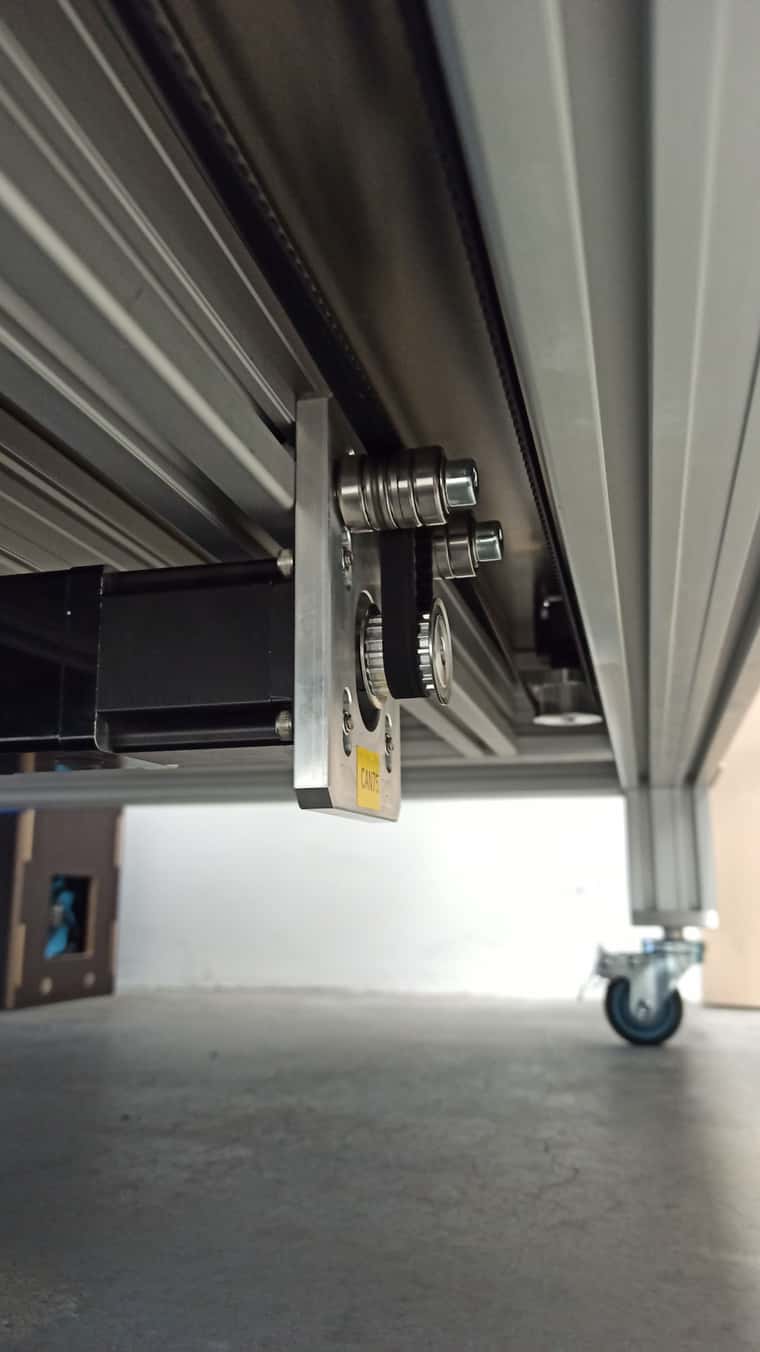
Thanks for the replies! I'm going to add a bottom view picture of the Z drive :
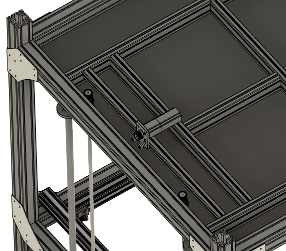
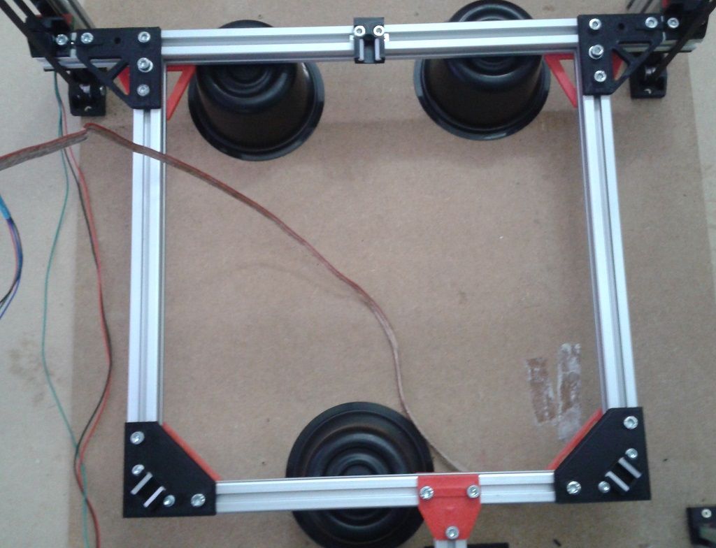
There will be a GT belt synchronizing two ballscrews, with the motor sideways (twisted belt) to accomodate this chonker down there. I wanted to keep them at the bottom, because I'm already going to have to deal with proper cooling of the XY drives up in the chamber. This way they can mind their own business down there at room temperature

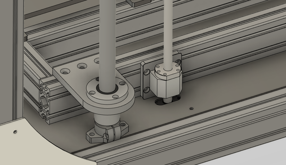
The slots at the base plate allow for belt tensioning. Don't mind the rudimentary axial roller installation too much; it'll be neatly cnc'ed once it's confirmed working (i'll swear
 )
)Dan
-
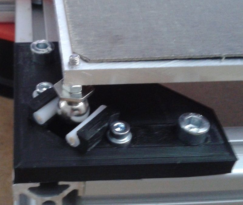
@Danny-Jay I hope you keep thermal expansion of the bed in mind. Four axial bearings with fixed position is not the best idea.
Even on smaller beds, floating joints keep the bed from warping under thermal stress.
-
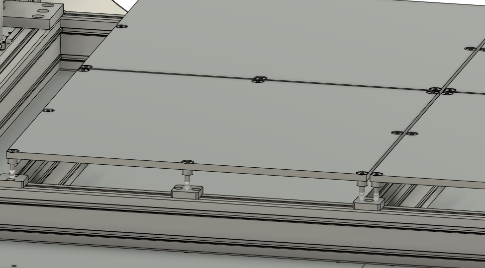
That's why I split up the bed into 4 zones; And installed them on comparably ´flexible´studs, which also allow for a precise first leveling. There will be nuts down at the thread to secure them once set.
Your method of installation seems very appealing to me!
-
I kinda did, firstly because I'm lazy and belts solve a lot of points at once with little parts count. On the other hand, I wasn't too sure about flex, and temperature expansion, considering possibly very heavy prints to an extend. So I went with the ´missionary´-way of things, haha. Just works that way.
Do you have any pictures of your design ?
-
@Danny-Jay I used 60 tooth drive pulleys for the Z axis in my printer which yields 20 um per full step, and I slew the Z axis at 15 mm/sec (I think it could do 20). Using 30 tooth pulleys would take that to 10 um per full step and slow it down a little. My printer uses two belts to lift the Z axis and measurements show belt stretch is inconsequential. If you use 4 belts instead of two you can expect less stretch. I haven't tested the limits, but I suspect that motor, running at 80% of rated current, could lift 30-40 kg without problems.
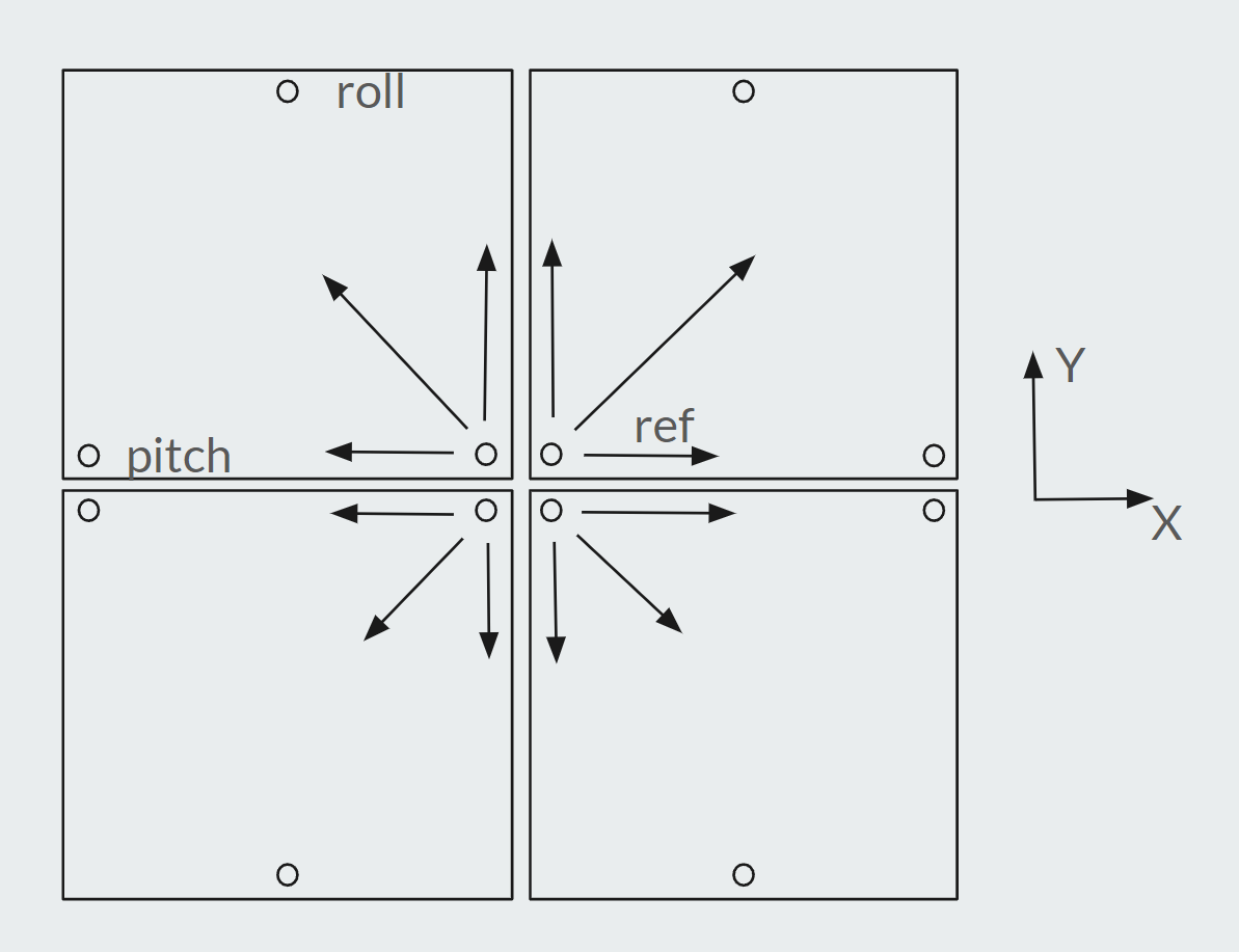
I don't think using flexible stud mounts for the bed plates is a good idea. If the studs flex, the plates will move in Z. It would be more stable to put the plates on kinematic mounts. They will be able to expand without bending anything and maintain constant Z position regardless of temperature. If you put the reference adjuster positions all near the center of the 4 plates, the plates will be free to expand outward. I would use kinematic mounts even if you plan to use bed flatness compensation.
In the pages linked above there are some updates- be sure to check them out as some changes were made after the original blog posts.
-
@Danny-Jay Thermal expansion also happens to the frame. Especially when you combine steel/aluminum parts, it can warp or bind (linear rails)
-
@mrehorstdmd Well I've used the term `flexible´ as kind of a stretch. They're stainless M8 shanked bolts which, considering how far they stick out, provide some radial give for the few tenths of expansion whilst being stiff in Z direction. At least that seems theoretically plausible. I'll need to check for flatness when everything's heated up properly. In the end, when everythings chambered in and heated equally, there should be little concern of parts binding up. Yet, I haven't worked with such material lengths and amounts before to be eventually an 'oven' (stretch) in the end.
Could anyone provide an insight, if sensorless homing is an option on Duet paired with Duet closed loop steppers?
That way I don't need to look out for endstop sensors that can cope with higher temps! -
@Danny-Jay said in Large 3D printer build! Hardware discussion and ideas:
Could anyone provide an insight, if sensorless homing is an option on Duet paired with Duet closed loop steppers?
Sensorless homing is not currently supported on axis motors attached to expansion boards. It's likely to be supported in firmware 3.6.
What temperature do you intend to heat the chamber to?
-
@Danny-Jay You haven't said how large the bed plates are, but 300 mm plates expand by about 0.5 mm when heated from 25 to 105C (ABS print temperature). The underlying support frame will not be as hot so it will expand much less. That's going to force something to flex, and that will move the bed plates in Z.
If you put each plate on a kinematic mount, and put the reference points at the center of the group, the plates will expand outward. The kinematic mounts will allow that expansion without forcing anything to flex. The spacing between the plates will remain almost exactly constant. You will need a hole in each plate at the reference adjuster and a short slot at the pitch adjuster aligned parallel to the X axis of the printer, and a screw that touches the bottom of each plate at the roll adjuster point. You'll also need springs to hold each plate down on the pitch and roll adjuster screws.
With this arrangement, heating one or two of the plates for a small print won't create any problems.
-
@mrehorstdmd I'm gonna implement that, quite adaptable to the current design. The plates are 530mm, 10 thick, quite large actually.
@dc42 Thanks, the chamber may go up to 80° C. My current sensors are rated up to 50 deg. Of course I could just use simple clicky switches. But that's pretty basic
-
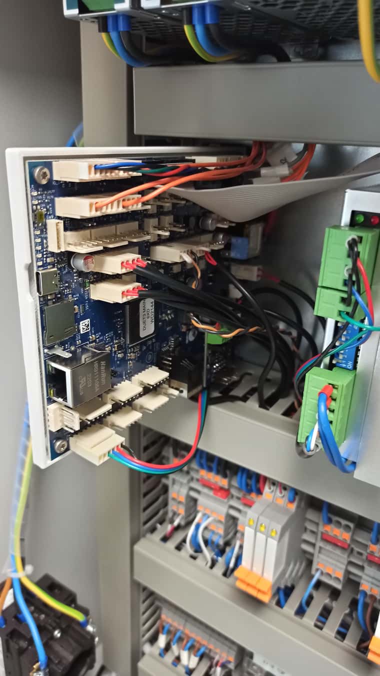
Hey guys!
Jumping right in to post some update pictures of the current state, it's pretty close to the final wiring ( yuck!)
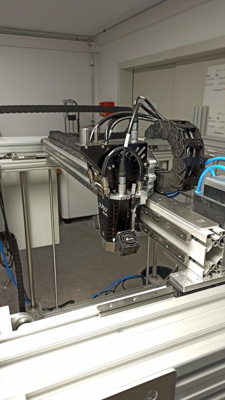
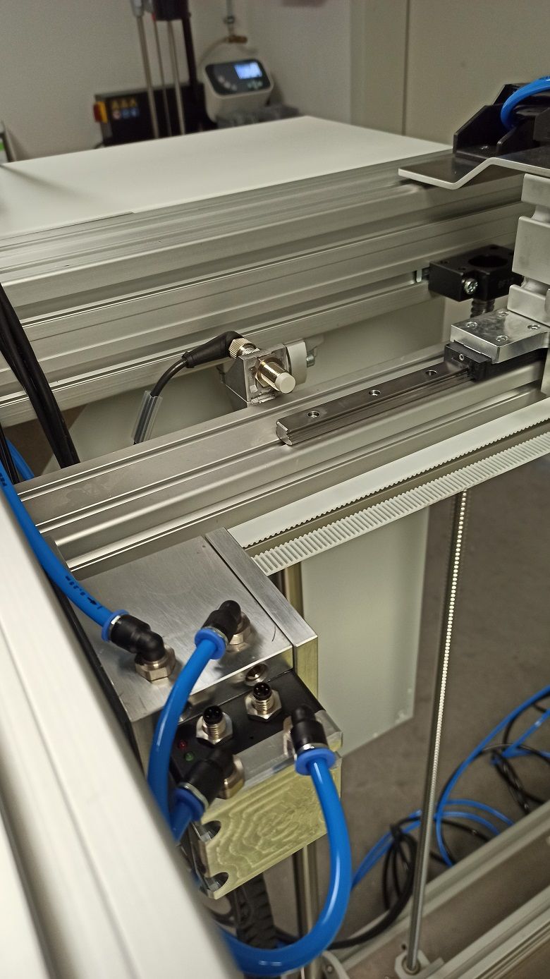
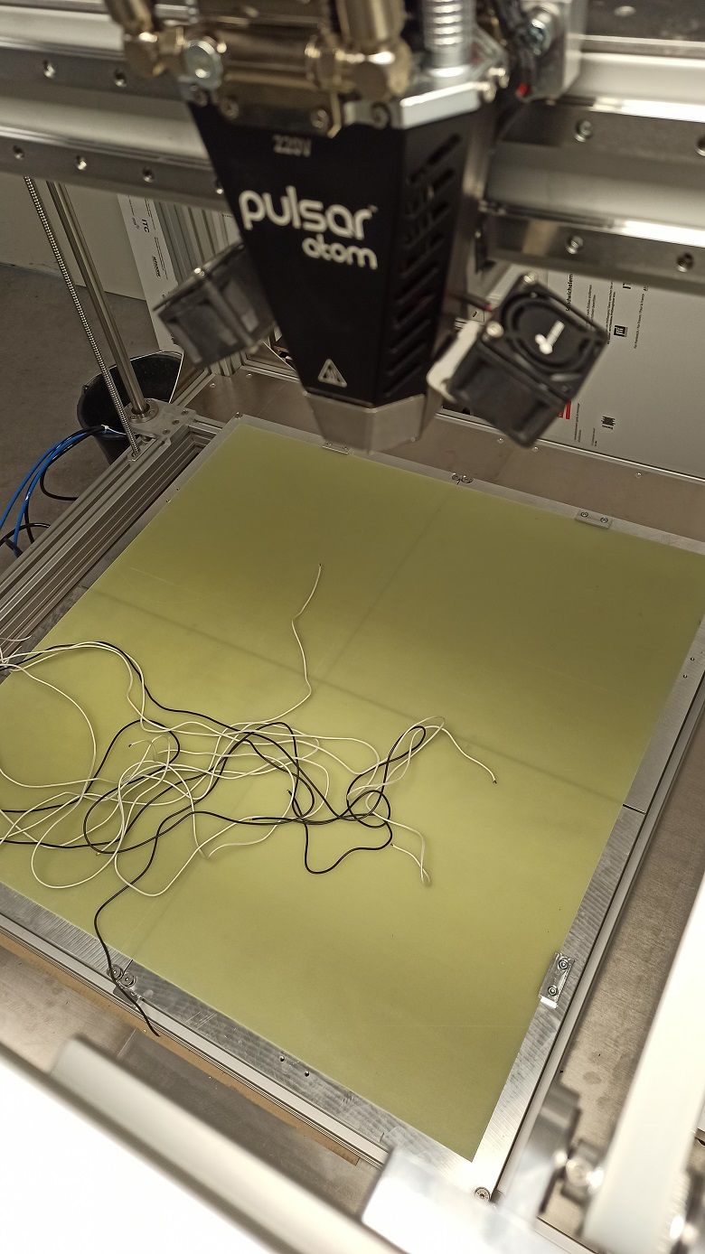
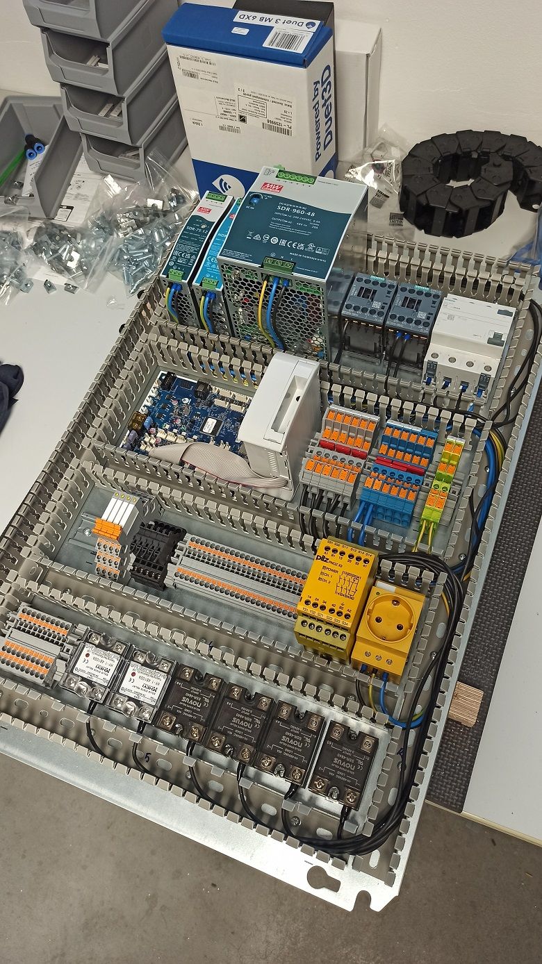
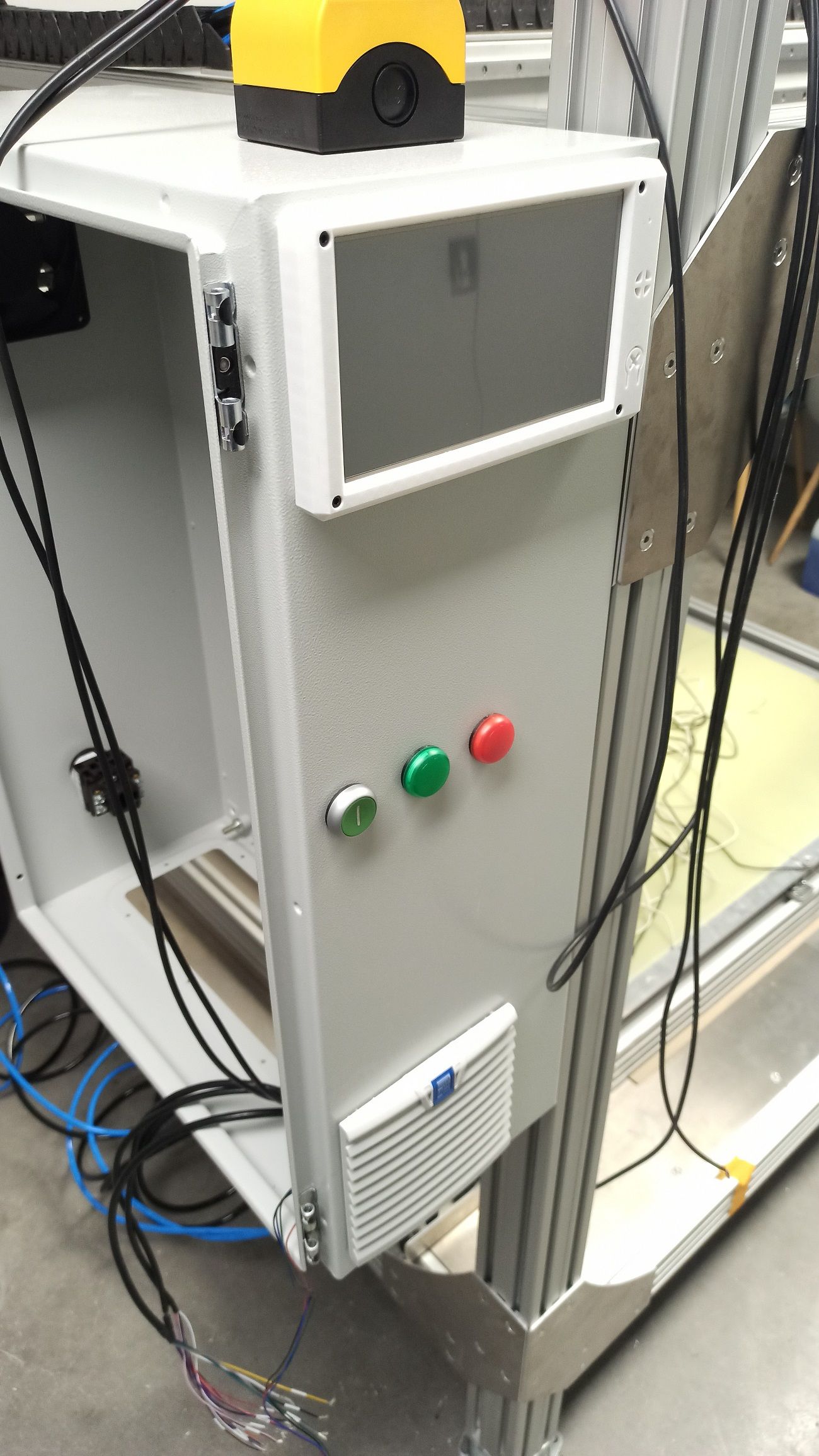
Does anybody know how far the Duet inductive bed probe does travel in terms of distance to a metal surface?
-
Status update,
The machine is now up and running, yet not completed but good for now running some experiments
Test move:
https://youtube.com/shorts/3CKMNepaWuw?si=1G-3YxQf6VK5LicsProbing:
https://youtube.com/shorts/EADCz_VwGls?si=ZgHFzYnbh_czCJaQ