Large 3D printer build! Hardware discussion and ideas
-
@Danny-Jay said in Large 3D printer build! Hardware discussion and ideas:
brakes are an absolute necessity on this scale, the bed will crash down no matter what as soon as power is cut to the motors.
Have you considered using a belt lifted Z axis? I used a 30:1 worm gear reducer to stop bed movement when power to the z axis motor is cut. It's very simple- no brakes, no external motor drivers, and no fancy configuration are required. I run the motor at 1A (driven by the driver on the Duet 2 controller board) and it has no trouble lifting 7.5 kg (that's as far as I have tested it.). Running the motor closer to rated current will probably allow a very heavy load to be lifted. If you use 30 tooth pulleys you'll get 10 um movement per full step from the motor.
When power is cut, the bed doesn't move. It might jump a tiny bit when power is restored, but you should be able to resume prints with a minor z artifact at the point where power failed and was restored (assuming the print remained attached to the bed, and that you used a single motor to lift the bed).
-
@Danny-Jay said in Large 3D printer build! Hardware discussion and ideas:
I'm worried about ballscrew wobble and to keep it properly oriented in XY directions.
I'd mount the ballscrews and Z-motors on the top. The motor wires are shorter and the ballscrews are working in a pull-fashion. Gravity will help keeping them oriented.
-
@o_lampe Normally, the ball screws are not fitted directly to motors on such printers, but through a GT belt, so both ends of the ball screws are supportedwoth ball bearings. Also, this helps with increasing resolution, as on Y one do not need high speeds anyway. I will upload some photos, and let a link for such mechanics, later.
-
Hi there,
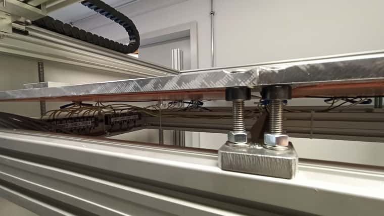
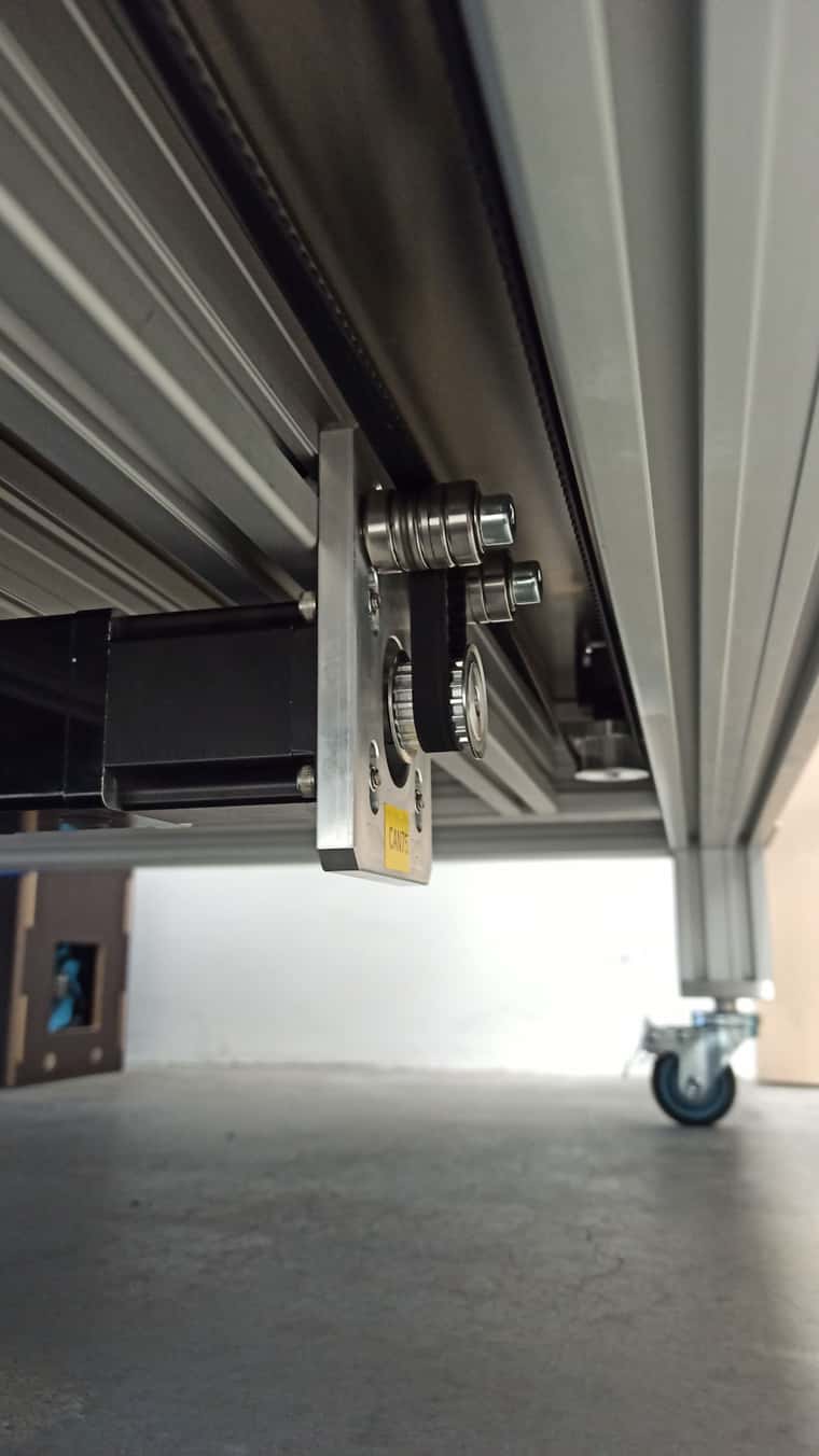
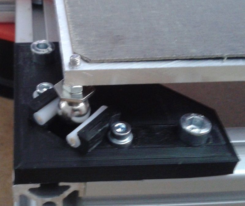
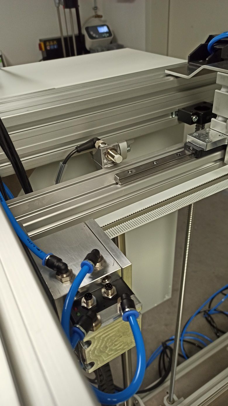
Thanks for the replies! I'm going to add a bottom view picture of the Z drive :
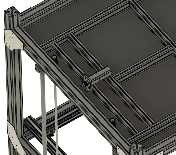
There will be a GT belt synchronizing two ballscrews, with the motor sideways (twisted belt) to accomodate this chonker down there. I wanted to keep them at the bottom, because I'm already going to have to deal with proper cooling of the XY drives up in the chamber. This way they can mind their own business down there at room temperature
")
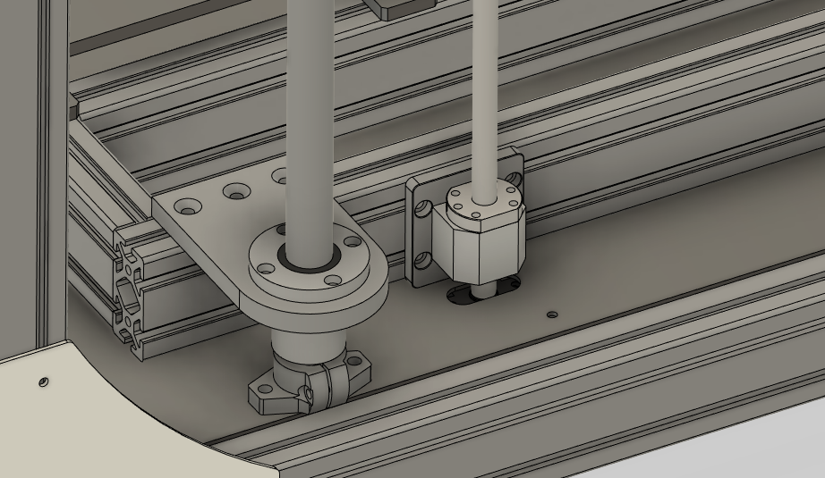
The slots at the base plate allow for belt tensioning. Don't mind the rudimentary axial roller installation too much; it'll be neatly cnc'ed once it's confirmed working (i'll swear
 )
)Dan
-
@Danny-Jay I hope you keep thermal expansion of the bed in mind. Four axial bearings with fixed position is not the best idea.
Even on smaller beds, floating joints keep the bed from warping under thermal stress.
-
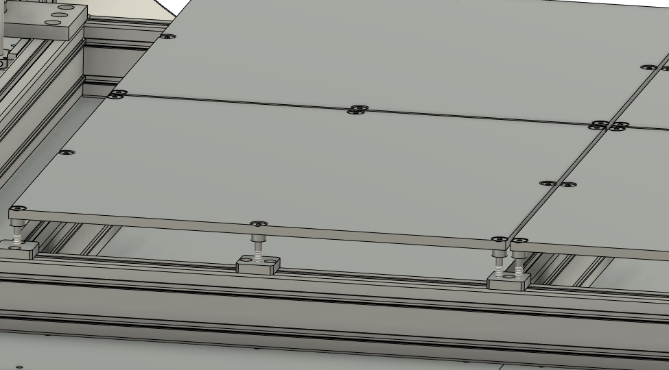
That's why I split up the bed into 4 zones; And installed them on comparably ´flexible´studs, which also allow for a precise first leveling. There will be nuts down at the thread to secure them once set.
Your method of installation seems very appealing to me!
-
I kinda did, firstly because I'm lazy and belts solve a lot of points at once with little parts count. On the other hand, I wasn't too sure about flex, and temperature expansion, considering possibly very heavy prints to an extend. So I went with the ´missionary´-way of things, haha. Just works that way.
Do you have any pictures of your design ?
-
@Danny-Jay I used 60 tooth drive pulleys for the Z axis in my printer which yields 20 um per full step, and I slew the Z axis at 15 mm/sec (I think it could do 20). Using 30 tooth pulleys would take that to 10 um per full step and slow it down a little. My printer uses two belts to lift the Z axis and measurements show belt stretch is inconsequential. If you use 4 belts instead of two you can expect less stretch. I haven't tested the limits, but I suspect that motor, running at 80% of rated current, could lift 30-40 kg without problems.
I don't think using flexible stud mounts for the bed plates is a good idea. If the studs flex, the plates will move in Z. It would be more stable to put the plates on kinematic mounts. They will be able to expand without bending anything and maintain constant Z position regardless of temperature. If you put the reference adjuster positions all near the center of the 4 plates, the plates will be free to expand outward. I would use kinematic mounts even if you plan to use bed flatness compensation.
In the pages linked above there are some updates- be sure to check them out as some changes were made after the original blog posts.
-
@Danny-Jay Thermal expansion also happens to the frame. Especially when you combine steel/aluminum parts, it can warp or bind (linear rails)
-
@mrehorstdmd Well I've used the term `flexible´ as kind of a stretch. They're stainless M8 shanked bolts which, considering how far they stick out, provide some radial give for the few tenths of expansion whilst being stiff in Z direction. At least that seems theoretically plausible. I'll need to check for flatness when everything's heated up properly. In the end, when everythings chambered in and heated equally, there should be little concern of parts binding up. Yet, I haven't worked with such material lengths and amounts before to be eventually an 'oven' (stretch) in the end.
Could anyone provide an insight, if sensorless homing is an option on Duet paired with Duet closed loop steppers?
That way I don't need to look out for endstop sensors that can cope with higher temps! -
@Danny-Jay said in Large 3D printer build! Hardware discussion and ideas:
Could anyone provide an insight, if sensorless homing is an option on Duet paired with Duet closed loop steppers?
Sensorless homing is not currently supported on axis motors attached to expansion boards. It's likely to be supported in firmware 3.6.
What temperature do you intend to heat the chamber to?
-
@Danny-Jay You haven't said how large the bed plates are, but 300 mm plates expand by about 0.5 mm when heated from 25 to 105C (ABS print temperature). The underlying support frame will not be as hot so it will expand much less. That's going to force something to flex, and that will move the bed plates in Z.
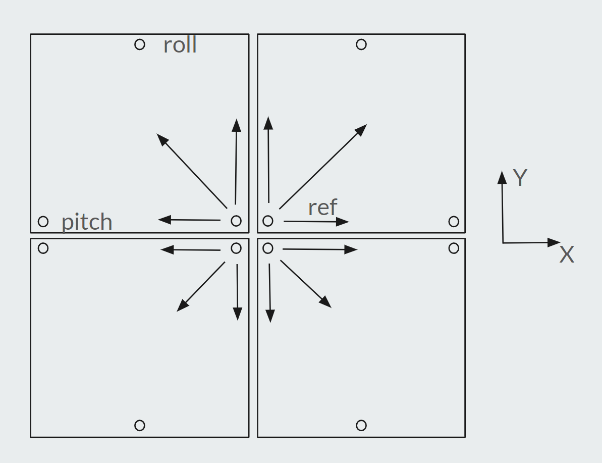
If you put each plate on a kinematic mount, and put the reference points at the center of the group, the plates will expand outward. The kinematic mounts will allow that expansion without forcing anything to flex. The spacing between the plates will remain almost exactly constant. You will need a hole in each plate at the reference adjuster and a short slot at the pitch adjuster aligned parallel to the X axis of the printer, and a screw that touches the bottom of each plate at the roll adjuster point. You'll also need springs to hold each plate down on the pitch and roll adjuster screws.
With this arrangement, heating one or two of the plates for a small print won't create any problems.
-
@mrehorstdmd I'm gonna implement that, quite adaptable to the current design. The plates are 530mm, 10 thick, quite large actually.
@dc42 Thanks, the chamber may go up to 80° C. My current sensors are rated up to 50 deg. Of course I could just use simple clicky switches. But that's pretty basic
-
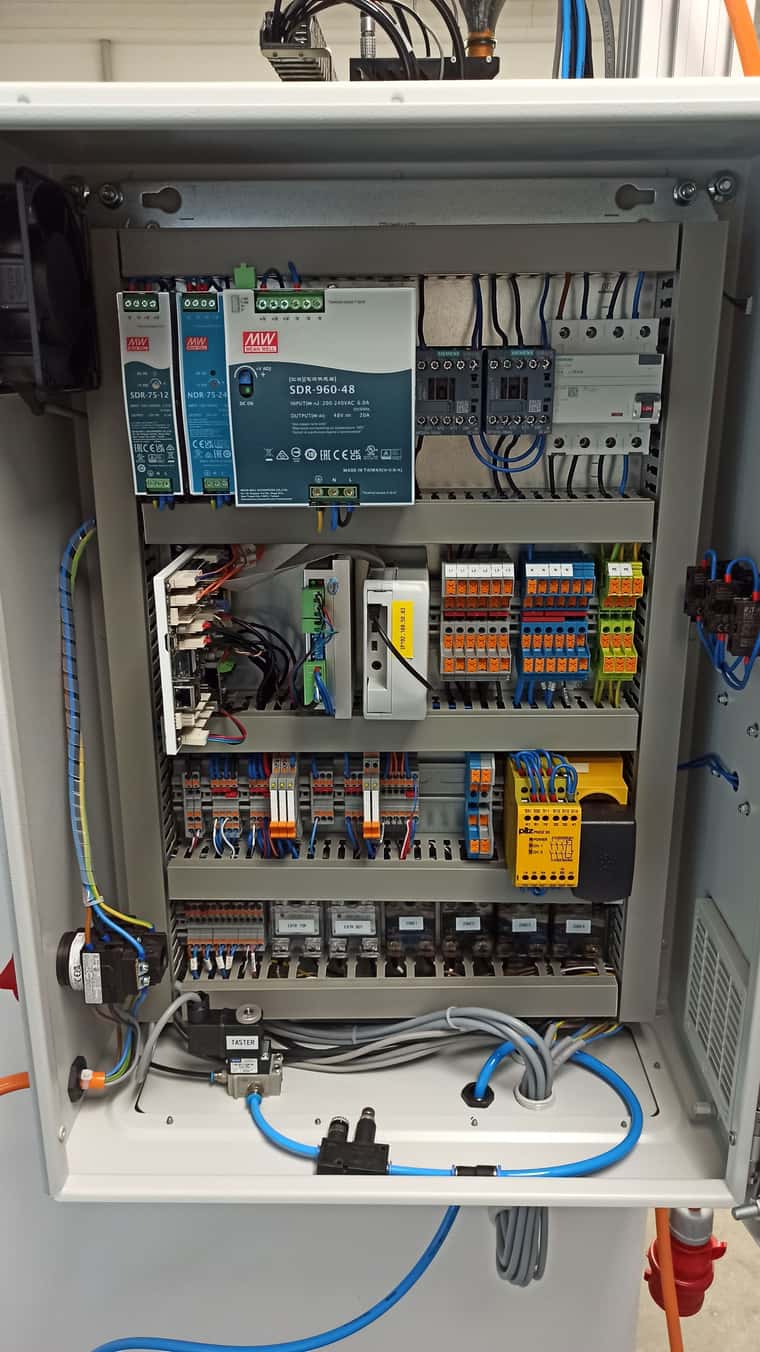
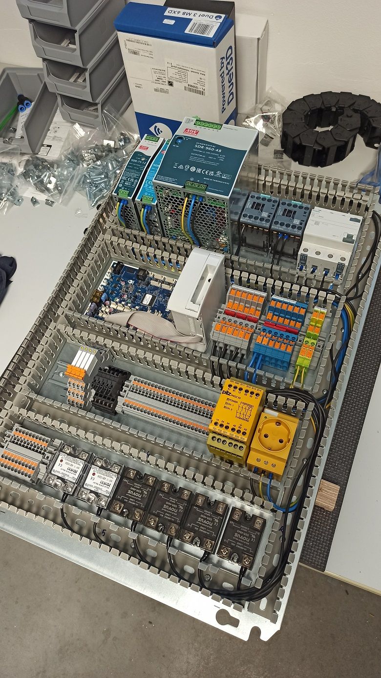
Hey guys!
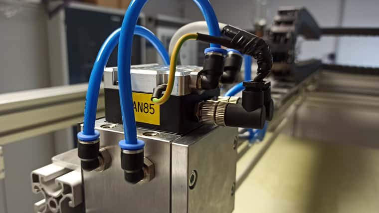
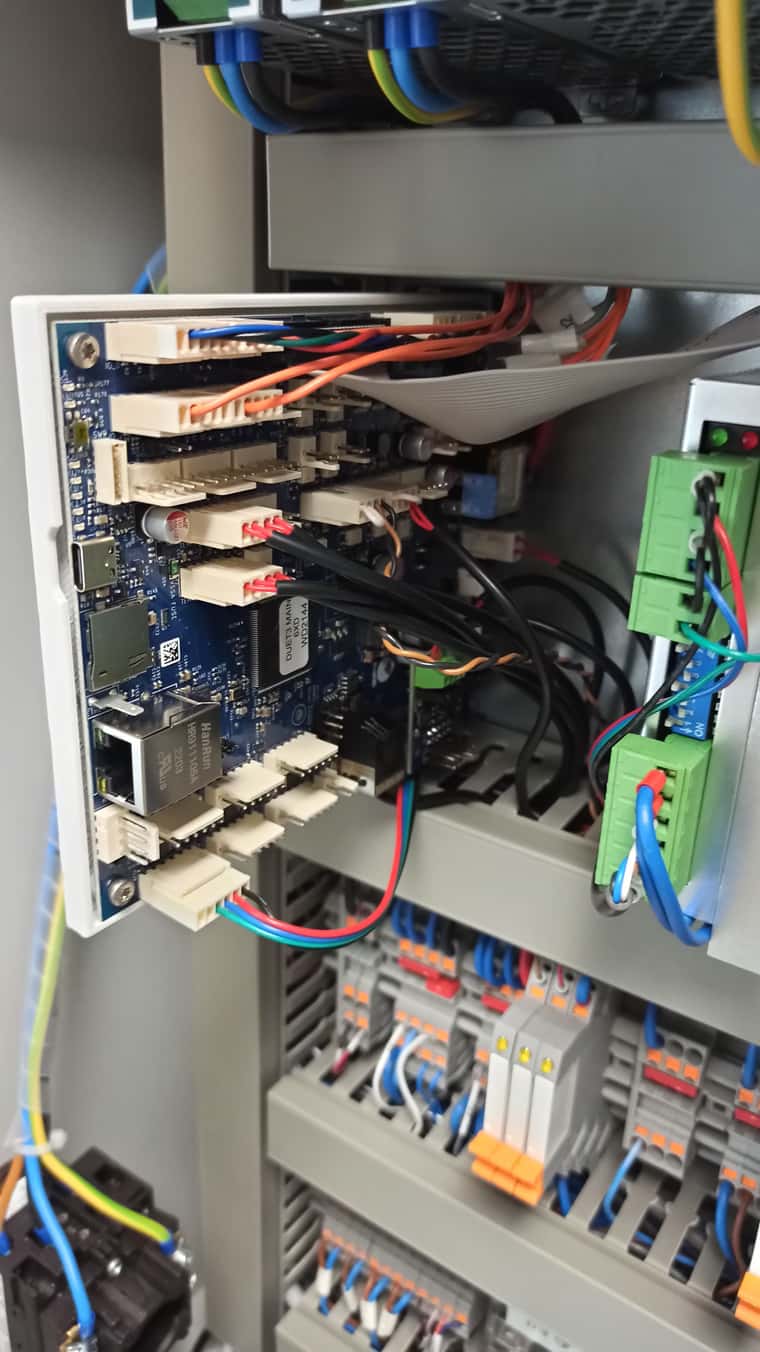
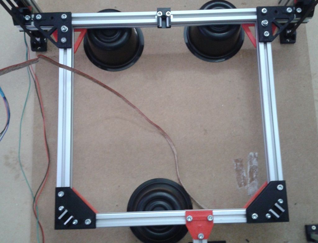
Jumping right in to post some update pictures of the current state, it's pretty close to the final wiring ( yuck!)
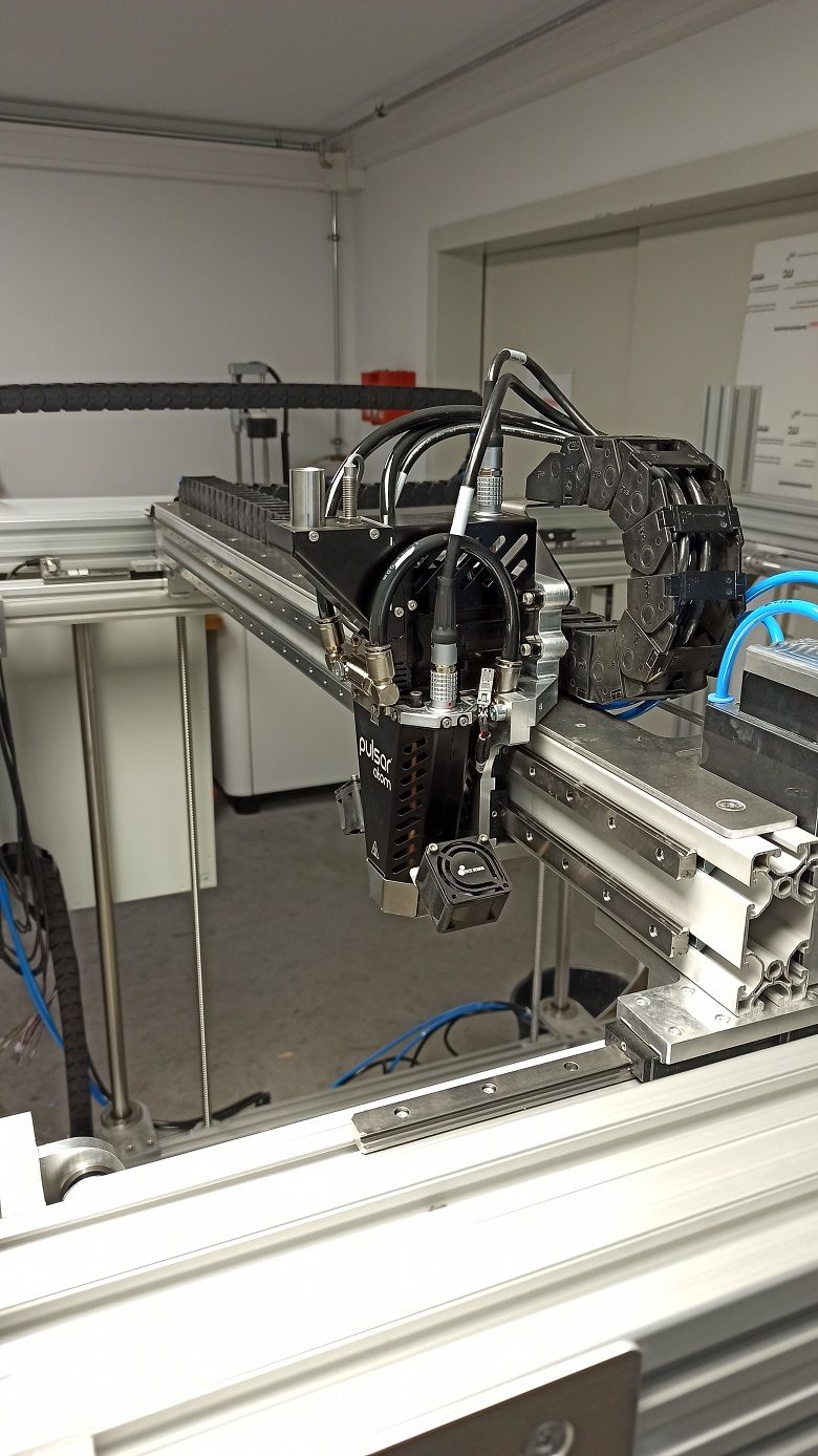
Does anybody know how far the Duet inductive bed probe does travel in terms of distance to a metal surface?
-
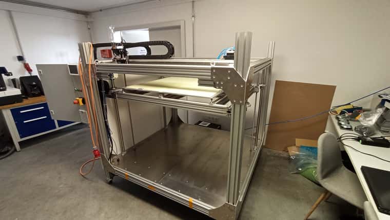
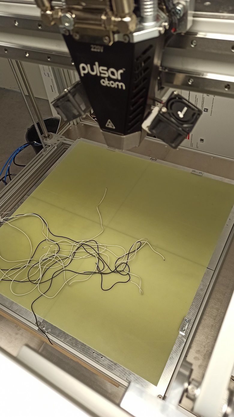
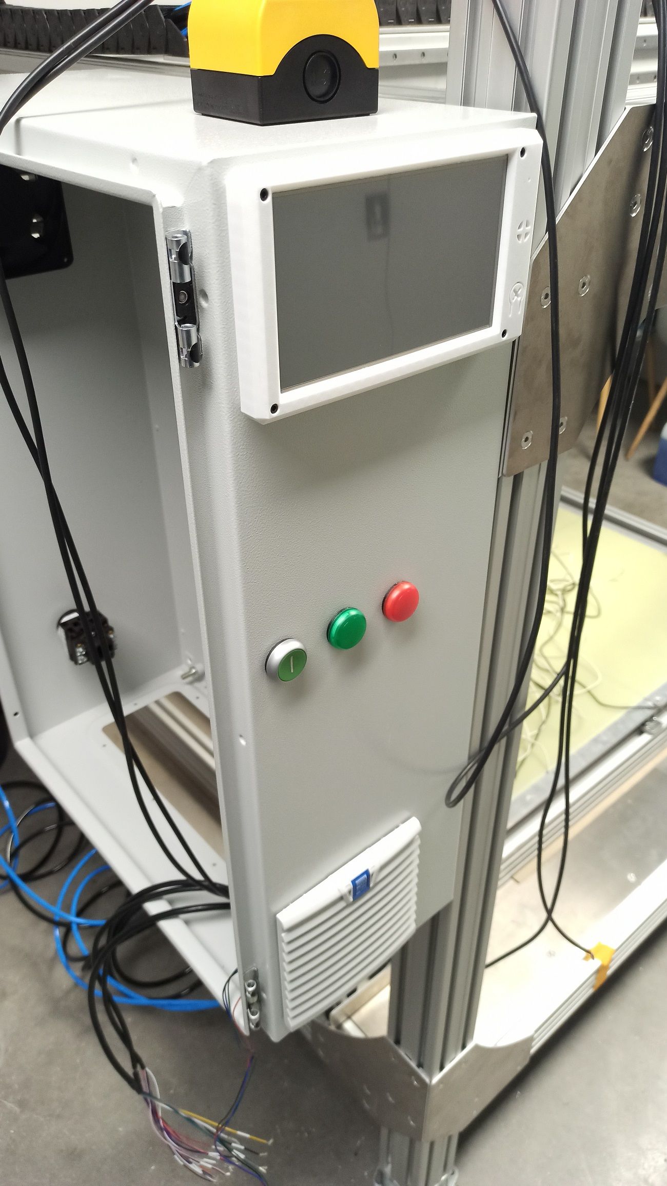
Status update,
The machine is now up and running, yet not completed but good for now running some experiments
Test move:
https://youtube.com/shorts/3CKMNepaWuw?si=1G-3YxQf6VK5LicsProbing:
https://youtube.com/shorts/EADCz_VwGls?si=ZgHFzYnbh_czCJaQ