Wiring a Duet 3 Scanning Z-Probe v1.0 to a Toolboard v1.3
-
This post is deleted! -
@gloomyandy Thank you for the information. I am not that great at wiring things at my age... But, I will take a closer look at the possible replacement for the probe and maybe tool board by the looks of it. Just was hoping to stay with all Duet on this build. But, it seems that is not possible due to design oversight. Thanks for the link.

-
@jay_s_uk Yeah, thanks. I figured that would be the case. Running a bunch of CAN wires from the hotend seems like such a waste. One for the Toolboard and another for the Z-Probe. I hope that will be it... because the lack of my due diligence seems to be costing me in the end. Welp! I guess I will have to either run multiple CAN lines to the distribution board or just configure an inductive probe and attach that to the tool board... and on a 500x500mm heat bed that will take a while. lol Well thank you for your help it means a lot.
-
@WOPR73 yeah, the toolboard only has the "in" if you will for the CAN to control the rest of the items connected to it. the board doesnt have an "out" for additional CAN connections. The distribution board does have 3 more CAN connections. So, there is that if you do not mind running multiple CAN wires from the same location back to the distro board.
-
@WOPR73 You do not need to run multiple CAN wires to the toolhead nor do you need to replace the boards you already have. Please re-read the posts above. The solution provided by jay offers the simplest solution and requires just 4 wires (two CAN wires plus power) from your mainboard to the 1LC and then four wires from the 1LC to the SZP.
The second solution I provided will require the standard distribution board wiring to the 1LC (so 4 CAN wires in a loop plus power) then an additional 4 wires (two can plus power) wires to the SZP the CAN wires to the SZP would be spliced on to the CAN wires close to the 1LC.
I don't have access to a drawing program at the moment to provide a diagram of the above, perhams some that does can provide something that will help explain the proposed solutions.
-
@WOPR73 said in Wiring a Duet 3 Scanning Z-Probe v1.0 to a Toolboard v1.3:
@WOPR73 yeah, the toolboard only has the "in" if you will for the CAN to control the rest of the items connected to it. the board doesnt have an "out" for additional CAN connections. The distribution board does have 3 more CAN connections. So, there is that if you do not mind running multiple CAN wires from the same location back to the distro board.
The 1LC toolboard has two pairs of can wires to allow the CANBUS to be looped through it
 <img src="blob:chrome-untrusted://media-app/4cf83316-03f3-41a1-8da0-dcd169dcd8fb" alt="Screenshot 2024-04-13 08.46.42.png"/>
These can also be used as described by Jay above to connect to the SZP board.
-
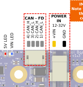
@gloomyandy So if I understand this correctly. From the Distribution Board run CAN and Power to the 1LC, But only use 1) CAN_L and 2) CAN_H to control the 1LC. Then use 3) CAN_L and 4) CAN_H from the Distribution Board for connecting to the SZP and pull +v5 and GND from the 1LC. Correct? Is this because 3) CAN_L and 4) CAN_H are not use due to 1LC not having a CAN_OUT?
-
@WOPR73 said in Wiring a Duet 3 Scanning Z-Probe v1.0 to a Toolboard v1.3:
@gloomyandy So if I understand this correctly. From the Distribution Board run CAN and Power to the 1LC, But only use 1) CAN_L and 2) CAN_H to control the 1LC. Then use 3) CAN_L and 4) CAN_H from the Distribution Board for connecting to the SZP and pull +v5 and GND from the 1LC. Correct? Is this because 3) CAN_L and 4) CAN_H are not use due to 1LC not having a CAN_OUT?
No, like this.
- From the distribution board run a single pair of CAN wires from CAN1_L and CAN1_H (see https://docs.duet3d.com/duet_boards/duet_3_can_expansion/duet_3_tool_distribution_board_v0.5_wiring.png) to one pair of the the tool board CAN_L and CAN_H connections
- Connect the other pair of tool board CAN_L and CAN_H connections to the CAN_L and CAN_H connections of the SZP
- Connect +5V and GND of the tool board IO0 connector to +5V and GND on the SZP.
- Make sure that the termination resistor is enabled on the SZP, and disabled on the tool board.
Duet WiFi hardware designer and firmware engineer
Please do not ask me for Duet support via PM or email, use the forum
http://www.escher3d.com, https://miscsolutions.wordpress.com -
@dc42 Does the OP need to remove the optional terminator from the distribution board in this configuration?
-
@gloomyandy the CAN bus won't proceed beyond the first of the four tool outputs on the distribution board if it is wired like this, so it doesn't matter whether the termination jumper is fitted or not,
-
This post is deleted! -
@dc42 So, I can do all of this from Tool 0 CAN-FD on the distro board(remove jumpers). I am just splitting the two pairs of CAN, One to the Toolboard and the other pair to SZP.
-
@WOPR73 yes that's correct. The CAN bus will run from the main board to the distribution board, from that to the tool board, and from the tool board to the SZP. It will be terminated with 120 ohm resistors at both ends i.e. at the Duet 3 Mini and the SZP.
Duet WiFi hardware designer and firmware engineer
Please do not ask me for Duet support via PM or email, use the forum
http://www.escher3d.com, https://miscsolutions.wordpress.com -
@WOPR73 wait. what? 120 ohm resistors at both ends? Duet 3 mini? Mini what?
-
@WOPR73 I think you have a 6HC, not a Mini 5+. The mainboard has built in 120ohm resistor for termination, so you don't have to worry about terminating that end. At the other end of the CAN bus, the SZP provides the termination.
Ian
Bed-slinger - Mini5+ WiFi/1LC | RRP Fisher v1 - D2 WiFi | Polargraph - D2 WiFi | TronXY X5S - 6HC/Roto | CNC router - 6HC | Tractus3D T1250 - D2 Eth
-
@droftarts yeah, I have a 6HC. I bought the distribution board after I saw that in one of the documents stating I would have to use a resistor in able to connect them. One would think that Duet would have some kind of unified standard of conformity for the connection between components that they have created. I am new to wiring up my own 3D printer and have to research a lot of this stuff to make sure I don't make a mistake. This is by no means close to plug-and-play. Welp, lesson learned I guess.
The Tool Distribution Board came with 4 premade CAN wires. I am not sure what would be easier or cleaner.
- Using 2 premade CAN wires running back to the Tool Distribution board. One from the SZP and the other one from the 1LC, both being plugged in at the Distribution board.
or - trying to undo one pair of the wires on the 1LC CAN connection and run it to the SZP.
Would have been nice to just have a CAN out on the 1LC. Either way I still need to take the 5v+ and GND from the tool board so it wont be clean looking. I really wish I would have seen this coming.

Any thoughts?
- Using 2 premade CAN wires running back to the Tool Distribution board. One from the SZP and the other one from the 1LC, both being plugged in at the Distribution board.
-
@dc42 Sorry, But I have a 6HC and a Tool Distribution board. So, I should not need the resistor. With splitting the CAN pair from the Distribution board and one pair going to the 1LC and the other pair going to the SZP. Still unable to M115 or M122 to either. And yes I do have the jumper removed on the distribution board. Using the same connection on the 24v power supply that is being used on the 6HC. Then running power from the distribution board to the 1LC and a blue light is on. But, no response.
4/25/2024, 10:41:36 PM M122 B121
CAN response timeout: board 121, req type 6024, RID 84/25/2024, 10:41:11 PM M115 B121
CAN response timeout: board 121, req type 6024, RID 7i've tried B20, B21 B10, etc; as referred to in some of the duet documents. I went back to the basics and I'm just using the 6HC, Tool Distribution Board and 1LC with supplied CAN cables that came with the Tool Distribution Board. Plus a default config from the RFF config tool.
I was able to upgrade to latest:
Duet Web Control 3.5.1
Panel Due 7i 3.4.1 -
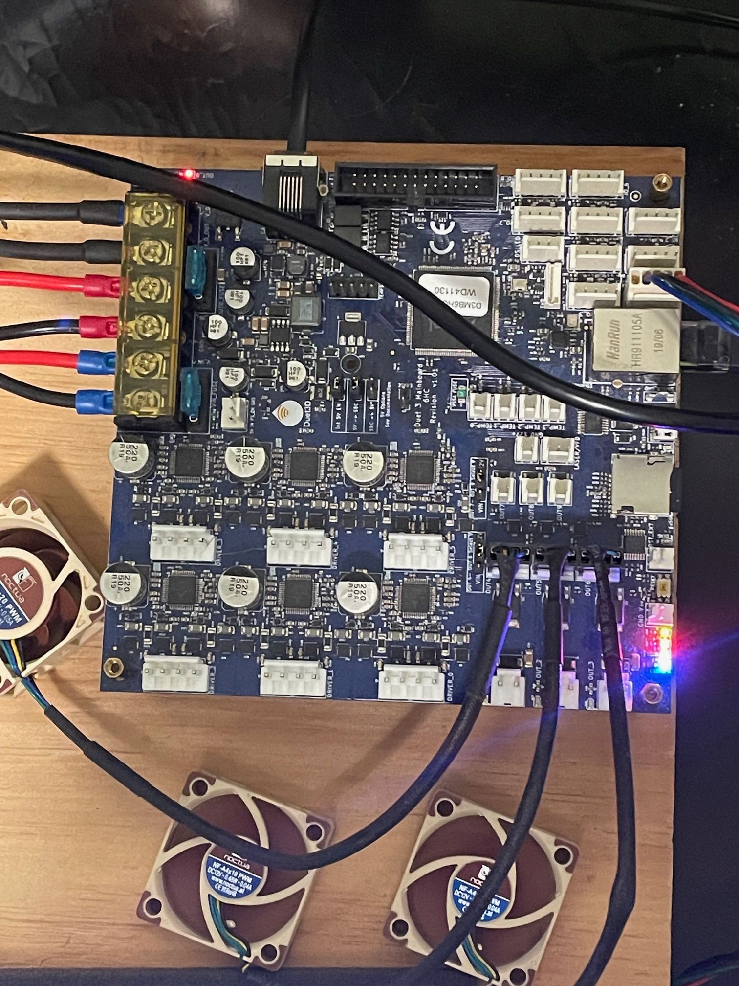
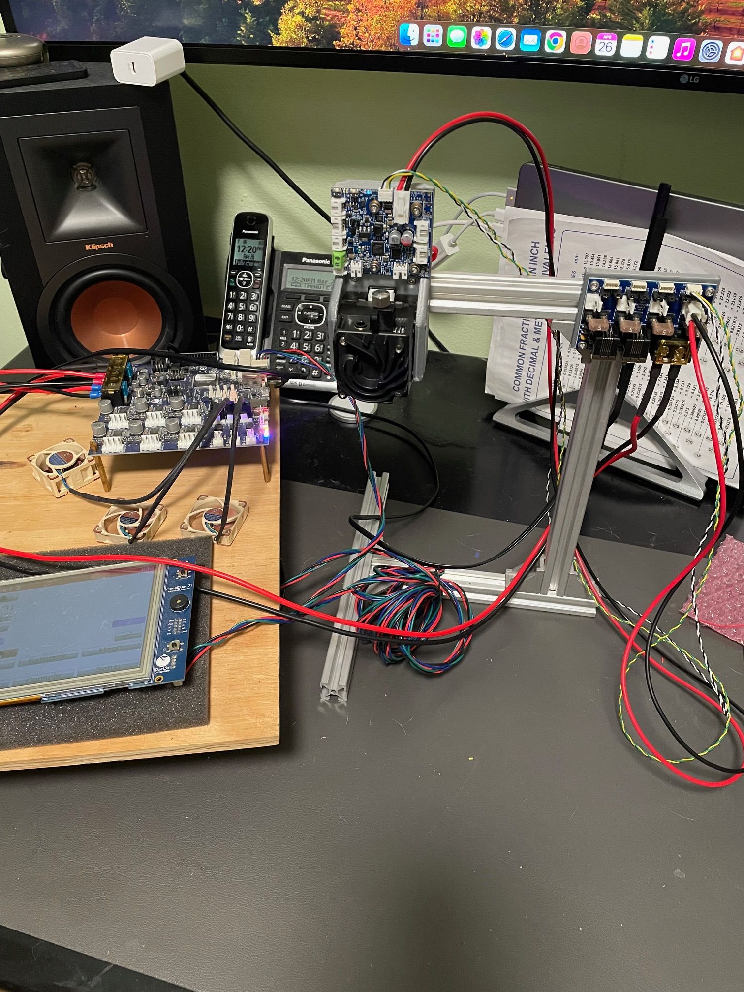
Can you share some photos of your wiring setup?
-
@Phaedrux Sure, Not the best lighting... but, it should do. I have just tried stand alone without a Pi4 and still can not talk to the 1LC.
4/26/2024, 12:05:11 AM M122 B121
CAN response timeout: board 121, req type 6024, RID 6
4/26/2024, 12:05:07 AM M122 B120
CAN response timeout: board 120, req type 6024, RID 5
4/26/2024, 12:05:01 AM M115 B120
CAN response timeout: board 120, req type 6024, RID 4
4/26/2024, 12:04:50 AM M115 B121
CAN response timeout: board 121, req type 6024, RID 3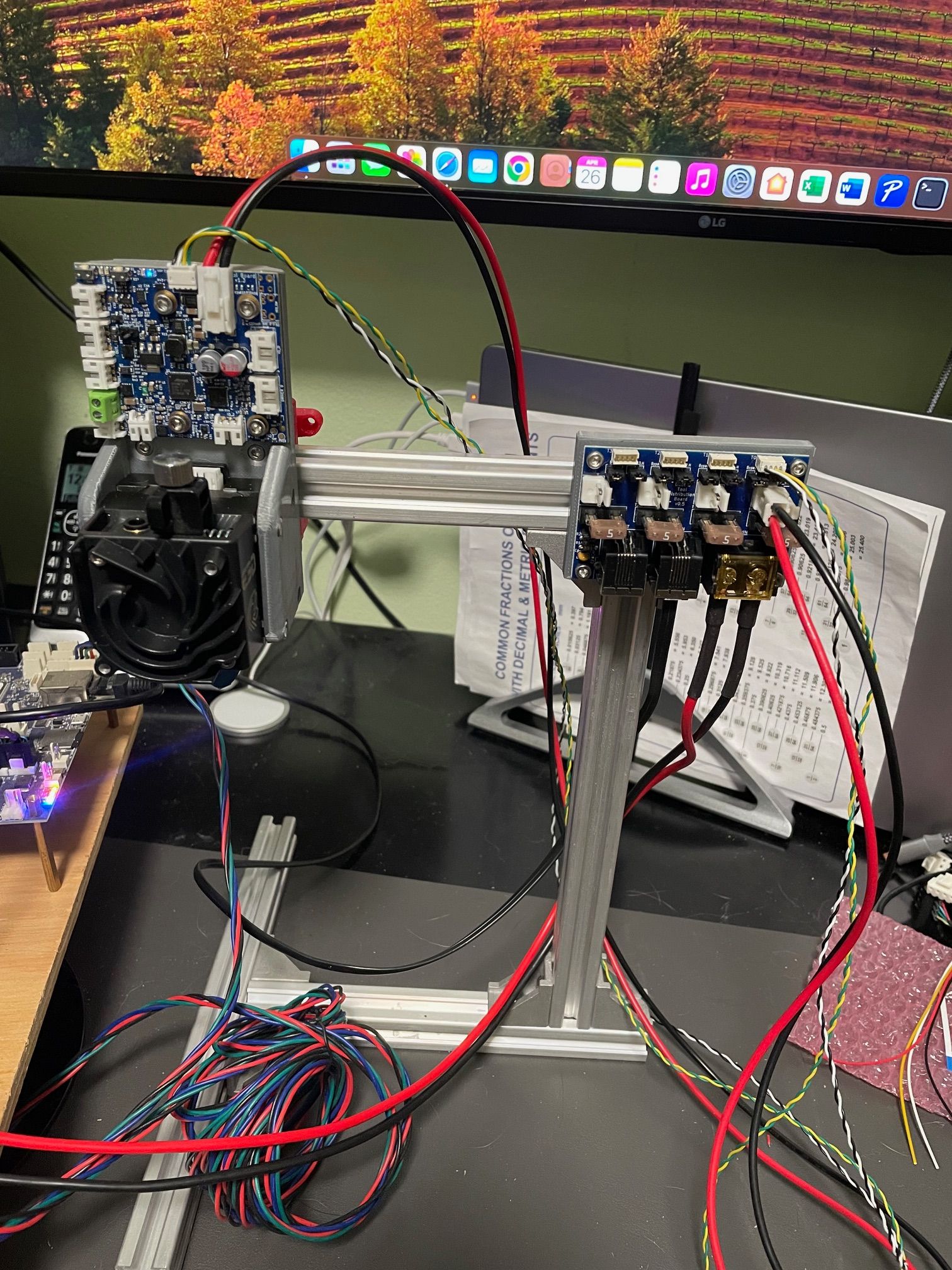
-
@WOPR73 from your pictures, I can see that you need to remove the bypass jumpers on the distribution board under the 1LC connection.
Are you having problems connecting to the 1LC on its own? Have you ever been able to connect? I can’t see the SZP wired in in your pictures, looks like just the 1LC is wired in at the moment to the distribution board. In this configuration (I can’t see the SZP connected) the termination jumper should be fitted on the distribution board too.
If you still can’t connect, check that your CAN cable from 6HC to distribution board is correct; flat cables like you have are often wired incorrectly for CAN, see https://docs.duet3d.com/en/User_manual/Machine_configuration/CAN_connection#example-of-a-good-cable
Then check your wiring; that the wire from the distribution board CAN_H goes to CAN_H on the toolboard, and so on.
As others have said, if you’re only ever going to run a 1LC and SZP, the distribution board is a bit redundant. You can take two wires from the 6HC (to the 1LC CAN in, then two wires from the 1LC CAN out to the SZP. Set the SZP to provide termination.
If you plan to add more tools, the distribution board makes sense, though the tool with the SZP will still need to be the last on the CAN bus.
Ian
Bed-slinger - Mini5+ WiFi/1LC | RRP Fisher v1 - D2 WiFi | Polargraph - D2 WiFi | TronXY X5S - 6HC/Roto | CNC router - 6HC | Tractus3D T1250 - D2 Eth