Problems from the second layer to the 7th layer
-
@oliof said in Problems from the second layer to the 7th layer:
@carlinicompetizione A raspberry pi does not help here. There is some chance that this is not a software, but a hardware issue, i.e. the mechanism raising the nozzle (or lowering the bed) may be binding until it overcomes the early layers.
You could try commanding the printer without issuing a full print, doing moves with the G0 and G1 commands after homing, to see how things behave.
I would like to know if there is a possible solution to this problem that the system has that disregards the first layers?, the printer is industrial, and I have already spent too much time making it work with this Duet 3D 6HC card. I really need a solution, otherwise I have to change my motherboard to another brand that is less problematic and can print without so much hassle.
-
@carlinicompetizione If we knew the answer to this issue, we would have told you already! We have to find out the information to try and solve it from you, so any information you can give us helps.
it starts printing at Z=2 9 this value is the baby step
I think you're saying that you are using 2mm of baby stepping. I'd guess this is the issue, and it's probably because you have not set the Z probe Z offset correctly. Baby stepping usually only needs to be a small adjustment, maybe +/- half a layer height. Much more than that, yes, odd things are likely to happen.
Please set the Z probe Z offset again. Currently the X and Y offsets are set to 0 as well, so set them to. You're using a BLTouch I think, so there should definitely be an X, Y and Z offset. Your current probe offset is:
G31 P500 Y0; definir valor de disparo da sonda Z, deslocamento e altura de disparo
G31 P500 X0 Z0.85 ; definir valor de disparo da sonda Z, deslocamento e altura de disparo
You can put this on one like together, like this:
G31 P500 X0 Y0 Z0.85 ; definir valor de disparo da sonda Z, deslocamento e altura de disparoFor setting Z probe X, Y and Z offset, see https://docs.duet3d.com/en/User_manual/Connecting_hardware/Z_probe_testing
Ian
Bed-slinger - Mini5+ WiFi/1LC | RRP Fisher v1 - D2 WiFi | Polargraph - D2 WiFi | TronXY X5S - 6HC/Roto | CNC router - 6HC | Tractus3D T1250 - D2 Eth
-
I believe we have discovered the problem. I started to slow down
changing microsteps from 16 to 8 and Z began to move as programmed in the slicer. Without being satisfied with the result, I went back to 16 microsteps and lowered the instantaneous on Z by approximately 30%. Then I managed to print a piece with a higher quality than what I had until then. Even so, the first to second layer is not respecting the programmed distance.
EX: the first layer starts at Z=0.40mm (this height is correct according to the baby step, also from 0.40mm or less. In the slicer, a layer height of 0.3mm was determined, so the second layer would start with Z=0.7mm , but it was only for 0.51mm, so I did a manual intervention just to understand if the next layers would maintain this flaw (I paused the printing and lowered the table manually to complete the 0.19 mm) when the second layer was finished and the third started. the value was already correct Z=0.81 mm. It seems to me like a bug in the firmware, it doesn't make sense to do that. -
@carlinicompetizione Did you try any of the things I suggested?
- calibrate your Z probe offset - https://docs.duet3d.com/en/User_manual/Connecting_hardware/Z_probe_testing
- try a print without baby stepping - set
G92 Z0with the nozzle just touching the bed before printing, don't home Z at the beginning of the print - try a print without mesh bed compensation
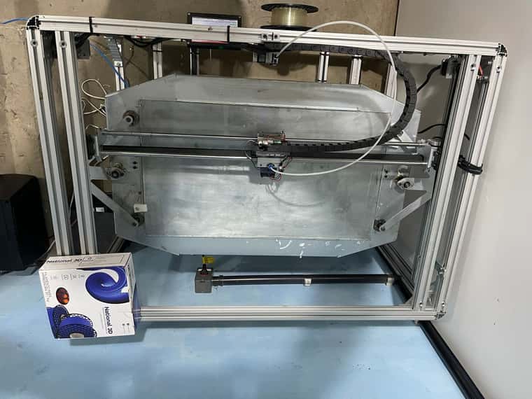
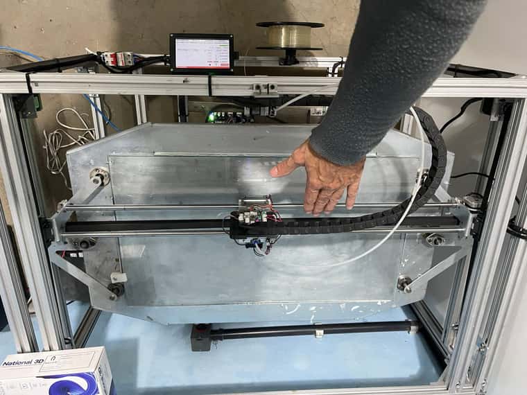
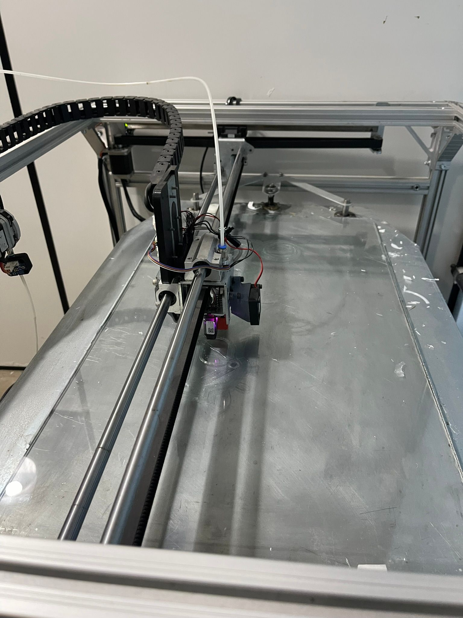
And one more thing to try: yes, your Z jerk looks high to me, and so does your acceleration and maximum speed for Z, especially for the steps per mm on Z. I don't know the layout of your machine, how heavy the bed is, or even if the bed moves in Z, or if your gantry moves in Z. So the values you have might be okay, but might not be. Maybe post a picture of your printer so we can get a better idea of the size. For example, I have a bed slinger with 200x200mm bed and 2mm lead M8 leadscrews, and can only move them this fast before skipping (though they are quite small NEMA 17 motors):
M92 Z800  ; set steps per mm
M566 Z12  ; set maximum instantaneous speed changes (mm/min)
M203 Z600 ; set maximum speeds (mm/min)
M201 Z20  ; set accelerations (mm/s^2)
Yours were set as:
M92 Z1650.50
M566 Z300.00
M203 Z1000.00
M201 Z250.00
Though I'm not sure why your settings would not work to start with, and then work okay at later layers. If you can share a full Gcode file, that may help.
I'd suggest setting low values for jerk, acceleration and maximum speed (ie like mine), and check if movement is correct. If it is, you can then increase them until you find the limit.
Ian
Bed-slinger - Mini5+ WiFi/1LC | RRP Fisher v1 - D2 WiFi | Polargraph - D2 WiFi | TronXY X5S - 6HC/Roto | CNC router - 6HC | Tractus3D T1250 - D2 Eth
-
-
-
I am wondering if commas and decimals are interchangeable in config.g.
Your M566 uses commas and the rest use decimals.
@carlinicompetizione said in Problems from the second layer to the 7th layer:
M566 X500,00 Y500,00 Z300,00 E1200,00 ; definir alterações instantâneas máximas de velocidade (mm/min)
M203 X3000.00 Y3000.00 Z1000.00 E1200.00 ; definir velocidades máximas (mm/min)
M201 X500.00 Y500.00 Z250.00 E1200.00 ; definir acelerações (mm/s^2) -
@tas
In the config.g in the file everything is with a dot, but I'll check, you'll see that something typing is getting in the way too -
@droftarts
In these days I made several impressions to fine-tune the resolution that until then I could not make due to so much instability of operation. The last impressions with a 0.8 beak are getting good. using simplify3D that seems somewhat limited compared to Cura.
Even so, when starting the second layer, the table does not go down to the correct value. When it goes to third, it works normally. It's very strange. It doesn't make any sense. I lowered the Jerk values a lot from 500mm/min to 300mm/min. The z was at 110 I went to 60mm/min, but I will lower it more to see if it solves the problem of the second layer, it is interesting because it goes down only half the value stipulated by the slicer. But only in this layer that does this. Then take off cute. -
Sounds like mechanical binding on the z axis. Are you able to turn the z axis by hand and feel for change in resistance?
-
I found some settings that really helped it work, but I believe that activating the M208 was the big point, because until then nothing was working, as if the machine didn't have a reference point, all the changes made up until now had already been done before but without realizing that the 208 was disabled. So I would like to contribute with the config.g file as it is and everything works.
; Configuration file for Duet 3 MB 6HC (firmware version 3.3)
; executed by the firmware on start-up
;
; generated by RepRapFirmware Configuration Tool v3.3.16 on Sat Jun 24 2023 18:49:15 GMT-0300 (Horário Padrão de Brasília); General preferences
G90 ; send absolute coordinates...
M83 ; but relative extruder moves
M550 P"UNO Print" ; set printer name; Wait a moment for the CAN expansion boards to start
G4 S2; Network
M552 P0.0.0.0 S1 ; enable network and acquire dynamic address via DHCP
M586 P0 S1 ; enable HTTP
M586 P1 S1 ; disable FTP
M586 P2 S0 ; disable Telnet; Drives
M569 P0.0 S1 ; physical drive 0.0 goes forwards
M569 P0.1 S0 ; physical drive 0.1 goes forwards
M569 P0.2 S0 ; physical drive 0.2 goes forwards
M569 P0.3 S1 ; physical drive 0.3 goes forwards
M569 P0.4 S0 ; physical drive 0.4 goes forwards
M569 P0.5 S0 ; physical drive 0.5 goes forwards
M584 X0.1 Y0.2:0.3 Z0.4:0.5 E0.0 ; set drive mapping
M350 X16 Y16 Z16 E16 I1 ; configure microstepping with interpolation
M92 X67.00 Y67.00 Z1650.50 E370.00 ; set steps per mm
M566 X300.00 Y300.00 Z15.00 E5500.00 ; set maximum instantaneous speed changes (mm/min)
M203 X3500.00 Y3500.00 Z1100.00 E5500.00 ; set maximum speeds (mm/min)
M201 X300.00 Y300.00 Z180.00 E100.00 ; set accelerations (mm/s^2)
M906 X1680 Y1600 Z1600 E920 I90 ; set motor currents (mA) and motor idle factor in per cent
M84 S75 ; Set idle timeout; Axis Limits
M208 X0 Y0 Z0 S1 ; set axis minima
M208 X700 Y400 Z400 S0 ; set axis maxima; Endstops
M574 X1 S1 P"121.io2.in" ; configure switch-type (e.g. microswitch) endstop for low end on X via pin io0.in
M574 Y1 S1 P"io1.in+io2.in" ; configure switch-type (e.g. microswitch) endstop for low end on Y via pin io1.in+io2.in
M574 Z2 S1 P"io4.in+io5.in" ; configure switch-type (e.g. microswitch) endstop for low end on Y via pin io3.in+io4.in
M574 Z1 S2
;M574 X1 S1 P"121.io2.in" ; configure switch-type (e.g. microswitch) endstop for low end on X via pin io0.in
;M574 Y1 S1 P"io1.in+io2.in" ; configure switch-type (e.g. microswitch) endstop for low end on Y via pin io1.in+io2.in
;M574 Z1 S1 P"io3.in+io4.in" ; configure switch-type (e.g. microswitch) endstop for low end on Y via pin io3.in+io4.in
;M574 Z1 S2 ; configure Z-probe endstop for low end on Z
;M574 Z1 S1 P"io3.in+io4.in" ; configure endstop for high end on Z; Heaters
M308 S0 P"temp0" Y"pt1000" ; configure sensor 0 as PT1000 on pin temp0
M950 H0 C"out0" T0 ; create bed heater output on out0 and map it to sensor 0
M307 H0 B1 S1.00 ; enable bang-bang mode for the bed heater and set PWM limit
M140 H0 ; map heated bed to heater 0
M143 H0 S120 ; set temperature limit for heater 0 to 120C
M308 S1 P"121.temp0" Y"pt1000" ; configure sensor 1 as PT1000 on pin 121.temp0
M950 H1 C"121.out0" T1 ; create nozzle heater output on 121.out0 and map it to sensor 1
M307 H1 B0 S1.00 ; disable bang-bang mode for heater and set PWM limit
M143 H1 S280 ; set temperature limit for heater 1 to 280C; Tools
M563 P0 D0 H1 F0 ; define tool 0
G10 P0 X0 Y0 Z0 ; set tool 0 axis offsets
G10 P0 R0 S0 ; set initial tool 0 active and standby temperatures to 0C; Fans
M950 F0 C"121.out1" Q500 ; create fan 0 on pin 121.out1 and set its frequency
M106 P0 S0 H-1 ; set fan 0 value. Thermostatic control is turned off
M950 F1 C"121.out2" Q500 ; create fan 1 on pin 121.out2 and set its frequency
M106 P1 S1 H-1 ; set fan 1 value. Thermostatic control is turned off; Z-Probe
M950 S0 C"121.io0.out" ; Duet 3 MB6HC
M558 P9 C"121.io0.in" H5 F120 T6000 ; Duet 3 MB6HC
G31 P500 Y0 ; set Z probe trigger value, offset and trigger height
G31 P500 X0 Z0.65 ; set Z probe trigger value, offset and trigger height
M557 X125:650 Y50:350 S262.5:150 ; define mesh grid
;M374
;M374 P"HeightMap.csv"
;M375
;M375 P"HeightMap.csv" ; Salva o mapa da grid do autolevel
M376 H10 ; corrige a sobre extrusão na compensaão até 5%; Custom settings are not defined
M575 P1 S1 B57600
;M572 D0 S0.45 ; definir o avanço de pressão da extrusora 0 para 0,1 segundos; Miscellaneous
M501 ; load saved parameters from non-volatile memory
M911 S10 R11 P"M913 X0 Y0 G91 M83 G1 Z3 E-5 F1000" ; set voltage thresholds and actions to run on power loss
M950 D1 C"spi.cs0+spi.cs2" ; PanelDue
M591 D0 P3 C"io6.in" S1 R5:170 ; filament monitor connected to io6.in -
@carlinicompetizione said in Problems from the second layer to the 7th layer:
;M208 X0 Y0 Z0 S1 ; set axis minima
why was it commented out in the first place?
-
@carlinicompetizione I don't know why leaving out the M208 command would cause this issue, because if it is missing, the firmware sets a default of 0 (for minimum) and/or 200 (for maximum) in each axis. eg if I comment out all M208 commands in my config.g, then send M208 after a restart, it reports:
M208
Axis limits (mm) X0.0:200.0, Y0.0:200.0, Z0.0:200.0
Ian