Drive standard LEDs. What is the max current rating of IO pins?
-
Hi everyone,
I'm working on wiring a power button on my Voron printer, powered by a Duet 3 6HC 1.01 revision.
The power button is one of those anti-vandal switches, but has 3 independent LEDs built-in (Red, Green, Blue).
Being an AliExpress product, I had to measure the forward voltage of the LEDs with my multimeter and it reads 1.82V for Red, 2.32V for Green and 2.56V for Blue.As its essentially individual LEDs, I can't use the dotstar connector and since I have plenty of free IO, I was considering using the IO at 5V and applying inline resistors for each LED.
I plan in limiting the LEDs to 15mA each.How much current can each IO tolerate? I assume it's not limited by the 5V 3A max rail is it?
Lastly, the switch will be having 230V AC going thru the switch pins, what would be the best way to protect the Duet 3 in case the switch goes bad? Would diodes be enough?
(Please note that the 230V AC will be used to drive a relay)Thank you.
-
@Ralms said in Drive standard LEDs. What is the max current rating of IO pins?:
How much current can each IO tolerate? I assume it's not limited by the 5V 3A max rail is it?
Yes, it is. See https://docs.duet3d.com/Duet3D_hardware/Duet_3_family/Duet_3_Mainboard_6HC_Hardware_Overview#operating-limits
The 6HC v1.01 has a current limit of 3A for the total current on 5V and 3.3v (v1.02 and later is limited to 800mA due to a change in voltage regulator). I think the pins on the IO headers are good for conducting 1A. So I don't think there is any problem wiring the LEDs to the IO headers, as they are drawing only 15mA each.
@Ralms said in Drive standard LEDs. What is the max current rating of IO pins?:
Lastly, the switch will be having 230V AC going thru the switch pins, what would be the best way to protect the Duet 3 in case the switch goes bad? Would diodes be enough?
Unfortunately, I don't know enough to advise you on that! Though you say the LEDs are 'independent', so if they are electrically isolated from the mains voltage, I'm not sure how the switch going bad would cause a short to this wiring. Maybe I lack enough imagination for types of 'going bad'!
Ian
Bed-slinger - Mini5+ WiFi/1LC | RRP Fisher v1 - D2 WiFi | Polargraph - D2 WiFi | TronXY X5S - 6HC/Roto | CNC router - 6HC | Tractus3D T1250 - D2 Eth
-
@droftarts said in Drive standard LEDs. What is the max current rating of IO pins?:
I'm not sure how the switch going bad would cause a short to this wiring. Maybe I lack enough imagination for types of 'going bad'!
Ian
The switch is like this:
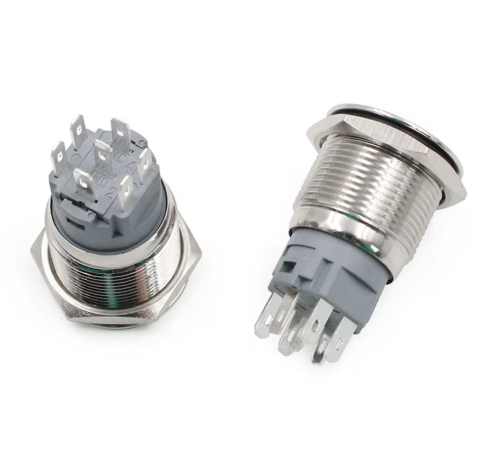
What I meant with the LEDs being independent was to distinguish from more modern addressable RGB LEDs.
All 3 LEDs are built-in in the button, they share a common ground and than have their respective pin.
(the 4 side pins are for the LEDs, the ones numbered.)My concerns in protecting the LED circuit from a potential short from the AC pins are 2 fold:
- Undisclosed dielectric strength from the seller (typical AliExpress product).
- Possibility of the switch melting for some reason, even though will be carrying around 10mA at 230V AC, resulting in a short due to switch proximity.
Either way, this concern is not specific to duet and maybe its just me being overly cautious.
I will figure it out and if anything ask for recommendations on an electronics focused forum")
Thank you
-
@Ralms said in Drive standard LEDs. What is the max current rating of IO pins?:
All 3 LEDs are built-in in the button, they share a common ground
Maybe you get more trouble from the fact that they share GND?
AFAIK all MOSFet IO-ports on Duet boards switch to GND and that wouldn't work for you. -
@o_lampe that's correct. Some sort of relay would have to be used to switch the +ve side
-
@jay_s_uk I was about to edit my reply, because maybe the TS wants to use IO pins from the MCU directly?
In that case I wouldn't draw more than 2mA from each pin. -
@o_lampe @Ralms the MCU pins that drive the IO_OUT pins on the 6HC are each rated to 4mA or more. There is a 470 ohm resistor between the MCU pin and the IO_OUT pin on the connector. So it's OK to connect an LED directly between an IO_OUT in and ground, because given the volage drop of the LED you won't get more than 4mA flowing. However, you may not get enough current to light the LED sufficiently.
When wired like this (or with the LEDs connected directly t the Duet in any other way), a short circuit between the LED pins and the 230V pins on the switch would destroy the Duet immediately.
Duet WiFi hardware designer and firmware engineer
Please do not ask me for Duet support via PM or email, use the forum
http://www.escher3d.com, https://miscsolutions.wordpress.com -
@dc42 said in Drive standard LEDs. What is the max current rating of IO pins?:
@o_lampe @Ralms the MCU pins that drive the IO_OUT pins on the 6HC are each rated to 4mA or more. There is a 470 ohm resistor between the MCU pin and the IO_OUT pin on the connector. So it's OK to connect an LED directly between an IO_OUT in and ground, because given the volage drop of the LED you won't get more than 4mA flowing. However, you may not get enough current to light the LED sufficiently.
When wired like this (or with the LEDs connected directly t the Duet in any other way), a short circuit between the LED pins and the 230V pins on the switch would destroy the Duet immediately.
Thank you for the clarification.
Yes, I'm perfectly aware that 230V would kill the duet, hence trying to be really careful

After some research, I've decided that I will use a daughter PCB just to deal with the switch, where the relay will be activated using something like a TRIAC Optocoupler, completely isolating AC out of the switch.
The reason I was trying to avoid this approach, was to be able to have the switch control the main power relay, without needing a second lower power DC power supply (mostly to lower standby consumption), but it would just be too risky.
-