Duet3D Logo Duet3D
    • Tags
    • Documentation
    • Order
    • Register
    • Login
    1. Home
    2. Ralms
    • Profile
    • Following 0
    • Followers 0
    • Topics 7
    • Posts 31
    • Best 1
    • Controversial 0
    • Groups 0

    Ralms

    @Ralms

    1
    Reputation
    3
    Profile views
    31
    Posts
    0
    Followers
    0
    Following
    Joined Last Online

    Ralms Unfollow Follow

    Best posts made by Ralms

    • RE: [Solved]Prevent docking/undocking of probe during multiple G30

      @jay_s_uk said in Prevent docking and undocking of probe during multiple G30 Pn:

      @Ralms call M401 to undock the probe and then do all your probing routines. That should prevent it docking it between.
      Then M402 at the end

      That did the trick.
      Thank you!

      Need to look into submitting some documentation improvements after finishing coding the printer lol

      posted in Tuning and tweaking
      Ralmsundefined
      Ralms

    Latest posts made by Ralms

    • RE: Drive standard LEDs. What is the max current rating of IO pins?

      @dc42 said in Drive standard LEDs. What is the max current rating of IO pins?:

      @o_lampe @Ralms the MCU pins that drive the IO_OUT pins on the 6HC are each rated to 4mA or more. There is a 470 ohm resistor between the MCU pin and the IO_OUT pin on the connector. So it's OK to connect an LED directly between an IO_OUT in and ground, because given the volage drop of the LED you won't get more than 4mA flowing. However, you may not get enough current to light the LED sufficiently.

      When wired like this (or with the LEDs connected directly t the Duet in any other way), a short circuit between the LED pins and the 230V pins on the switch would destroy the Duet immediately.

      Thank you for the clarification.

      Yes, I'm perfectly aware that 230V would kill the duet, hence trying to be really careful 😄

      After some research, I've decided that I will use a daughter PCB just to deal with the switch, where the relay will be activated using something like a TRIAC Optocoupler, completely isolating AC out of the switch.

      The reason I was trying to avoid this approach, was to be able to have the switch control the main power relay, without needing a second lower power DC power supply (mostly to lower standby consumption), but it would just be too risky.

      posted in Duet Hardware and wiring
      Ralmsundefined
      Ralms
    • RE: Drive standard LEDs. What is the max current rating of IO pins?

      @droftarts said in Drive standard LEDs. What is the max current rating of IO pins?:

      I'm not sure how the switch going bad would cause a short to this wiring. Maybe I lack enough imagination for types of 'going bad'!

      Ian

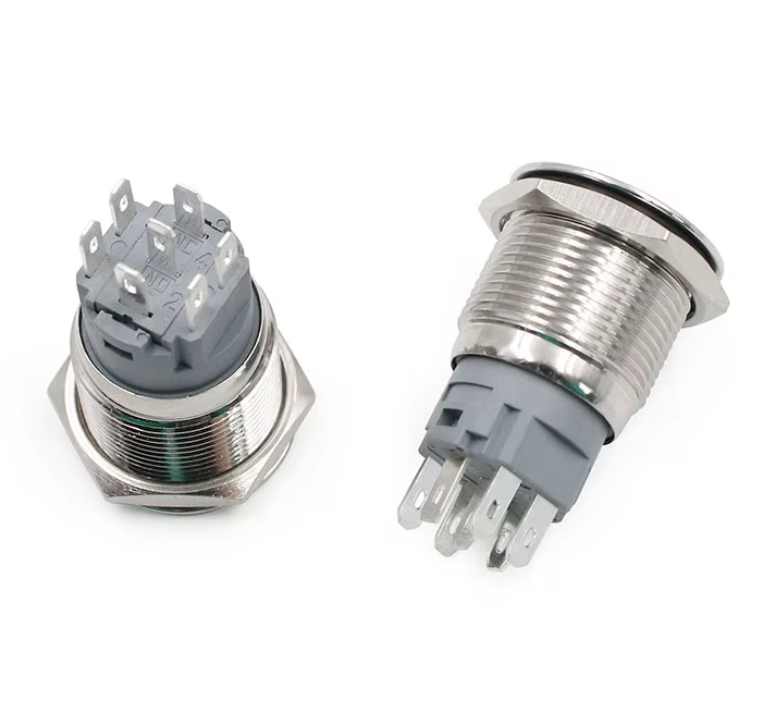
      The switch is like this:

      bbac1468-942f-40c8-9e96-c00de733e10e-image.png

      What I meant with the LEDs being independent was to distinguish from more modern addressable RGB LEDs.
      All 3 LEDs are built-in in the button, they share a common ground and than have their respective pin.
      (the 4 side pins are for the LEDs, the ones numbered.)

      My concerns in protecting the LED circuit from a potential short from the AC pins are 2 fold:

      • Undisclosed dielectric strength from the seller (typical AliExpress product).
      • Possibility of the switch melting for some reason, even though will be carrying around 10mA at 230V AC, resulting in a short due to switch proximity.

      Either way, this concern is not specific to duet and maybe its just me being overly cautious.
      I will figure it out and if anything ask for recommendations on an electronics focused forum 🙂

      Thank you

      posted in Duet Hardware and wiring
      Ralmsundefined
      Ralms
    • Drive standard LEDs. What is the max current rating of IO pins?

      Hi everyone,

      I'm working on wiring a power button on my Voron printer, powered by a Duet 3 6HC 1.01 revision.

      The power button is one of those anti-vandal switches, but has 3 independent LEDs built-in (Red, Green, Blue).
      Being an AliExpress product, I had to measure the forward voltage of the LEDs with my multimeter and it reads 1.82V for Red, 2.32V for Green and 2.56V for Blue.

      As its essentially individual LEDs, I can't use the dotstar connector and since I have plenty of free IO, I was considering using the IO at 5V and applying inline resistors for each LED.
      I plan in limiting the LEDs to 15mA each.

      How much current can each IO tolerate? I assume it's not limited by the 5V 3A max rail is it?

      Lastly, the switch will be having 230V AC going thru the switch pins, what would be the best way to protect the Duet 3 in case the switch goes bad? Would diodes be enough?
      (Please note that the 230V AC will be used to drive a relay)

      Thank you.

      posted in Duet Hardware and wiring
      Ralmsundefined
      Ralms
    • RE: Using G30 S0 inside homez.g fails

      @engikeneer said in Using G30 S0 inside homez.g fails:

      @Ralms so basically, when you called G30 from console, Z was already homed, so the problematic G1 line to move an unhomed axis in your deployprobe.g wasn't an issue? But when calling homez.g with just a G30 in it, the z axis is marked as unhomed before deployprobe.g is called and hence you got the error. Your problematic command was to move z anyway so x and y don't come into it.

      My point is that I think the behaviour you're seeing there is fully expected and 100% explainable

      You miss understood.
      Z is never homed in any of the scenarios I've mentioned (doing Home Z in the UI or calling G30 in the console), only X and Y are.

      So yes, my G1 move in the deployprobe.g was a problem always as it was trying to move Z20.

      The issue I'm raising now, is that G30 will execute from the console, even if deployprobe.g fails, it just ignores it and that should never happen.

      posted in Tuning and tweaking
      Ralmsundefined
      Ralms
    • RE: Using G30 S0 inside homez.g fails

      @engikeneer said in Using G30 S0 inside homez.g fails:

      @Ralms note that when you call a homing file it first flags the axis as unhomed. My guess is when you did it from command line you had already homed the z axis?

      When calling from the console, is just doing G30.
      G30 only resets the Z axis and doesn't touch X or Y.
      And yes, before calling G30 from the console, I already have the X and Y homed and with the probe in place.

      posted in Tuning and tweaking
      Ralmsundefined
      Ralms
    • RE: [Solved]Prevent docking/undocking of probe during multiple G30

      @jay_s_uk said in Prevent docking and undocking of probe during multiple G30 Pn:

      @Ralms call M401 to undock the probe and then do all your probing routines. That should prevent it docking it between.
      Then M402 at the end

      That did the trick.
      Thank you!

      Need to look into submitting some documentation improvements after finishing coding the printer lol

      posted in Tuning and tweaking
      Ralmsundefined
      Ralms
    • [Solved]Prevent docking/undocking of probe during multiple G30

      Hi everyone,

      As I continue to program my printer, I've ran into a behavior which I wonder if there is an easy solution.

      Essentially, the printer is a Voron 2.4, which 4 independent Z motors and to level it, I call G30 4 times as per the documentation:

      Here is the bed.g

      G28 ; home
      G30 P0 X30 Y300 Z-99999 ; probe near a leadscrew
      G30 P1 X30 Y60 Z-99999 ; probe near a leadscrew
      G30 P2 X270 Y60 Z-99999 ; probe near a leadscrew
      G30 P3 X270 Y300 Z-99999 S4 ; probe near a leadscrew and calibrate 4 motors
      

      The probe is a Klicky probe, which is a switch type probe, but since connected to the 1LC is defined as type 8.
      It's set with:

      M558 P8 C"^121.io2.in" H5 F200:100 K0 T2000 
      

      To be clear, the calibration is working fine.
      However, the printer is calling deployprobe.gand retractprobe.g for every single G30 Pn call, which makes it walk back and forth a bunch of times unnecessarily.

      I know that I can essentially use empty deployprobe.gand retractprobe.g files and have my macros called when needed, but I'm trying to avoid this, to not run the risk of having G30 called and not having the probe.
      Is there any way flag G30 so it doesn't call deployprobe.gand retractprobe.g?
      Or something like the macro parameters that I can send to G30, where it in turn does a pass-thru of the unrecognized parameters to deployprobe.gand retractprobe.g?

      Thank you

      (Board Duet 3 MB6HC, with 1LC running firmware 3.5.2 )

      posted in Tuning and tweaking
      Ralmsundefined
      Ralms
    • RE: Using G30 S0 inside homez.g fails

      @droftarts Thanks for confirming.

      The issue I had in my deployprobe.g was that I was trying to raise the gantry in absolute mode without having Z homed yet.
      The goal of raising it is to avoid the probe hitting the bet when its attached.

      Regarding G30, yeah, I will be using it without any parameter, its achieving the same end-goal, so I'm ok with it.

      I just hope that someone doesn't get caught off-guard by G30 ignoring failures in deployprobe.g when called from the console, as it could mean the probe is not even deployed/attached and than the printer rams the hotend into the bed waiting for a trigger.
      This is a very niche scenario and would require the probe to be setup incorrectly (normally open instead of the more reliable normally closed and opens on trigger), but still, its a possibility.

      posted in Tuning and tweaking
      Ralmsundefined
      Ralms
    • RE: Using G30 S0 inside homez.g fails

      @chrishamm said in [Bug] Using G30 S0 inside homez.g fails:

      @Ralms I highly doubt there is something wrong with G30. Do you have a deployprobe.g and/or retractprobe.g? We also need to know what kind of probe you have configured.

      Well, I stand corrected, with you asking about deployprobe.g I remembered that I had some old draft gcode there and was the source of the error.
      Removing the gcode from that file, allowed G30 to execute.

      Still, doesn't explain why G30 will execute when called from the Console, ignoring an error at deployprobe.g.
      Which is concerning, as it leaves the possibility of having the printer probe the bed without the probe being ready.

      Regarding your question, about the probe, I forgot to share it but, essentially its a Klicky probe, running as type 8 due to being wired on the 1TL.

      M558 P8 C"^121.io2.in" H5 F200:100 K0 T2000 
      

      @jay_s_uk Just to finish on your insistence in how I was running G30.
      Running any of the mentioned configurations for G30 works and probes the bed successfully, that being G30, G30 S0and G30 S0 Xnnn Ynnn Z-9999.
      However, specifying S0 parameter will execute anyway, probe the bed and set Z, however throws error Error: Number of calibration factors (0) not equal to number of leadscrews (4).
      The same thing can be said for the parameters X, Y and Z, they are all just ignored, but return no error.

      So yes, you were right that S, X, Y and Z parameters should not be used with G30 in this scenario but they were not the source of the issue, as I showed that even running without them would fail anyway.

      posted in Tuning and tweaking
      Ralmsundefined
      Ralms
    • RE: Using G30 S0 inside homez.g fails

      @jay_s_uk said in [Bug] Using G30 S0 inside homez.g fails:

      @Ralms you can't use X and Y coordinates in a G30 without a P value...

      It's irrelevant, I just showed you that running G30 without ANYTHING ELSE, also fails....

      posted in Tuning and tweaking
      Ralmsundefined
      Ralms