Dead Heater?
-
The heater is 240vac 800w, so I should get a reading of 72Ω.
With my multimeter set to 200, 2K, 20K, 2M, 20M, and 200MΩ, I get a 1 on the display (INF). This is on the Live/Neutral cables and Live to Earth, Neutral to Earth.
I guess it's shafted then.
Also just tested the bed thermistor with a heat gun to gently heat, and this seems fine.
-
@dc42 @Phaedrux @deckingman @Maestro
Hmm,
I've found the problem and all I can say is;
Thank You to Everyone on the Forum
For helping me in checking my wiring before assembling the bed.
It might have been a different story if not for the help on here;
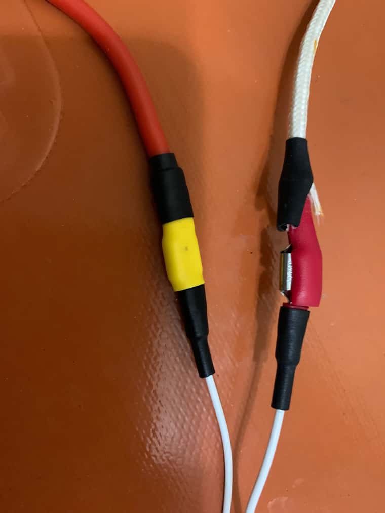
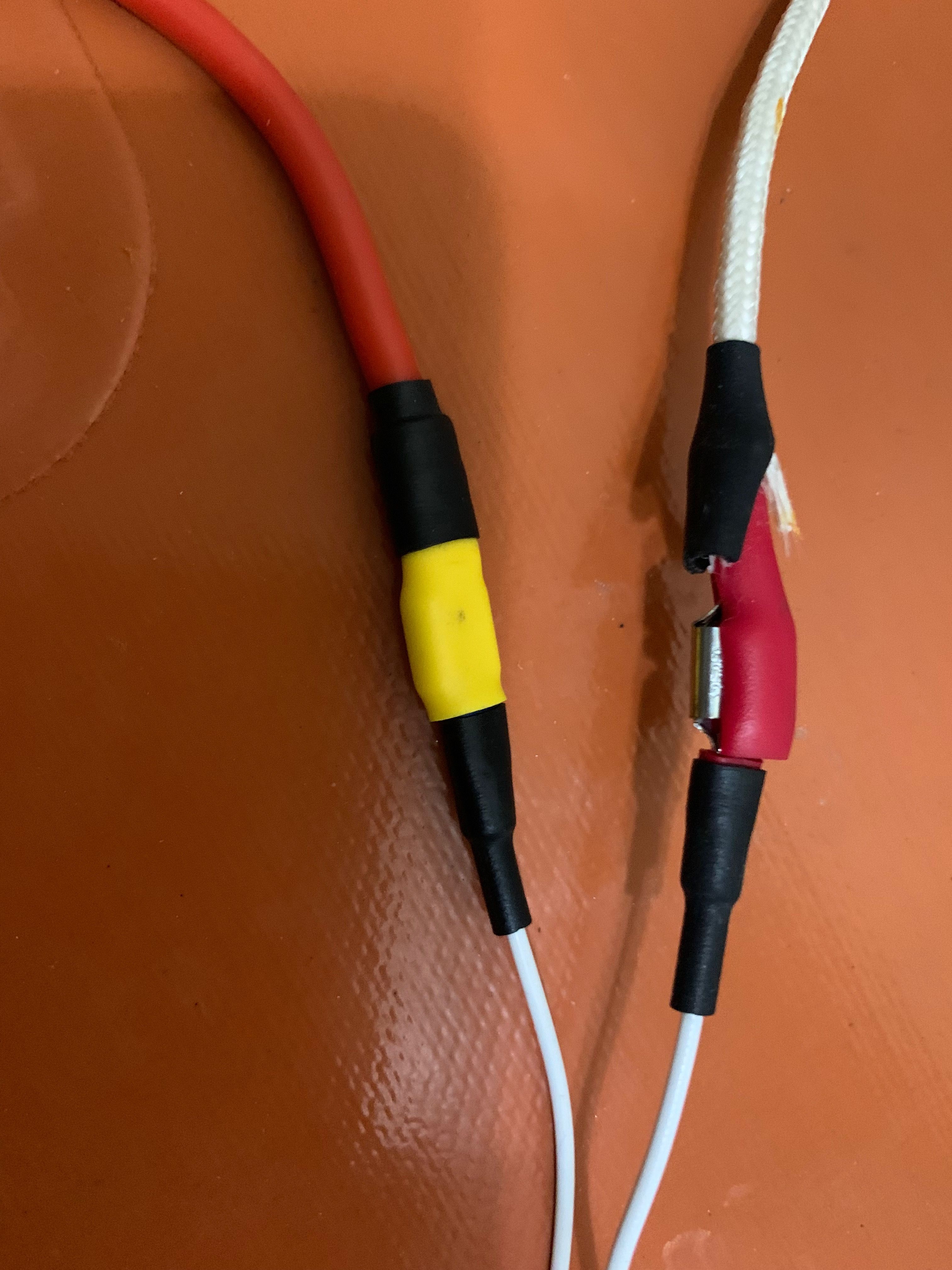
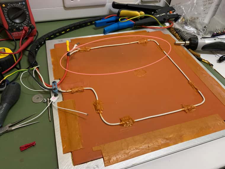
The sheathing/case of my crimp connector had been crushed slightly, splitting it open and although there's No scorch marks, it must have been shorting to the foil coated foam on my safety sheet (in-case heater mat adhesive gives up), all of which are Earthed.
If it wasn't for you guys helping me get my wiring done safely, this short could have been, well I don't think I need to say any-more.
Tested the heater (less the TCO), and I have 70.9Ω. So all good there.
Just need to rethink parts of my design now.
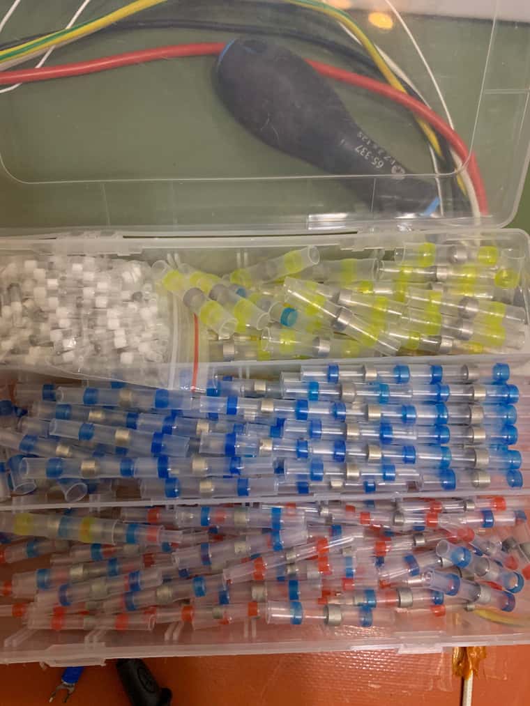
These heat shrink cable connectors/joiners, would these be safe to use on the heater/TCO cables?
I remember reading somewhere in the documents that it's generally best/safer practice to use physical connections on high current cables rather than solder, as the solder could soften.
Other than that, I may just have to increase the distance between the heater/tool-plate to the safety sheet to accommodate the crimp connections and maybe a layer of cork or something.Again, thank you for keeping me safe from having the correct Earthing and wiring in-place.
Oh yeah, I should state the blackened stuff around the perimeter of the heater mat is the Permatex Aviation Form-A-Gasket used to bond the heater mat to the tool-plate. It's not scotching or burns.
-
Glad this did not end worse.
It does leave a question though. A thermal fuse shouldn't smoke when it trips. So, where did the smoke come from? Seems your theory is the damaged insulation let the fuse short to the adjacent foil. But I recall from your re-wiring thread that you've set up a grounded chassis with ground-fault-interruption protection; so, why did your GFI protection not trip? Worth looking into.
Seems like replacement of the thermal fuse will restore functionality. I would not rely on typical heat shrink to wrap those connections; cheap heat shrink is polyolefin and does not have a service temperature high enough for reliable use on a bed heater, in my opinion. You can get high-temperature heat shrink with service to 250C or so. But in any case, I would probably use a fiberglass sleeve as the final layer over these connections.
As a final note, I prefer both my thermocouples/thermistors and bed thermal fuses to be touching the aluminum bed itself, not the heater. If the bed is being heated to 130C, the heater itself should get significantly hotter than this during heating phases, and that's fine. It's possible--repeat, possible, not guaranteed--that there was never any real control fault here, but that the fuse tripped when the heater got it too hot, even while the bed was in expected range.
-
@Dizzwold said in Dead Heater?:
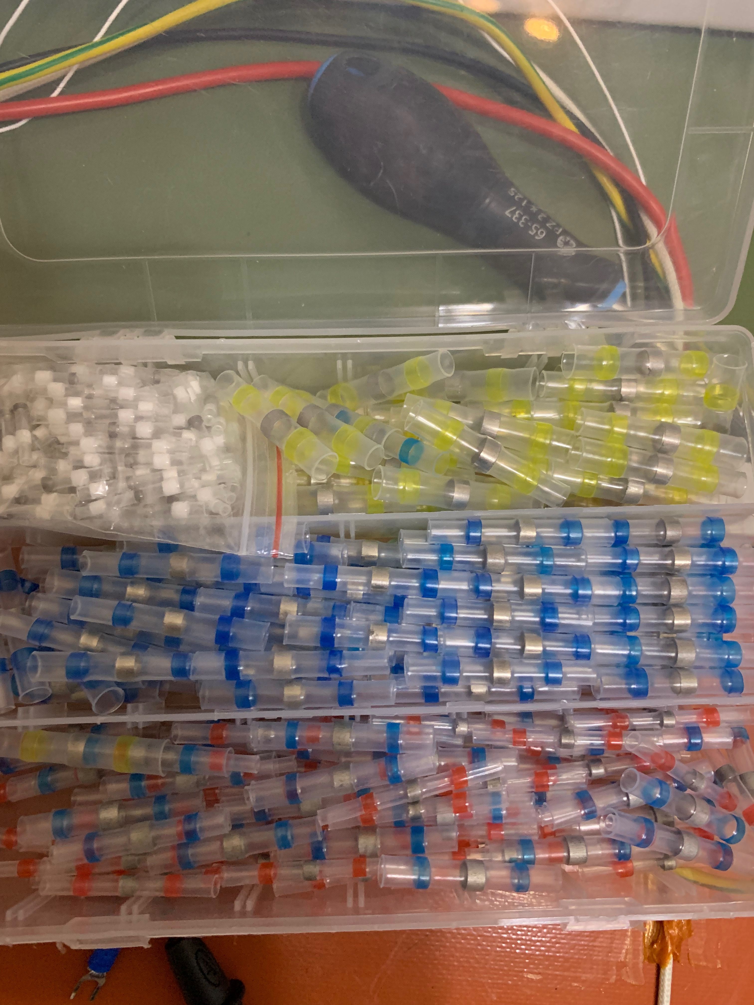
These heat shrink cable connectors/joiners, would these be safe to use on the heater/TCO cables?
If you mean solder sleeves, they use low melting point solder so not a good idea to use them in contact with a heater. You could use crimp-on heat shrink butt connectors.
-
@dc42
Sorry, I forgot to add the photo of them, but I think you are correct;
I assume your talking of these;

-
@Dizzwold yes and yes. For extra insulation (especially if the crimp tool has damaged the heatshrink insulation) you can put another layer of heatshrink over them.
-
I'm trying to recall my re-wiring and the ground fault interrupt.
Was it that I stated my Domestic Mains Fusebox has an RCD?
Which is correct, but yet this hasn't tripped...
I may invest in RCD protected wall outlet socket.
-
I have no expatiation as to why the RCD on my fusebox didn't trip, but I think I may have figured out where the smoke was coming from.
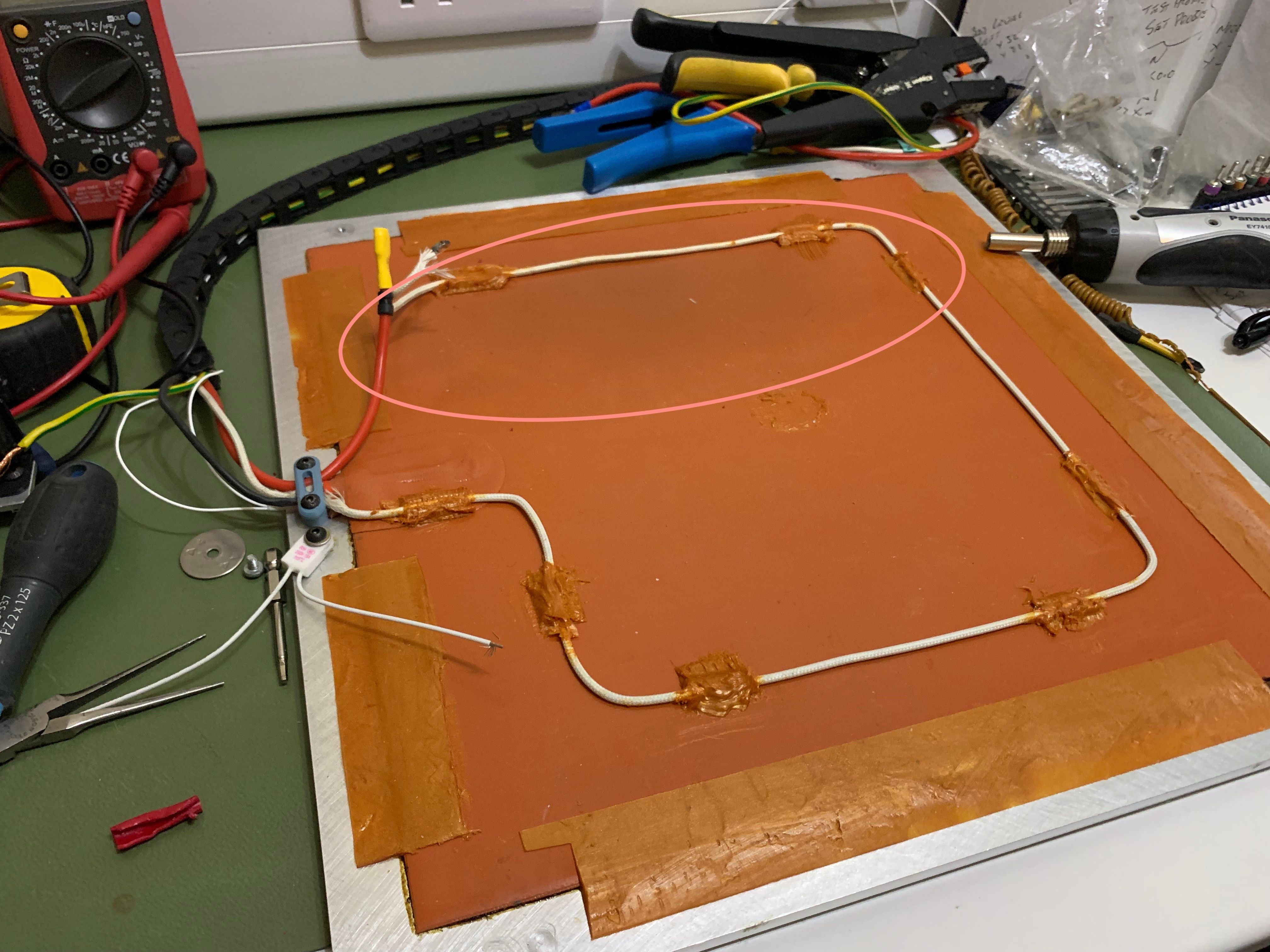
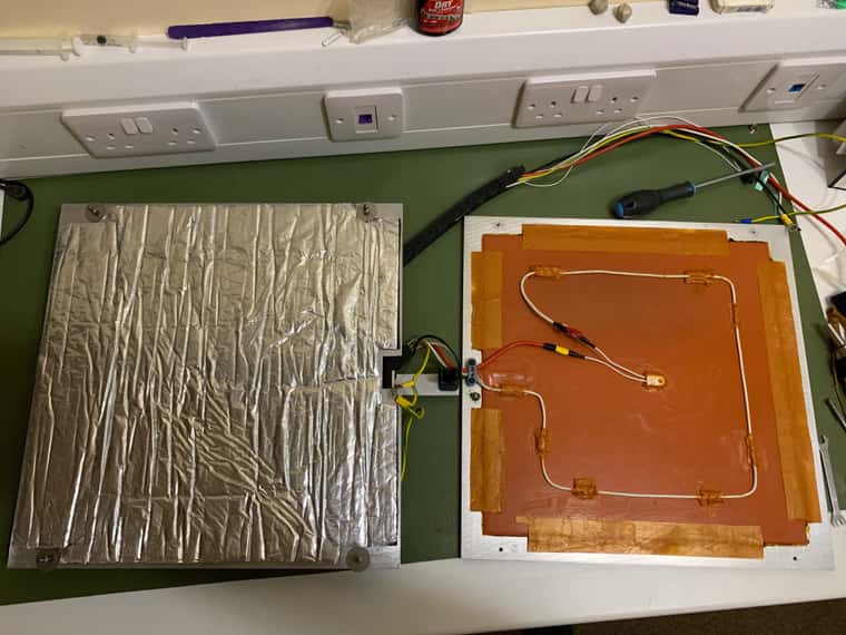
My build plate is assembled as follows;
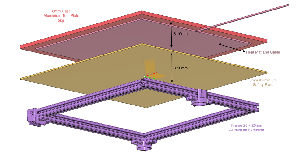
On top of the 2mm aluminium safety sheet is (sandwiched between underside of heater and safety sheet), is the bonded 3mm foam and foil sheet.
I've just realised everything but this foil sheet is earthed.
If I run a continuity test across the earthing to the foil sheet I get nothing, but if I press down on the foil sheet roughly where the damaged crimp was (heater cable), I get continuity.
So at this moment, and I'm only guessing, the smoke was from the foam burning and melting under the bonded foil and shorting the the safety sheet.
If I was to buy a DIN rail mount RCD which type should I choose A, AC, B, F, S ?
-
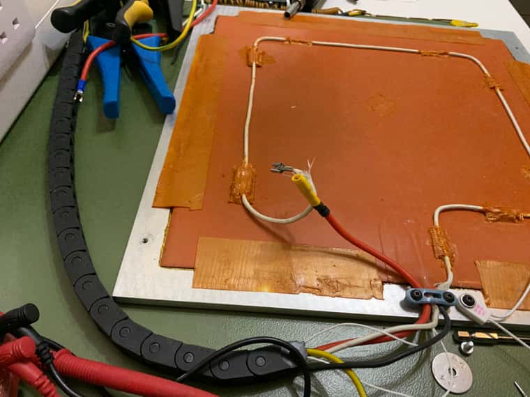
I think I'm going to have to re-bond the heater to the tool-plate, as I've found a few spots where it's delaminated (like air bubbles/pockets).
It's only a 4 or 5 spots, and the heater also has layer of High Temperature RTV around parts of the perimeter as an added protection against such, but being as I have the build plate Off and dismantled I may as well take the opportunity.
Is there anything that will remove 'my silicone' from around the perimeter and not damage the heater silicone?Just waiting on some longer bolts to attach the tool-plate to the assembly.
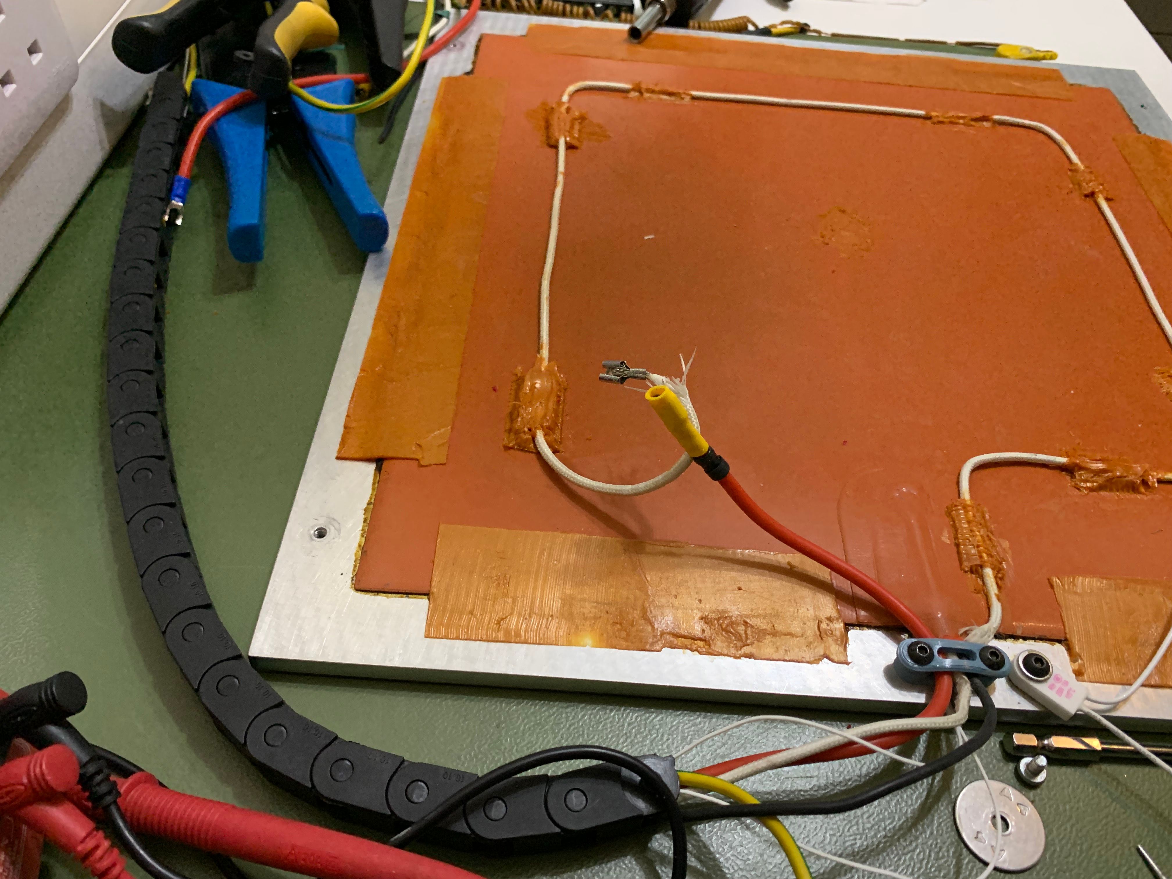
Something else I've noticed last night was a slightly darkened area around where I suspect the arcing happened.
I've tried cleaning this with IPA and microfibre cloth but it wont budge.
The heater still tests at 70.9Ω, so I'm hoping it's only smoke damage and not the heater (no scorching on the topside either).
I'll just have to test with caution.
-
There's no way to easily remove a bonded heater short of cutting. I've always considered it a one way operation.
-
@Dizzwold
@Phaedrux said in Dead Heater?:There's no way to easily remove a bonded heater short of cutting. I've always considered it a one way operation.
I second that; no easy way. Flat-razor scraper is probably your best bet, but it will be a pain.
I would not feel comfortable suggesting an RCD type to you. Central RCDs generally trip below 30 milliamps. At-wall GFCIs are about a fifth of that. So, should be way less ground current than would be necessary to create your smoking-bed scenario. The only thing I feel comfortable suggesting is having an electrician investigate whether your protection is working.
-
@Phaedrux. the heater isn't fully bonded with silicone. It's fully bonded with Permatex Aviation Form-A-Gasket, then High Temperature silicone around most the perimeter overlapping the heater.
My understanding is the Permatex Aviation Form-A-Gasket can be removed with IPA.The smoke which I thought originated from Arcing/melting of the foam/foil backing on the safety sheet persists.
I'd temporarily rewired everything and reassembled the printer, then found the smoke again, so I tried placing cameras with the build plate in-situ on the printer, but this didn't helped find where the smoke was coming from, other than the back right corner.
I wired everything up to bench with 2M cables running from the printer in it's enclosure across the floor and onto my work bench.
Guess what, No smoke???
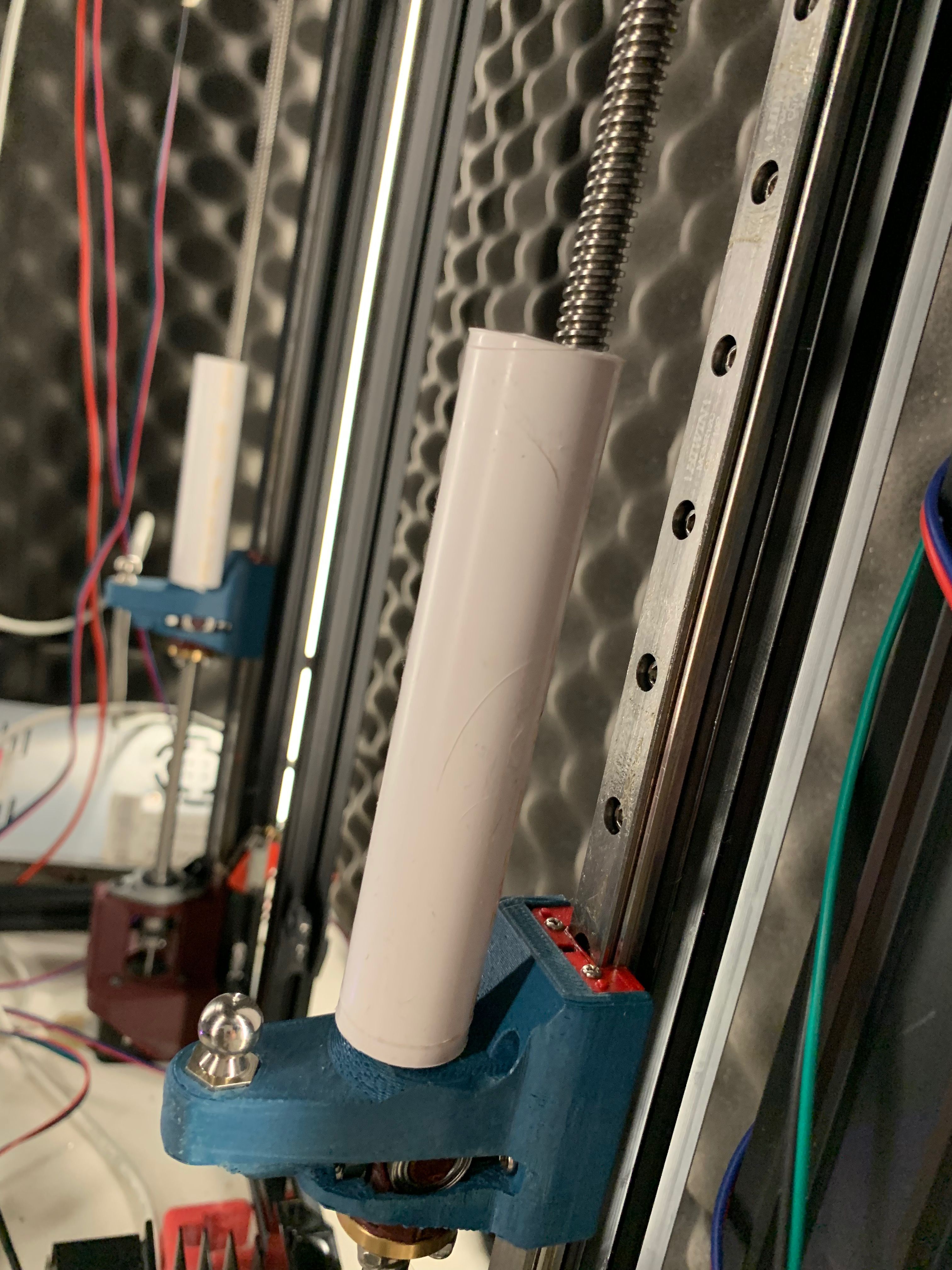
Heater worked.I'm wondering if it's, when I put the bed assembly on to the printer, I'm accidentally touching the lead screws and getting grease from the lead screws onto the edge of the bed. Then when I heat the bed it's burning off.
I'm going to have do more investigating, and I've now put some lengths or 20mm plumbing pipe over the lead screws.

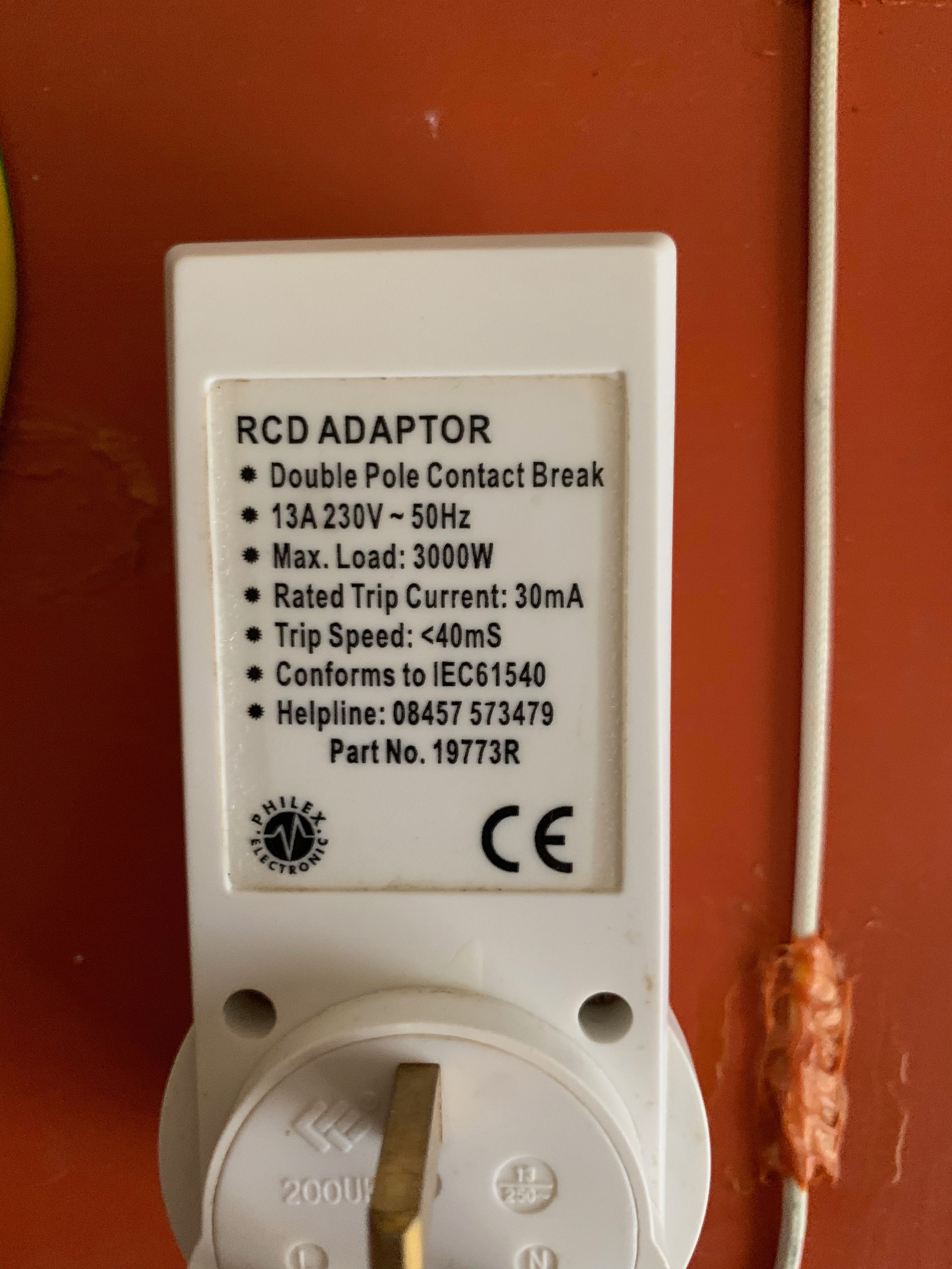
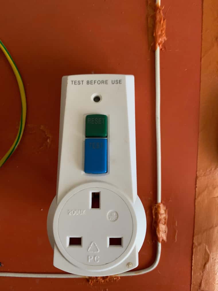
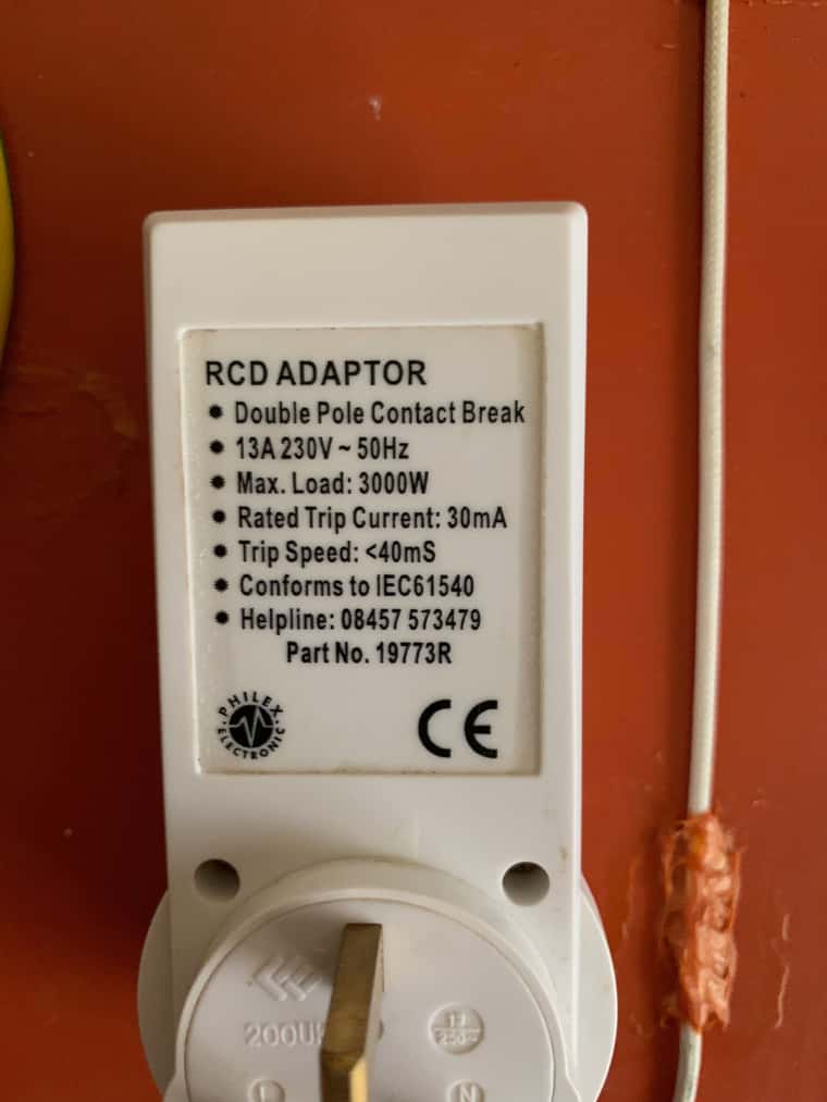
I've also since found this 'plug-in' RCD (buried in the garage). Weather this will be the correct type, at-least it should give some addition protection for the time being.
I've also ordered some DIN Rail terminals, and I'm going to build an individual wall mounted frame for all the electronics, and electrical, as it's just a tangled mess at the moment.