Duet 6XD RRF3 Create a Input and Check its Status
-
I have been trying to create an input on io6 using
M950 J1 C"io6 . in" in the config.g file
Then tried to check the status from the console with;
M950 J1
But always get - Pin io6 . in, active, true
I tried changing the state of the input by tying the pin to GND and 3.3V but the message never changes. Also tried to check the status of the input using
M409 K"inputs" but the output is not clear which input I should be looking at on the list.I also tried writing a simple macro
if sensors.gpIn[6].value != 0
M117 "Output should be on"
else
M117 "Output should be off"Not sure is the pin naming in the macro is correct so cannot trust the output of this macro.
In any case there is no change in message from the macro even though there was a change of input.Any help would be appreciated,
Thanks Mark
-
@machinemark you can use the object model browser plugin in DuetWebControl to observe the status of IO pins while you toggle them.
How do you have io6.in wired?
As a test you can connect it to ground with a simple switch.
-
I have tried switching the input to GND, then checking for a change of input from the duet side, then tried switching the input to 3.3 volt looking for a change of state and then out desperation tried switching the input to 5 volt still with no changes. Perhaps my naming or syntax in the macro is incorrect. ie the hardware side is no issue but not sure about the naming. When running M950 in config we declare the pin as J1 ie
M950 J1 C"io6 . in" in the config.g file (The spaces between io6 and the . and in are intentional cause I cannot send this message for the system sees it as a link and blocks it)
But then when we try to check the inputs status in the macro we cannot use J1 - it gives an error.
So triedif sensors.gpIn[6].value != 0
I have looked at the documentation and examples in the forums. I have tried variations but never see any sign of change on the software side. Also tried one of the opto isolated inputs;
M950 J1 C"!io5 . in . iso" -in config.g
But the same problems.
M950 J1 Gives the same message if the opto coupler is powered or not (24 volts at the input. The documentation states 10-50 volt so 24 volt should be safe and sufficient)
Also tried to see a change of state with the above lines in a macro adjusting the input number (or I think cause the naming is different)
Any help in using ie naming etc from a macro would be awesome because the frustration might cause me to see this control board as Frisbee that needs throwing!
Thanks Mark -
I have given you some upvotes so you can post links. That said if you post the code snippets as code then its easier to read and they wont be links.
e.g:
M950 J1 C"io6.in"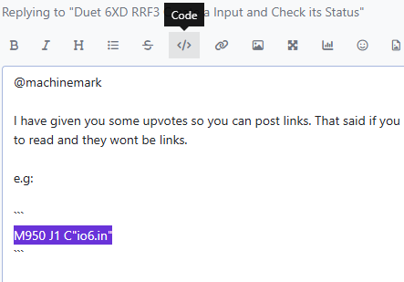
Using config command you used:
M950 J1 C"io6.inyou are creating IO input number 1 (J1)
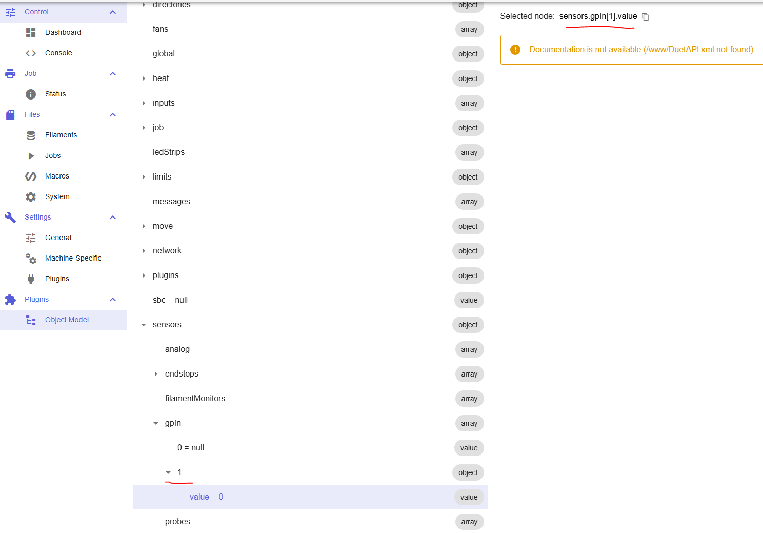
So the object model entry is:
sensors.gpIn[1]So a command like:
echo sensors.gpIn[1].valuewill work, note the array index of 1
The object model explorer will help a lot here:
-
@machinemark
note that M950 configures an input/output. Querying with M950 shows the configuration, not the state of that input/output. That’s why it doesn’t change.EDIT: apparently the above isn’t the case, and M950 does show the state of the pin. Make sure you’re grounding/applying 3.3V to the correct pin.
If you need the input to make something happen, eg run a macro, set up triggers on the input. See M581 and M582, and https://docs.duet3d.com/en/User_manual/Tuning/Triggers for examples.
EDIT: ignore this too, checking the OM is probably more straightforward.Ian
Bed-slinger - Mini5+ WiFi/1LC | RRP Fisher v1 - D2 WiFi | Polargraph - D2 WiFi | TronXY X5S - 6HC/Roto | CNC router - 6HC | Tractus3D T1250 - D2 Eth
-
@droftarts Thank you for the replies, I now have my head around the object model's Arrays, Objects and Value. I installed the plug in, studied it and was able to 'pluck' values using the echo command for eg;
echo boards[0].mcuTemp.current
boards is an array, element 0 holds mcuTemp with the value current
I seem to have run into another problem on using the 6XD I/Os. There are opto isolated inputs and outputs as well as the GPIO inputs and outputs.
Maybe I am not understanding but if I try to configure number 8 opto as well as number 8 GPIO out like the following in config ;
M950 S9 C"io8.out" 			; GPIO 8
M950 S8 C"!io8.out.iso"		; Isolated out 8
Then save, reset, and run
M98 P"config.g"Returns
Error: Pin 'io8.out.iso' is not free
Another bruise on my head, This the only use of io8.out.iso
Not sure how io8.out.iso is the same as io8.out ???The same happens with io8.in.iso and io8.in .
Is it a case of only being able to use one or the other??
On the positive,
I linked io8.out to io8.in with a jumper wire.
The following worked to setup a digital output and input.M950 P9 C"io8.out" M950 J2 C"io8.in"In config.g, save and reset
M42 P9 S0  ;Turn off the output
echo sensors.gpIn[2].value  ;Check the input
M42 P9 S1 ;Turn on the output echo sensors.gpIn[2].value ;Check the inputNot sure where to check the output status in the object model ??
Hope this helps someone who comes across this who is trying to turn on off an output / check an input etc before they plant their fist into the screen.
Thanks Mark
-
@machinemark said in Duet 6XD RRF3 Create a Input and Check its Status:
s it a case of only being able to use one or the other??
Yes. They are the same input, which is why they are both called io8. You have set up GpIn port 2 to use io8.in in your M950- command, so the status can be read from
sensors.gpIn[2].valuein the object model. The state of the output can be read fromstate.gpOut. -
Sorry, I am not following, 'have set up GpIn port 2' ?
I kind of get the object model and have had success 'plucking' / reading / echoing elements / values from the arrays.
Are the physical/hardware tied together internally so you can only use one in software - Surely not.
And this is what adds to the confusion.
I am looking at the documentation that shows the pin naming and it seems logical (at least to me) that io8.in is an input and io8.in.iso is another input.
So
M950 J2 C"io8.in"Maps io8.in to pin number J2
and
M950 J3 C"io8.in.iso"would map the isolated input to J3
But obviously not??
How, if possible do we make use of both the GPIO input and the ISOLATED input as independent entities ????
Thanks Mark
-
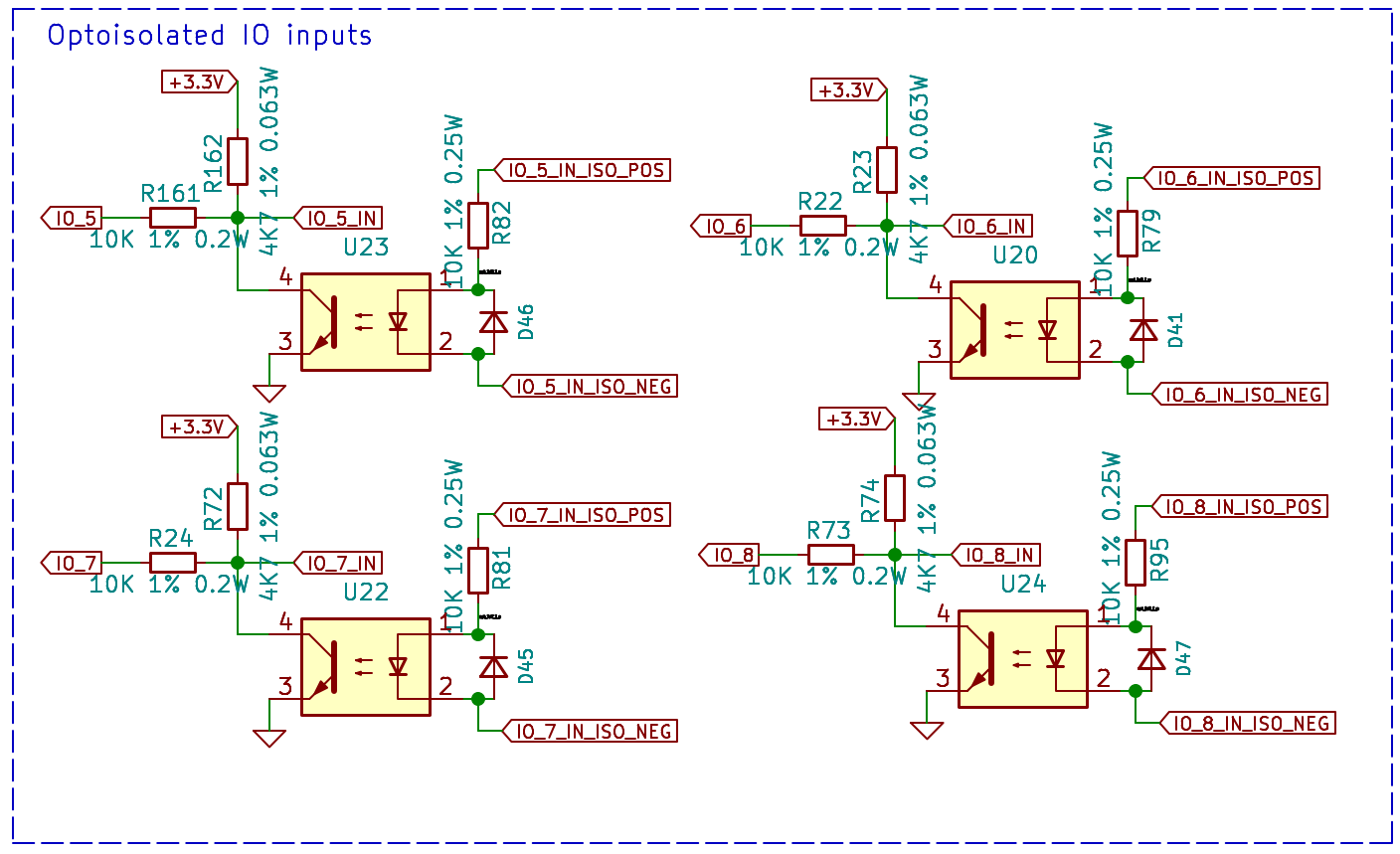
@machinemark you can see on the schematic that IO8,in and IO8.in.iso share the same MCU pin so can't be used at the same time
-
@machinemark said in Duet 6XD RRF3 Create a Input and Check its Status:
How, if possible do we make use of both the GPIO input and the ISOLATED input as independent entities ????
You can't. Yes, they are tied internally. It gives you the option of having an opto-isolated input, rather than a direct input. There are not enough spare pins on the MCU to have 4 extra pairs of I/O pins, so they are shared. As it says here https://docs.duet3d.com/Duet3D_hardware/Duet_3_family/Duet_3_Mainboard_6XD_Hardware_Overview#hardware-specification
Inputs/Outputs: 9 x on-board I/O connectors for endstop, filament monitor, Z probe, hobby servo, or PanelDue connection. Inputs are 30V-tolerant. 4 of the 9 pairs of IO also have alternative opto-isolated connectors.
Sorry, I am not following, 'have set up GpIn port 2' ?
You have set up 'GpIn port 2' with
M950 J2(J for 'general purpose Input', 2 for the port number that you can use to reference it) on pinC"io8.in".Ian
-
Thanks for clarifying and providing the schematic showing the two inputs tied internally.
Thanks Mark