Sovol SV08 Multiple Motion System Upgrade.
-
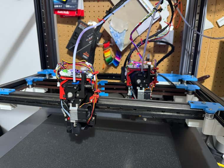
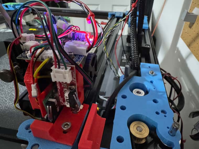
@dwuk One thing I noticed in an earlier picture was some scratching belts:
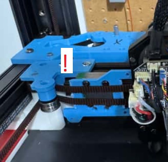
I thought it was just temporary, but it still seems a problem.
-
@o_lampe Well spotted - yes it is due to the extra IDEX carriage I left on the rear gantry.
If I take off the plastic coupler from the carriage there is a risk of the carriage falling off the end of the rail and I think it is that which is clashing with the belts.For the IDEX phase I am going to need to move the pulley positions slightly forward to avoid the problem you spotted - but in the meantime I don't think it is causing any great issues other than limiting travel - but will find out when I do some more testing.
I am starting to think about Reprap IDEX kinematics -
I was pleasantly surprised to find that CoreXYUV seems to support two CoreXY gantries ok - but for IDEX on top of CoreXYUV I think I am going to have to work out how you define completely new Kinematics (if thats possible) otherwise it is going to end up with loads more fairly complicated post-processing.
I think what I would really need is to be able to have an X and 'x' axis for each gantry that I can specify both coordinates for in G0-G3 commands (or Macro replacements) I.e. For mirror mode / duplicate mode etc.- Rather than using a command to change the mode between Toolchange/Duplicate and Mirror - it should be fairly easy to work out and send two X coordinates in the same G0-G3 command to achieve the desired effect.
So what I will be looking for is something like CoreXxYUuV for dual gantry IDEX.
With .Zabcd - for the Z hoppers, and then finally. CoreXxYUuVy - for the occasionally moving bed phase (5).My current thinking on IDEX too is that I will stick with the Ratrig VCore4 approach of two extra Y motors per gantry initially (although it would be nice to reduce this down to one extra per ganty) - but I think I will try putting them at the front rather than the back to help balance the weight on my flying gantries.
-
@dc42 Have spent a fair bit of time trying to get this sensorless homing on the tool board Mini5+ to work - I reduced V right down to 100 - but I still can't get it to accept a speed - it just keeps saying too slow or too fast - so will give up on this for now - and go back to adding switches.
I think I will add some switches directly on the extruder for the U/X Axis - to take advantage of the inputs available on the 1LC boards.
Have applied the Io1.in Z probe change to both extruders now and tidyed up the wiring on the two extruders a fair bit.
I think I need to get U & V end stops working properly - then 4 Z bed levelling working properly before I attempt my first print - as at present the rear axis seems to droop a bit - probably due to the 4 motors on it at the back.
-
@dwuk said in Sovol SV08 Multiple Motion System Upgrade.:
I think I will try putting them at the front
"Goodby toolchanger" then? Isn't there a way to distribute the steppers to the left and right, keeping the front available for extra tools? Steppers aren't exactly lightweight and you'll need some beefy motors to overcome the friction of the idler pulley-orgy.
I mentioned it before, but my hashPrinter only needed 4 motors for 4 semi-independent toolheads. The super simple gantry was the reason why I built it.
-
@o_lampe Yes would be good if I could get down to 4 motors for 4 heads.
May well explore other multi head options at some point - I guess the disadvantage of a hash printer is not easily being able to move heads not in use out of the way.
I think it will be easier though in terms of belt paths to keep with the double Y axis approach - with belts just going between the front and back.
Trying to keep to one extra motor per gantry would I think need the belts to run around both sides and either across the back or across the gantry.
I'm not thinking of putting motors side by side at the front - just on top or below - so I don't think it will affect tool changing.
On look at it a bit more closely I think on the bottom isn't going to work - so will just put one motor on the front top on each gantry - with the other two at the back.
-
End stops now working on U & V axis - so the next thing I need to work out is how to home Z - I have 2 x Z probes and depending on how the Flying Gantry has settled either one or the other triggers first.
Ideally I would like a way of Z homing where it tries to home - and stops if either of the probes are triggered, perhaps with one gantry right at the front and the other at the back.
I tried specifying both as switches in a M574 - but it didn't like it.
Then I guess what I would like to do is then joggle around the front and rear Z axis motors until both probes trigger very close to each other.
I can't work out how to do this at the moment, so in the meantime I think I will Z home on the rear probe, but move it is close to the front probe first - so that the front gantry doesn't hit the bed if it is lower.
Will then try 4 Z motor adjustment.
Probably also need to put in some basic method of avoid the heads or gantries being able to move in to each other in normal ad hoc moves if that's possible.
U & V end stops both put in the 1LC driver board - which saves on wiring - but does mean U has to be homed first - otherwise the V end stop won't hit the plate I setup for it.
-
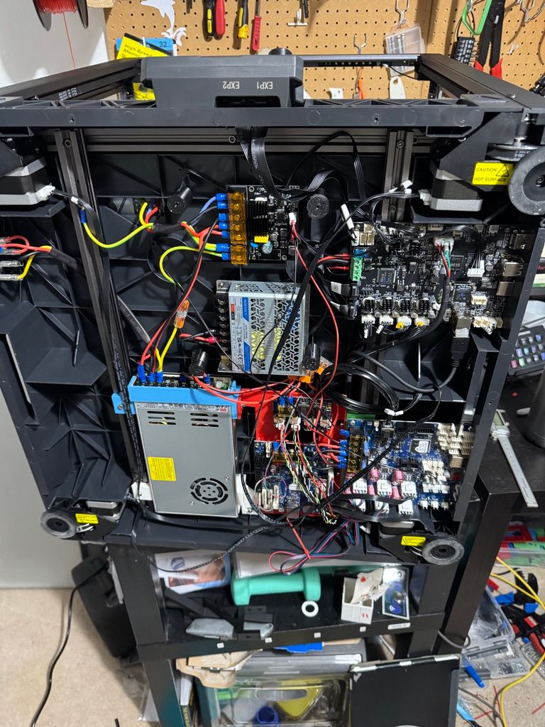
@dwuk Upgrade PSU to a meanwell one - I can see why people seem to like them - its almost silent, rather than being really noisy like the previous one.
I think I might be getting somewhere with my homing
Based on here
https://docs.duet3d.com/User_manual/Connecting_hardware/Z_probe_auto_levelling#axis-levelling-using-endstopsI think I might have to split my 4xZ motors in to 2 separate AXIS (back and front), then move the two gantries to the back and front, then allocate the two probes to the two separated Z Axis, and then move down on both axis down at the same time - and hopefully it will move down until both probes are triggered.
-
Think I have figured a way to get the Z motors level.
Step 1 - Define an extra AXIS A in Config.g with same parameters as Z - but set to a dummy drive and switch.
Step 2 - Align Back and Forward.
Move front gantry to near front centre and rear gantry to near rear centre
;Set Z axis to Probe 0 - front gantry
M574 Z1 S2 K0
;Set A axis to Probe 1 - rear gantry
M574 A1 S2 K1
;Split Gantries - front and back
M584 Z2:5 A0:1 P6
;Move both gantries down until they hit their probes
G91
G1 H1 Z-999 A-999Step 3 - Align Left and Right
; Now Move Gantries close to each other in the centre of the bed,
; Plus move rear gantry print head to near to the left and front to near to the right; Resplit Axis - with A left and Z right
M584 Z1:5 A0:2 P6; Now Move down to end stops again
G91
G1 H1 Z-999 A-999; Now all 4 z's are I think closer to alignment.
Step 4 - Re Merge Z
M584 Z1:2:0:5 P5 -
Homing working -
See short video demo
https://youtube.com/shorts/oHtVsdHTPQc?si=w-lnOgmzNzxqfvRK
Lots of refinements to do - but basic homing and 4 AXIS levelling done
-
Tuned heaters today. The heads worked ok, got this from the print bed
28/01/2025, 11:29:21 Warning: heater behaviour was not consistent during tuning
Auto tuning heater 0 completed after 3 idle and 25 tuning cycles in 4667 seconds. This heater needs the following M307 command:
M307 H0 R0.527 K0.163:0.000 D5.70 E1.35 S1.00 B0
Edit the M307 H0 command in config.g to match this. Omit the V parameter if the heater is not powered from VIN.Will try using it anyway to see what happens.
Also decided to try backing up settings today - tried various methods and ended up using FTP with VSCODE. Annoyingly I some how ended up losing my HomeX,Y,Z and All settings - so had to re do them.
Improved the Z homing as part of this.Now ready to try some mesh levelling.
-
Gradually getting there with bed levelling.
Found my two probes trigger at slightly different heights, plus the nozzles are also at different heights too - so will add some manual adjustment capability in before trying first print.I can't get auto 4 axis calibration to work - it keeps saying it is not supported for the kinematics. I've tried coreXY too and it still says the same thing.
So I have settled for now on probing and a level of auto adjustment in bed.g that seems to work.
My HomeZ does still seem to mess up the gantry levelling, and I am getting some issues with probes getting stuck on in the software.
But I think with this bed.g I now have a pretty flat Z axis after a few iterations.
M671 X410:-60:-60:410 Y420:-10:420,-10
M400

while true
    G1 X300 Y200 F20000
    G30 P0 X300 Y200 Z-99999 ; probe near a leadscrew

    var adjust1 = (sensors.probes[0].lastStopHeight)


    G1 X20 Y20 F20000

    G30 P1 X20 Y20 Z-99999 ; probe near a leadscrew

    var adjust2 = (sensors.probes[0].lastStopHeight)


    G1 X20 Y200 F20000
    G30 P2 X20 Y200 Z-99999 ; probe near a leadscrew

    var adjust0 = (sensors.probes[0].lastStopHeight)


    G1 X300 Y20 F20000
    G30 P3 X300 Y20 Z-99999 S-1 ; probe near a leadscrew and calibrate 4 motors


    var adjust5 = (sensors.probes[0].lastStopHeight)

    echo var.adjust1, var.adjust2, var.adjust0, var.adjust5

    if (abs(var.adjust1) < 0.01 && abs(var.adjust2) < 0.01 && abs(var.adjust0) < 0.01 && abs(var.adjust5) < 0.01)   || iterations > 6
        break


    G91

    if abs(var.adjust1) < 1
        set var.adjust1 = var.adjust1 * 2
    if abs(var.adjust2) < 1
        set var.adjust2 = var.adjust2 * 2
    if abs(var.adjust1) < 1
        set var.adjust0 = var.adjust0 * 2
    if abs(var.adjust1) < 1
        set var.adjust5 = var.adjust5 * 2


    M584 A1 P6
    G1 A{var.adjust1}
    M584 A2 P6
    G1 A{var.adjust2}
    M584 A0 P6
    G1 A{var.adjust0}
    M584 A5 P6
    G1 A{var.adjust5}


M400
G1 Z0 F2000
G92 Z2.55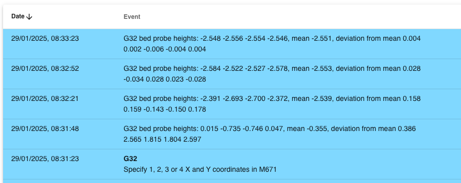
-
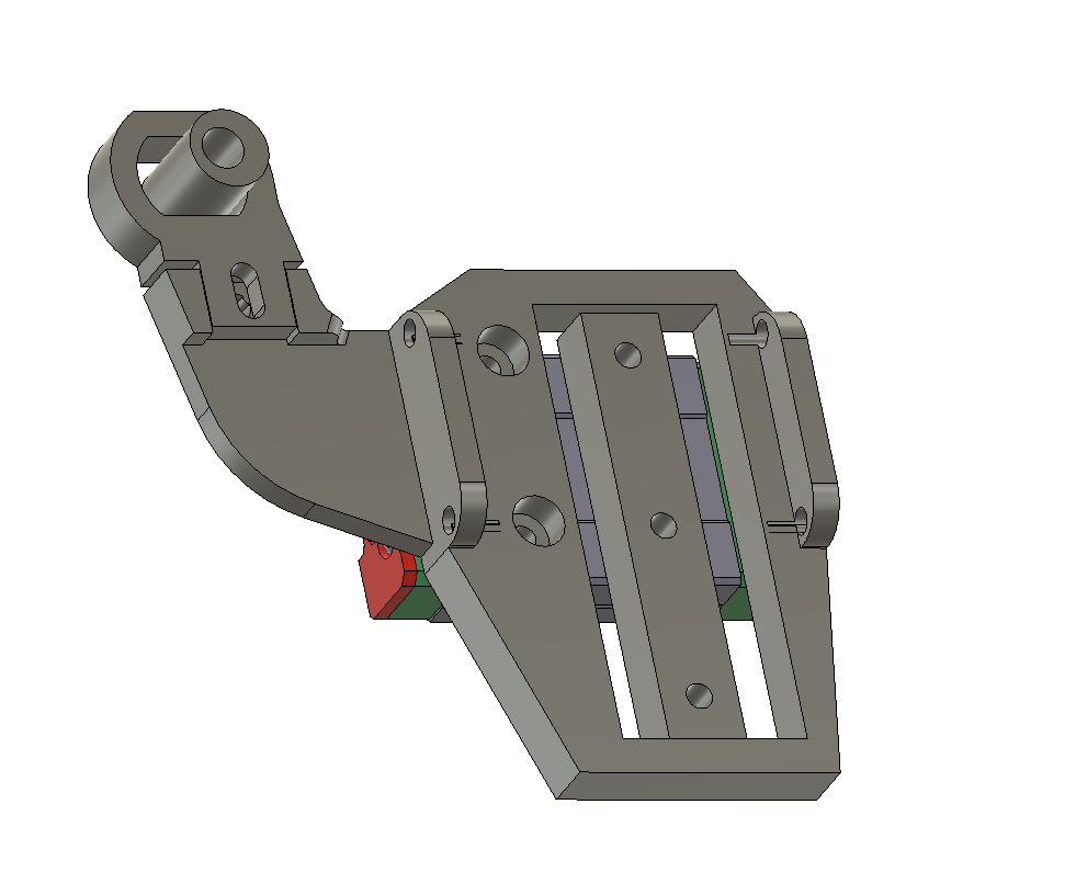
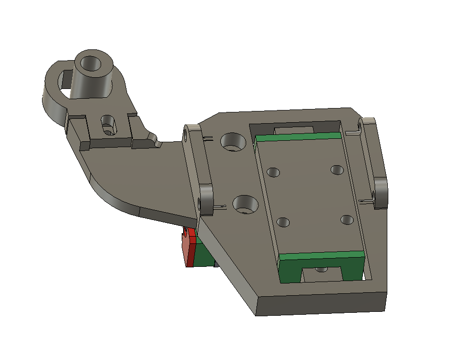
Current thinking on first Z Hopper prototype
an MG90S servo - for Z offset, first layer meshing and Z hopping only for other layers.
The mechanism will unfortunately add another around 10mm to the depth of the extruder due to the tiny MGN7 linear rail.
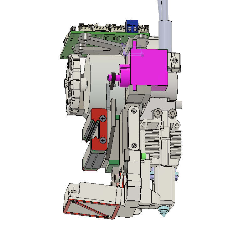
I don't think the 1LC board 5V can handle the stall current of about 700ma - so will add a buck convertor onto the 24v input supply. Will put the servo on IO-0.out on the 1LC.
-
@dwuk Hi David,
I did a quick sketch to show you the cam concept. I can't upload a photo, so I put the link below. You should erase the spaces.
I tried to use arrows to explain which part is which.
You should add a mechanical switch to limit the lower Z position of the extruder. When the extruder reaches the lower Z limit, the spring should have slight tension—this will likely provide sufficient accuracy.
Additionally, if you add a screw to adjust the lower Z limit, you can fine-tune the adjustment to ensure both extruders are on the same plane.
https :// freeimage . host / i/2Qk9jcl
-
@_MRT_ Thanks very clever- like it.
Especially the fact that is should allow more precision and also the servo motor will not need to take the full weight in its rotational axis. Will add limit switch in too as you suggest.
Have added a screenshot of your photo below.
-
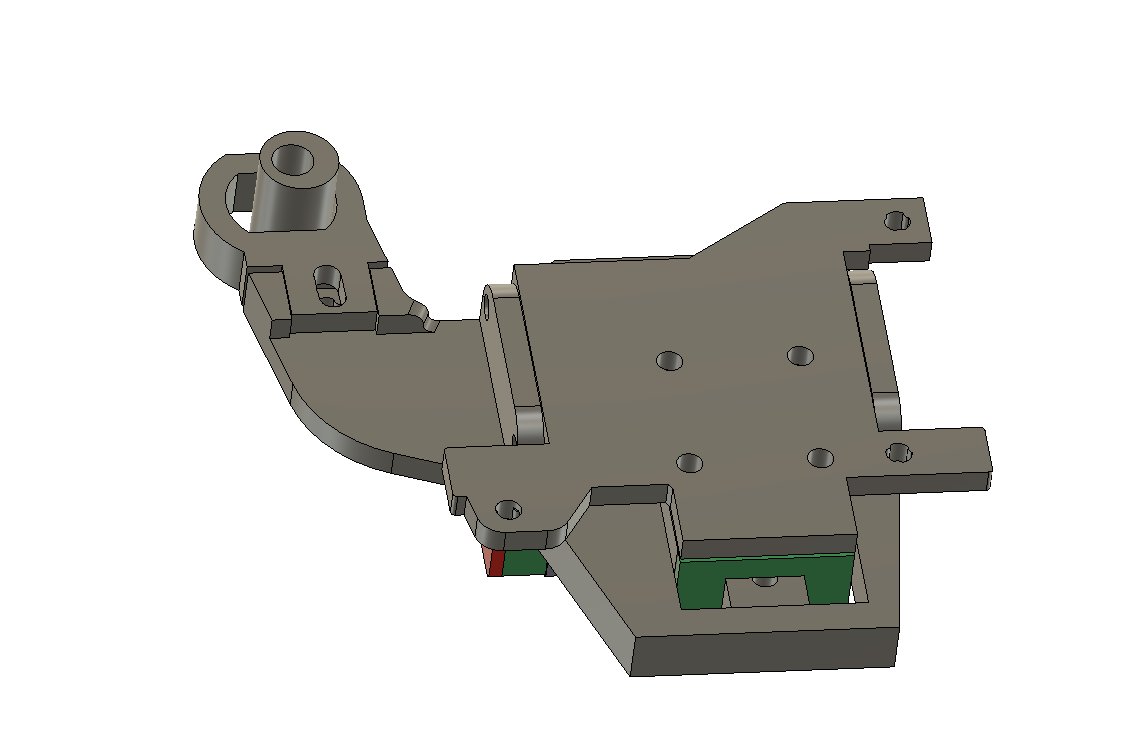
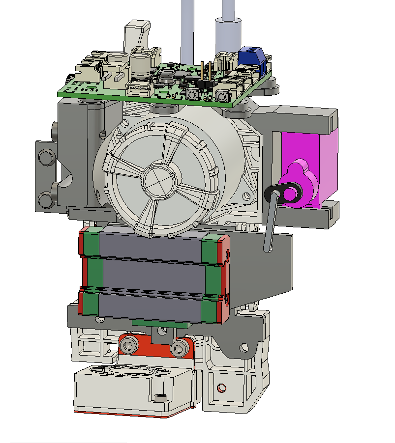
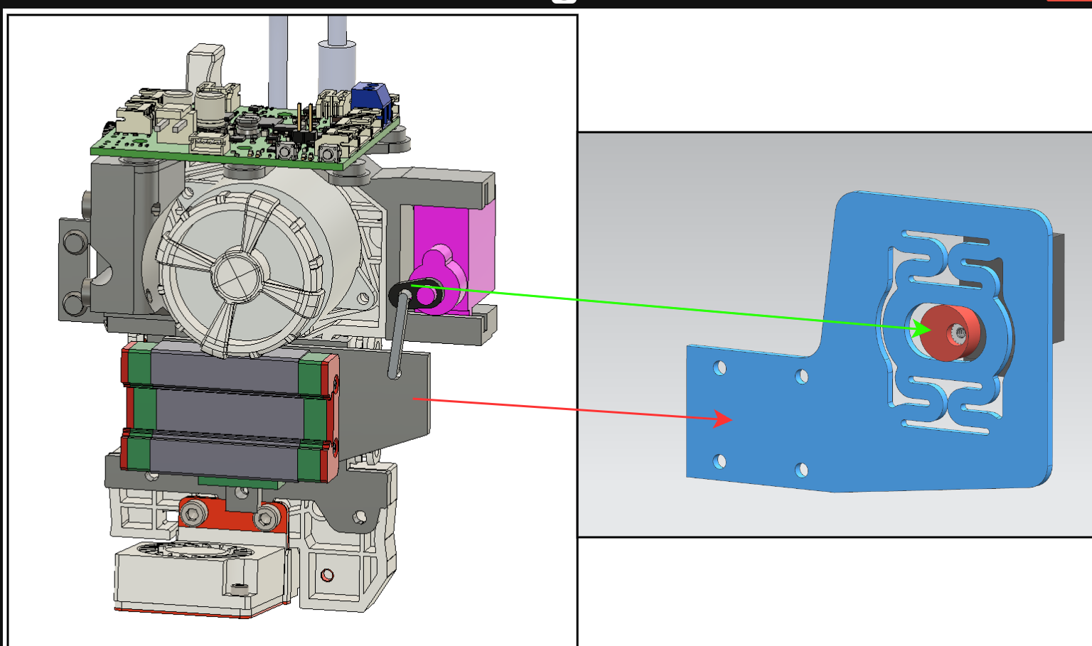
@dwuk Basic rigid Cam version created for first test.
Will then experiment with adding springs as suggested by @_MRT_
Need however to limit the width as much as possible to avoid clashes with the other head on the same gantry. I guess I could move the servo and cam onto the other side and reposition the X end stop.
The Cam is offset 0.75mm from the centre of the shaft - so I am guessing this means about 1.4mm of movement within the range of about 140 degrees of the servo.
Will add in screw height adjustment and end stop later.
-
@dwuk Servo wired up and tested. On the 1LC board io_0.out, with an LM2596 DC to DC convertor to bring down the 24V input to 5V for the servo.
Prototype parts printed - just need to install them and test them - might be a few days due to other commitments.
-
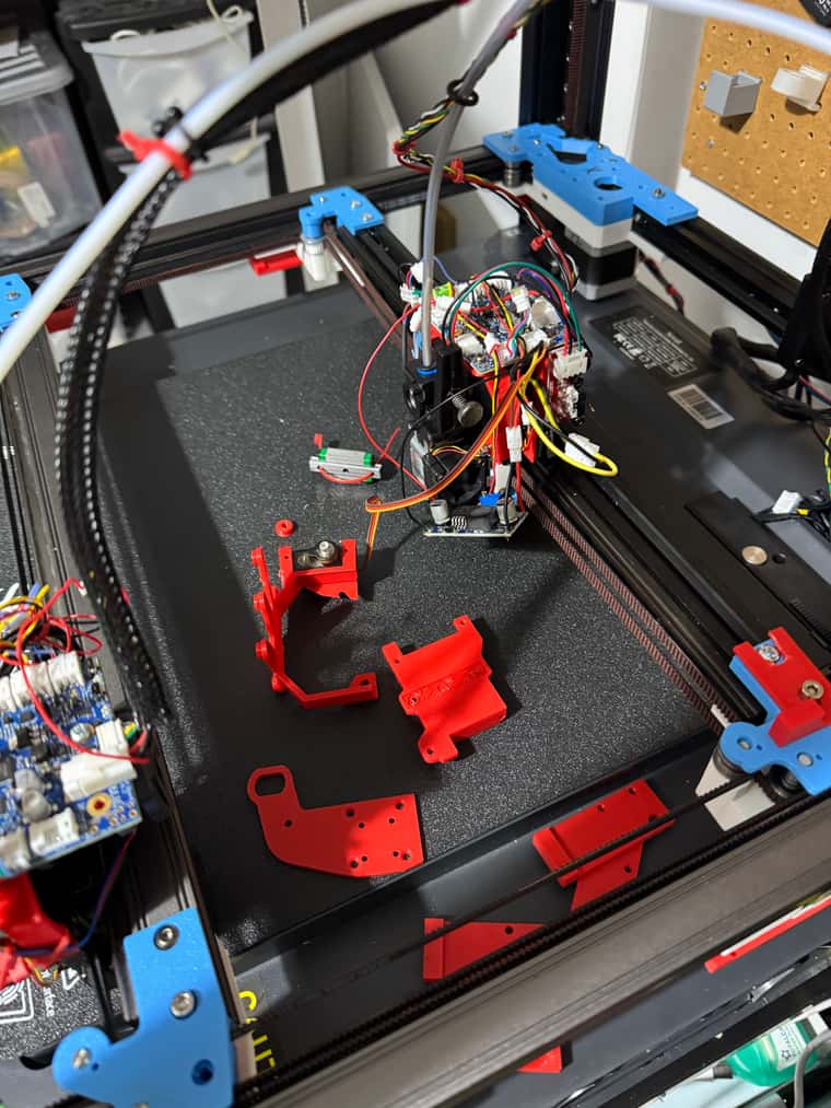
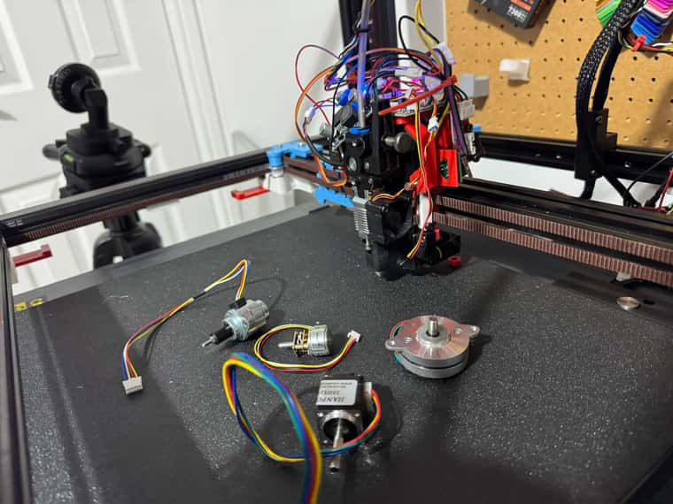
Back from holiday - lots of deliveries while I was away - so ready for IDEX.
Made mistake with Order I think and bought 30 Buck Convertors instead of the 3 more I need - but only about £12 for all of them. All got a nice variety of end stops - both optical and mechanical.
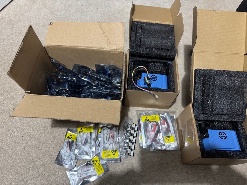
Also now have various different stepper motors to try for z hopping in addition to servo. Think a stepper motor might be easier to control as will be able to set it as an AXIS which will move in line with head moves when doing bed mesh adjustments. I think the tiny geared stepper motor in the middle from ThePiHut with a cam is probably the best solution. But the larger linear stepper also a possibility.
First test of servo lifter - need to make some changes - probably to move belts to be on fixed part rather than moving part. Also should probably move servo back a bit plus add a bearing to the cam,.
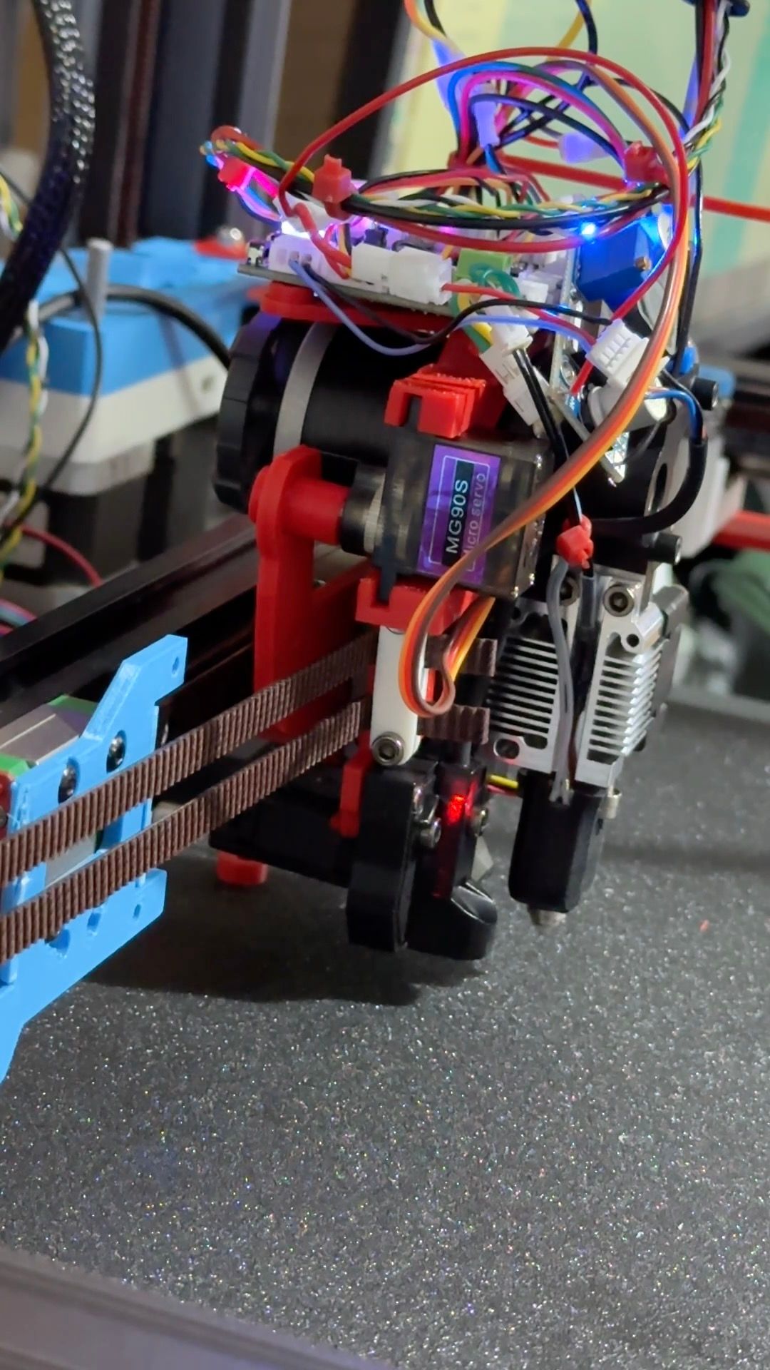
But anyway it works - see short video.
https://youtube.com/shorts/AQexkpbFp64?si=ysh9GKfc63iHuNRg -
@dwuk said in Sovol SV08 Multiple Motion System Upgrade.:
add a bearing to the cam
That's what I meant before when I said use excenter bearings. Three of them in a planetary gear fashion could also replace the mgn-linear guide and have a wider footprint.
I'm not good with CAD or napkin drawings, otherwise I'd sketch up an example. Probably best suited for a pancake stepper. -
@o_lampe Thanks - I thought It was probably getting closer to what you were suggesting - but I am afraid I still don't really understand the planetary gear suggestion, especially how it would eliminate any side to side movement - but it sounds interesting if it can eliminate the need for the linear rail and if possible remove some depth from the solution.
I am thinking I am going to need some sort of gearing to have enough power to lift the print head.
-
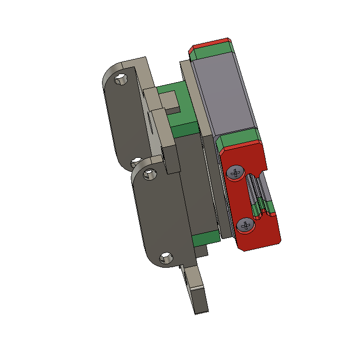
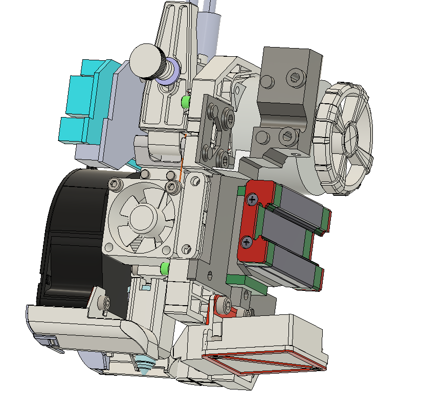
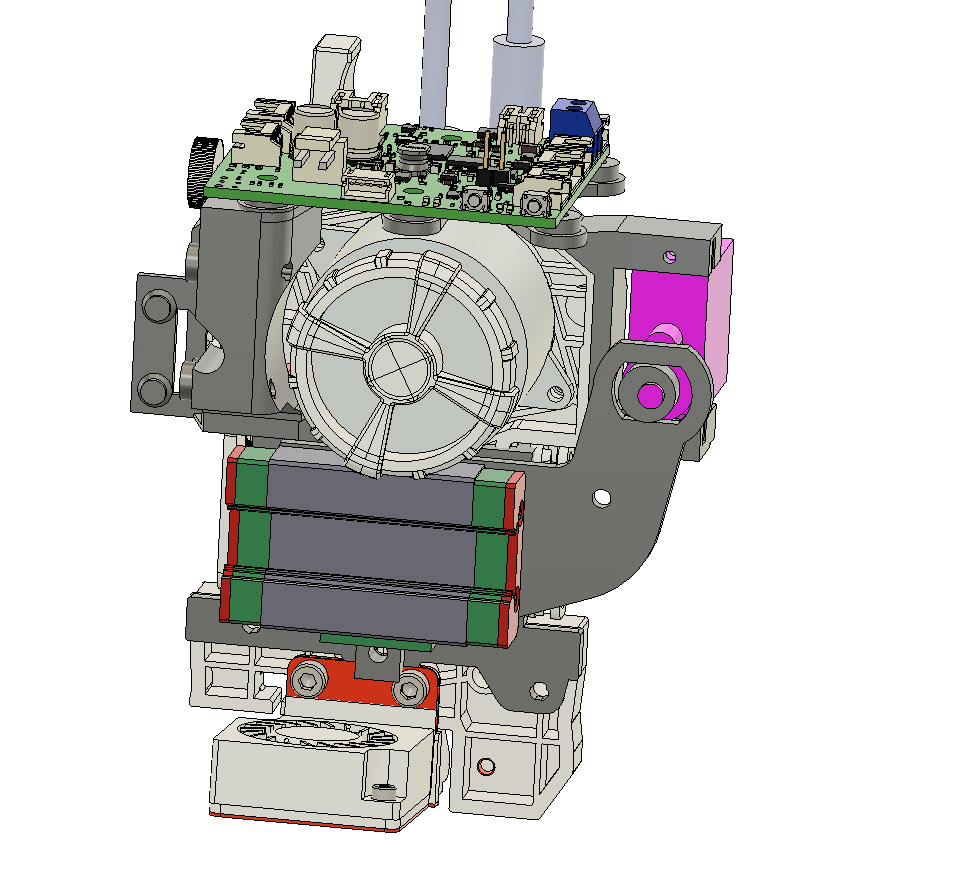
Not getting consistent Z heights with the new 'z-hopper' extruder, so remodelled it with a bigger linear rail (MGN9 vs MGN7), plus also made the rail bolt directly onto the back of the main X carriage - this will hopefully eliminate a lot of the wobbles.
Also corrected the issue with the belts being on the moving side, rather than the fixed side.
Also improved G32 / bed.g macro a bit - but would really like to get G30 S4 working properly - rather than having to the do calculations myself.